Montage- und Betriebsanleitung Mounting and operating instruction Montage et mode d emploi
←
→
Transkription von Seiteninhalten
Wenn Ihr Browser die Seite nicht korrekt rendert, bitte, lesen Sie den Inhalt der Seite unten
Montage- und Betriebsanleitung
  Mounting and operating instruction
     Montage et mode d´emploi

                      KEMA 01ATEX1053 X
                       Bitte zur künftigen Verwendung aufbewahren
                               Please retain for future usage
                           Veuillez conserver pour un usage futur

          Schwimmer – Magnetschalter
             Magnetic float switches
  Régulateurs de Niveau à Flotteur Séries 60 et 80

014487 _Rev.05_22.01.2020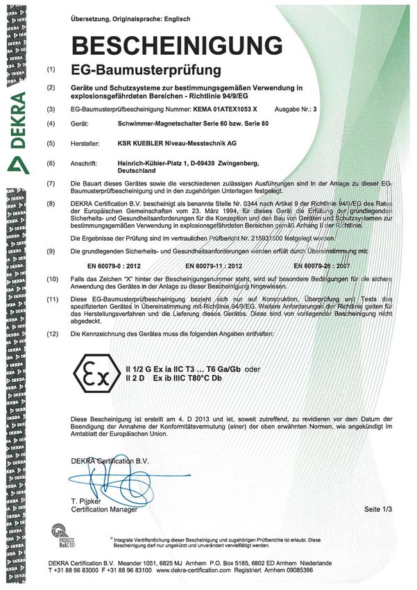
EG-Baumusterprüfbescheinigung
EC-Type Examination Certificate
Attestation d’Examen CE de Type

EG-Baumusterprüfbescheinigung
EC-Type Examination Certificate
Attestation d’Examen CE de Type
EG-Baumusterprüfbescheinigung
EC-Type Examination Certificate
Attestation d’Examen CE de Type
EG-Baumusterprüfbescheinigung
EC-Type Examination Certificate
Attestation d’Examen CE de Type
EG-Baumusterprüfbescheinigung
EC-Type Examination Certificate
Attestation d’Examen CE de Type
EG-Baumusterprüfbescheinigung
EC-Type Examination Certificate
Attestation d’Examen CE de Type
EG-Baumusterprüfbescheinigung
EC-Type Examination Certificate
Attestation d’Examen CE de Type
EG-Baumusterprüfbescheinigung
EC-Type Examination Certificate
Attestation d’Examen CE de Type
EG-Baumusterprüfbescheinigung
EC-Type Examination Certificate
Attestation d’Examen CE de Type
a
I(sRXITAEELER A drvison ol the W(A Group
\=ä
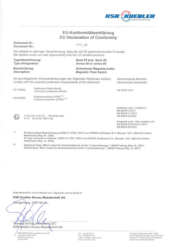
E U-Konfo rm itätserkläru n g
EU Declaration of Conformity
Dokument Nr.:
1111 _02
Document No.:
Wir erklären in alleiniger Verantwortung, dass die mit CE gekennzeichneten Produkte
We declare under our sole responsibility that the CE marked products
Typenbezeichn ung: Serie 60 bzw. Serie 80
Type Designation: Series 60 or series 80
Beschreibung: Schwimmer Magnetschalter
Description: Magnetic Float Switch
die grundlegenden Schutzanforderungen der folgenden Richtlinien erfüllen: Harmonisierte Normen:
comply with the essenfia/ protection requirements of the directives: Harmonized standards:
Gefährliche Stoffe (RoHS)
20111651EU EN 50581:2012
H azardo u s subsfances (RoH S)
Explosionssch utz (ATEX)(1)(2)
2014t34t8U
Ex p I o si o n p rote ctio n (ATeYyr t't
t
Zerlifiziet nach I Certified to
EN 60079-0:2012
EN 60079-1 1 :20'12
ll 112 G Ex ia llC T3 . . . T6 GalGb oder EN 60079-26:2007
ll 2 D Ex ib lllC TBO'C Db
Entspricht auch I Also complies with
EN 60079-0:2012+41 1 .2013
EN 60079-26:2015
EG-Baumusterprüfbescheinigung KEMA01 ATEX 1053Xvon DEKRA Certification B.V. Meander 1051,6825 MJArnhem,
Niederlande (Reg.-Nr. 0344).
EC type examination certificate KEMA 01 ATEX 1 053 X von DEKRA Certification B.V. Meander 1051 , 6825 MJ Arnhem,
Netherlands (Reg. no. 0344).
Notifizierte Stelle: IBExU lnstitut für Sicherheitstechnik GmbH, Fuchsmühlenweg 7, 09599 Freiberg (Reg.-Nr. 0637).
Notified Body: IBExU lnstitut für Sicherheitstechnik GmbH, Fuchsmühlenweg 7, 09599 Freiberg (Reg. no. 0637).
Unterzeichnet für und im Namen von I Signed for and on behalf of
KSR Kuebler Niveau-Messtechnik AG
rg,2 -06-
CEO
ebler Niveau-Mess iK AG
KSR KUEBLER Nlveau-lMesstechnlk AG Tel.: +49 6263 B7-0 Amtsgericht Mannheim HRB 714806
Heinrich-Kuebler-Platz 1 Fax: +49 6263 87-99 Vorsltz des Aufsichtsrates: Dirk Fellermann
69439 Zwingenberg E-Mall: info@ksr-kuebler.com Vorstand: Thomas Ger ing (Vorsitzender)
Deutschland www ksr krreb er aom Gerichtsstand: Ir4osbach/BadenDeutsch .............................................................................................................................................................. 1
Zeichenerklärung ........................................................................................................................................... 1
Sicherheitshinweise ........................................................................................................................................... 1
Gefahr! ........................................................................................................................................................... 2
Verwendung und Einsatzbereich ....................................................................................................................... 2
Aufbau und Funktionsbeschreibung .................................................................................................................. 2
Entfernen der Transportverpackung und der Transportsicherungen ............................................................. 2
Montage Einbau in den Behälter .................................................................................................................... 3
Maximale Längen der Gleitrohre ................................................................................................................ 4
Elektrischer Anschluss ................................................................................................................................... 4
Auswahl des Anschlusskabels ................................................................................................................... 4
Leitungskapazität und -Induktivität ............................................................................................................. 4
Anschließen des Kabels ............................................................................................................................. 5
Potentialausgleich und PE-Anschluss ........................................................................................................ 5
Wartung .......................................................................................................................................................... 5
Funktionsprüfung ........................................................................................................................................... 6
Fehlersuche ................................................................................................................................................... 7
Technische Daten .......................................................................................................................................... 7
Übersicht über die elektrischen Daten der zugelassenen Ausführungsvarianten Schwimmer -
Magnetschalter Typ 60... - 80... .................................................................................................................. 7
Temperaturen Schwimmer – Magnetschalters Typ 60... - 80... ................................................................. 8
Typcode Schwimmer-Magnetschalter Typ 60... - 80... ...................................................................................... 8
Typcode Schwimmer...................................................................................................................................... 8
Typcode Schwimmer-Magnetschalter ............................................................................................................ 9
Schwimmer - Magnetschalters Nenndruck .............................................................................................. 10
English ............................................................................................................................................................. 11
Symbol legend ............................................................................................................................................. 11
Safety information ............................................................................................................................................ 11
Danger!......................................................................................................................................................... 12
Application and field of use .............................................................................................................................. 12
Removal of transport packaging and transport safety devices .................................................................... 12
Installation in the container .......................................................................................................................... 13
Maximum length of guide tubes ............................................................................................................... 14
Electrical connection .................................................................................................................................... 14
Selecting the connection cable ................................................................................................................. 14
Conduction capacity and inductance........................................................................................................ 14
Cable Connection ..................................................................................................................................... 15
Equipotential bonding and PE connection ............................................................................................... 15
Maintenance ................................................................................................................................................. 15
Functional test .............................................................................................................................................. 16
Error search ................................................................................................................................................. 17
Technical data .............................................................................................................................................. 17
Summary electrical data on Float Switch variants with permit ................................................................. 17
Temperatures - Float Switch 60…-80… ................................................................................................... 18
Type Code Float Switch 60…-80 ..................................................................................................................... 18
Type Code Float ........................................................................................................................................... 18
Type Code Float Switch ............................................................................................................................... 19
Float Switchnominal pressure ............................................................................................................... 20Français ........................................................................................................................................................... 21
Légende ....................................................................................................................................................... 21
Instructions relatives à la sécurité ................................................................................................................... 21
Danger!......................................................................................................................................................... 22
Utilisation et domaine d'application ................................................................................................................. 22
Enlèvement des emballages et des accessoires de fixation nécessaires au transport ............................... 22
Installation dans le réservoir ........................................................................................................................ 23
Longueur maximale des tubes de guidage ............................................................................................. 24
Raccordement électrique ............................................................................................................................ 24
Choix du câble de raccordement.............................................................................................................. 24
Charges capacitive et inductive ................................................................................................................ 24
Raccordement du câble ........................................................................................................................... 25
Echange équipotentiel et raccordement à la terre ................................................................................... 25
Entretien ....................................................................................................................................................... 25
Test de fonctionnement................................................................................................................................ 26
Recherche d'erreurs ..................................................................................................................................... 27
Caractéristiques techniques ......................................................................................................................... 27
Sommaire des caractéristiques techniques des différentes variantes de régulateurs de niveau type 60…
resp. 80… ................................................................................................................................................. 27
Températures - Régulateurs de niveau type 60… resp. 80… ................................................................. 28
Grille de code des régulateurs de niveau 60... - 80... ...................................................................................... 28
Grille de code des flotteurs .......................................................................................................................... 28
Grille de code des régulateurs de niveau type 60… resp. 80… ...................................................................... 29
Pression nominale des régulateurs de niveau ......................................................................................... 30
KSR KUEBLER AG Adressen ......................................................................................................................... 32Deutsch
Zeichenerklärung
Folgende Symbole werden in dieser Betriebsanleitung verwendet:
Warnhinweis
Hinweise zur fachgerechten Montage und den bestimmungs-
gemäßen Betrieb der Schwimmer - Magnetschalter Typ 60... - 80...
Eine Nichtbeachtung kann zu Fehlfunktionen oder
Beschädigungen führen.
Gefahrenhinweis
Hinweise deren Nichtbeachtung zu Personen- oder Sachschäden
führen können.
Information
Angaben und Informationen zur sachgerechten Anwendung der
Schwimmer - Magnetschalter Typ 60... - 80...
Hinweise zur elektrischen Installation
Angaben für eine fachgerechte elektrische Installation.
Sicherheitshinweise
Lesen Sie diese Anleitung, bevor Sie die Schwimmer - Magnetschalter Typ 60... - 80...
installieren und in Betrieb nehmen.
Diese Anleitung richtet sich an Fachkräfte, die den Einbau, die Installation und das Einrichten aus-
führen.
Für den Einsatz sind die einschlägigen Sicherheitsvorschriften zu beachten.
Unbefugter Eingriff und unzulässige Verwendung führen zum Verlust von Garantie- und
Haftungsansprüchen.
Es müssen Maßnahmen getroffen werden, die bei einem Defekt der Schwimmer - Magnetschalter
Typ 60... - 80... verhindern, das Gefahren für Personen und Sachen entstehen können.
Schwimmer - Magnetschalter Typ 60... - 80... nicht in unmittelbarer Nähe ferromagnetischer
Umgebung oder starker elektromagnetischer Felder betreiben. (Abstand min. 1m).
Die Schwimmer - Magnetschalter Typ 60... - 80...dürfen keiner starken mechanischen Belastungen
ausgesetzt werden.
Die in der Montage und Betriebsanleitung angegebenen maximalen Strom- und Spannungswerte
für den eigensicheren Betrieb sind einzuhalten.
1 / 31Gefahr!
Beim Arbeiten in Behältern, besteht Vergiftungs- oder Erstickungsgefahr.
Arbeiten dürfen nur unter Anwendung geeigneter Personenschutzmaßnahmen
(z.B. Atemschutzgerät, Schutzkleidung o.Ä.). durchgeführt werden.
Achtung Explosionsgefahr!
Im Behälter besteht die Gefahr explosionsfähiger Atmosphäre. Es sind entsprechende
Maßnahmen, die eine Funkenbildung verhindern, zu ergreifen. Arbeiten in diesem Bereich
dürfen nur durch Fachpersonal entsprechend den jeweiligen geltenden Sicherheits-
richtlinien durchgeführt werden.
Verwendung und Einsatzbereich
Die Schwimmer - Magnetschalter Typ 60... - 80...sind als explosionsgeschützte Betriebsmittel,
innerhalb des Geltungsbereiches der EG Richtlinie 94/9/EG, für den Einsatz in explosions-
gefährdeten Bereichen zugelassen.
Sie erfüllen die Anforderungen an elektrische Betriebsmittel für explosionsgefährdete Bereiche.
Die technischen Daten in dieser Betriebsanleitung sind zu beachten.
Zündschutzart II 1/2 G Ex ia IIC T3...T6 Ga/Gb
II 2 D Ex ib IIIC T80°C Db
Schwimmer und Gleitrohr Zone 0
Aufbau und Funktionsbeschreibung
Die Schwimmer - Magnetschalter Typ 60... - 80... dienen der Füllstandsüberwachung in Behältern
mit flüssigen Medien. Diese Medien dürfen keine starken Verschmutzungen oder Grobteile auf-
weisen und nicht zum Auskristallisieren neigen.
Die Schwimmer - Magnetschalter arbeiten nach dem Schwimmerprinzip mit magnetischer
Übertragung. Im Innern des Gleitrohres befinden sich einer oder mehrere Reedkontakte
(Schutzgaskontakte). Auf dem Gleitrohr sind Schwimmer aufgesetzt. Diese verändern ihre
Höhenlage auf dem Gleitrohr entsprechend dem Füllstand des Mediums. Im Innern dieser
Schwimmer ist ein Permanentmagnet eingebaut. Sobald das Magnetfeld den Betätigungsbereich
eines Reedkontaktes erreicht, wird dieser betätigt. Die Anzahl und Anordnung der Schwimmer ist
abhängig von der Anzahl der vorgegebenen Schaltpunkte, deren Kontaktfunktion sowie dem
Abstand der Schaltpunkte.
Die Ausführungsvarianten sind dem Typcode Seite 10 zu entnehmen.
Entfernen der Transportverpackung und der Transportsicherungen
Schwimmer - Magnetschalter vorsichtig aus der Transportverpackung entfernen.
Bitte beachten Sie die auf der Versandverpackung angegebenen Hinweise und entfernen Sie vor
der Entnahme der Schwimmer - Magnetschalter alle Transportsicherungen.
Die Schwimmer - Magnetschalter niemals gewaltsam, z.B. am Gleitrohr, aus der Verpackung
entnehmen!
Vor dem Einbau der Schwimmer - Magnetschalter sind die Sicherungsbänder der Schwimmer zu
entfernen. Stellen Sie sicher, dass alle Verpackungsteile entfernt wurden und der Schwimmer auf
dem Gleitrohr frei beweglich ist.
2 / 31Montage Einbau in den Behälter
Die Schwimmer - Magnetschalter werden je nach Ausführung mittels Flansch oder
Einschraubgewinde in den Behälter eingebaut. (Die Einbauvariante Ihres Schwimmer
– Magnetschalter entnehmen Sie bitte der Typbezeichnung auf dem Produkt)
Vor dem Einbau ist sicherzustellen, dass die im Behälter angebrachte Einbauöffnung und die
Befestigungsvorrichtung der Schwimmer - Magnetschalter in Größe und Dimensionierung
übereinstimmen.
Der Einbau erfolgt, je nach Ausführung der Schwimmer -
Magnetschalter Typ 60... - 80... von außen in den Behälter. 1
Sie sind in einer vertikalen Position einzubauen. Um eine
2
sichere Funktion zu gewährleisten, darf der Einbauwinkel
max. 30° aus der Vertikalen abweichen. 3
4
Das Gleitrohr der Schwimmer - Magnetschalter Typ 60... -
80... ist von Außen durch die Einbauöffnung der Behälters
einzuführen. 5
Die Befestigung erfolgt durch Festziehen des Einschraub-
gewindes bzw. der Schrauben bei Flanschausführungen.
6
Schwimmer - Magnetschalter mit Einschraub-
gewinde sind über die volle Gewindelänge
einzudrehen.
7
Schwimmer - Magnetschalter mit Flansch- 8
ausführung sind mittels geeigneter Schrauben,
Unterlagscheiben und Muttern zu befestigen. max. 30°
Bitte beachten Sie die Drehmomentwerte der
Schrauben. 1 Anschlussgehäuse
Es sind geeignete Dichtungen zu verwenden. Es ist 2 Kabelverschraubung
sicherzustellen, dass das Dichtungsmaterial gegen das 3 Einschraubgewinde
Medium und dessen Dämpfe, sowie den zu erwartenden 4 Dichtung
Temperatur- und Druckbelastungen beständig ist. 5 Gleitrohr
6 Schwimmer
Bei Varianten mit aufgesetzten Schwimmern, deren Durch- 7 Teflonscheibe
messer größer ist als der Kerndurchmesser der 8 Stellring oder Spannschelle
Einbauöffnung sind die Schwimmer vor dem Einbau vom Abb. Schwimmer-Magnetschalter...
Gleitrohr zu entfernen.
Vorgehensweise:
1. Oberseite der Schwimmer markieren (z.B. mit "Top“)
2. Position der zu entfernenden Stellringe markieren
3. Stellringe und Fallschutzringe entfernen
4. Schwimmer abnehmen
5. Schwimmer - Magnetschalter Typ 60... - 80... einbauen
6. Schwimmer, Stellringe und Fallschutzringe vom Innern des Behälters aufsetzen. Markierungen
beachten!
Die Fallschutzringe dienen der Vermeidung von Zündfunken im Falle eines
Aufpralles des Schwimmers auf dem Stellring. Ein Betrieb ohne Fallschutzringe
ist nicht zulässig.
3 / 31Maximale Längen der Gleitrohre
In Behältern, bei denen mit dem Auftreten von Turbulenzen zu rechnen ist, sind
Schwimmer - Magnetschalter mit einer Länge über 3000mm zusätzlich gegen
Verbiegen des Gleitrohres zu sichern.
Dies kann z.B. durch eine Aufnahmehülse am Behälterboden erfolgen
Elektrischer Anschluss
Die Schwimmer - Magnetschalter Typ 60... - 80... dürfen nur an bescheinigte ei-
gensicheren Steuerstromkreisen der Zündschutzart Ex ia betrieben werden.
Schwimmer - Magnetschalter Typ 60... - 80... Ex ia
Die elektrischen Daten auf dem Typschild und die zusätzlichen Bestimmungen zum Errichten
eigensicherer Stromkreise sind zu beachten. Die Arbeiten dürfen nur von geschultem Fach-
personal vorgenommen werden.
Der elektrische Anschluss der Schwimmer - Magnetschalter Typ 60... - 80... erfolgt über
eingebaute Klemmen.
Das jeweilige Anschlussschema ist dem Anschlussbild im Innern des Anschlussgehäuses oder
einem extern beigelegten Anschlussbild oder den Angaben im Katalog 1003-... zu entnehmen.
Auswahl des Anschlusskabels
Das Anschlusskabel ist so auszuwählen, dass es für die zu erwartenden
Umgebungsbedingungen (Temperatur, aggressive Atmosphäre, Witterungseinflüsse
usw.) geeignet ist.
Die Adernzahl ist abhängig von der Anzahl der Schaltpunkte.
Adern
Schaltpunkt Schließer /
Umschalter
Öffner
1 3 4
2 5 7
3 7 10
4 9 13
Das jeweilige Anschlussschema ist zu beachten.
Der Anschluss ist mit hellblau gekennzeichnetem Kabel durchzuführen. Der Durchmesser des
Anschlusskabels muss innerhalb des Klemmbereichs der Kabeldurchführung liegen. Bei der
Verwendung anderer Kabeldurchmesser besteht die Gefahr des Eindringens von Feuchtigkeit und
Staub.
Die Verwendung einzelner Litzen ist nicht zulässig!
Leitungskapazität und -Induktivität
Bei der Ermittlung der erforderlichen Kabellänge sind die maximal zulässigen
Induktivitäten und Kapazitäten des angeschlossenen eigensicheren Auswertegerätes zu
beachten. Diese Werte dürfen durch das Anschlusskabel nicht überschritten werden.
4 / 31Anschließen des Kabels
1. Das Anschlusskabel ist gemäß den geltenden Vorschriften zum Errichten eigensicherer
Stromkreise zu verlegen
2. Deckel des Klemmengehäuse entfernen
3. Kabel durch die Kabelverschraubung in das Klemmengehäuse einführen
4. Den Mantel und die Litzen abisolieren
5. Litzen mit Aderendhülsen versehen
6. Die Adern entsprechend den jeweiligen Vorgaben in die Reihenklemmen einstecken und
befestigen
7. Gehäusedeckel aufsetzen und befestigen
Das jeweilige Anschlussschema ist zu beachten
Potentialausgleich und PE-Anschluss
Im Anschlussgehäuse des Schwimmer - Magnetschalter Typ 60... - 80... steht
mindestens eine PE – Anschlussklemme zum Anschluss eines PE – Leiters zur
Verfügung. Bei Schwimmer - Magnetschalter ohne äußere Erdungsklemme ist bei der
Installation über das Einschraubgewinde eine elektrische Verbindung zum Behälter herzustellen.
Bei vorhandener Erdungsklemme kann der Potentialausgleich bzw. PE – Anschluss über diese
ausgeführt werden.
Wartung
Schwimmer - Magnetschalter Typ 60... - 80... arbeiten bei bestimmungsgemäßen Gebrauch
wartungsfrei. Sie sind jedoch im Rahmen der regelmäßigen Revision einer Sichtkontrolle zu
unterziehen und in die Druckprüfung des Behälters mit einzubeziehen.
Besondere Bedingungen
Wenn Schwimmer aus Titan verwendet werden, ist darauf zu achten, dass diese
Schwimmer auch in seltenen Fällen, keine Reib- und Schlagfunken erzeugen
können.
Bei der Errichtung ist durch Abstand des Anschlusskopfes zum Medium, der maximal zulässige
Umgebungstemperaturbereich einzuhalten.
5 / 31Funktionsprüfung
Die Funktionsprüfung dient der Feststellung der einwandfreien Funktion der
Reedkontakte.
Funktionsprüfung vor dem Einbau in den Behälter
Vor dem Einbau des Schwimmer - Magnetschalters kann dieser mittels einem Durchgangsprüfer
oder einem Ohmmeter überprüft werden.
1. Die Adern des zu prüfenden
Schaltpunktes an den Durch-
gangsprüfer bzw. das Ohmmeter
anschließen.
2. Schwimmer anheben und auf die
Position des Schaltpunktes L1
bewegen. Je nach Schalt-
funktion wird Durchgang oder
kein Durchgang signalisiert. L2 Schwimmer
3. Schwimmer in Ausgangslage angehoben
zurückbewegen. Die Schalt-
funktion muss sich umkehren. Schwimmer in
Ausgangsposition
4. Die Schritte 1 – 3 für jeden
Schaltpunkt wiederholen.
Hinweis:
Die Schaltpunktmaße L… beziehen
sich von der Dichtfläche ausgehend
jeweils auf das Maß bis zur
Schwimmermitte.
Funktionsprüfung an eingebautem Schwimmer – Magnetschalter
1. An eingebauten Schwimmer – Magnetschaltern kann eine Funktionsprüfung nur vom Inneren
des Behälters aus durchgeführt werden
2. Es wird empfohlen den Schwimmer - Magnetschalter auszubauen und am ausgebauten
Schalter die Funktionsprüfung durchzuführen
3. Elektrische Anschlüsse entfernen
4. Schwimmer - Magnetschalter ausbauen
5. Funktionsprüfung gemäß Kapitel „Vor dem Einbau in Behälter“ durchführen
6. Schwimmer - Magnetschalter in Behälter einbauen
7. Elektrische Verbindung wieder gemäß jeweiligem Anschlussschema herstellen
Bei der Funktionsprüfung können unbeabsichtigte Prozessvorgänge in der
nachfolgenden Steuerung ausgelöst werden. Gefahr von Sach- oder Personen-
schäden.
6 / 31Fehlersuche
In der folgenden Tabelle sind die häufigsten Fehlerursachen und die
erforderlichen Gegenmaßnahmen aufgeführt.
Fehler Ursache Maßnahme
Falsche Vergleich mit
Klemmenbelegung Anschlussbild
Kontrolle der
Isolation untergeklemmt
Klemmstellen
Keine oder Stellringe verschoben
undefinierte oder nach dem Entfernen Kontrolle der Lage
Schaltfunktion vom Gleitrohr falsch des Stellringes.
aufgesetzt
Reedkontakt durch
Rücksendung ans
mechanische
Werk
Erschütterung defekt
Schwimmer falsch
Schwimmer
aufgesetzt umdrehen
Falsche
Bitte setzten Sie sich
Schaltpunktmaße Falsche Vorgaben bei der
mit dem Werk in
Bestellung
Verbindung
Gewindegröße oder Umbau des Behälters
Flanschgröße von
Umbau des
Schwimmer – Magnet-
Schwimmer –
Schwimmer – schalter stimmen nicht
Magnetschalter im
Magnetschalter überein
Werk.
lässt sich nicht an
Nacharbeiten des
der vorgesehenen Gewinde der
Gewindes oder
Stelle im Behälter Befestigungsmuffe am
Austauschen der
befestigen Behälter defekt
Befestigungsmuffe
Einschraubgewinde am
Rücksendung ans
Schwimmer – Magnet-
Werk
schalter defekt
Rufen Sie uns bei allen Schwierigkeiten an. Wir sind bemüht Ihnen jederzeit mit
Rat und Tat zur Seite zu stehen.
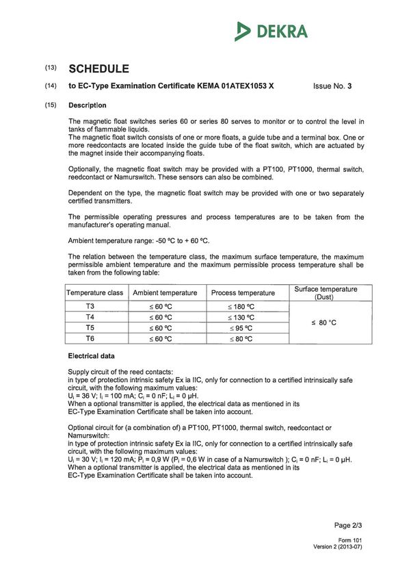
Technische Daten
Übersicht über die elektrischen Daten der zugelassenen Ausführungs-
varianten Schwimmer - Magnetschalter Typ 60... - 80...
Grundtyp Code1 Code2 Code3 Code4 Code5 Code6 Umax / Zündschutzart
Imax
60 .. G.. .. L... /.. ... 36V / Ex ia IIC
100mA T3...T6
80 .. DN..PN.. .. L... /.. ... 36V / Ex ia IIC
100mA T3...T6
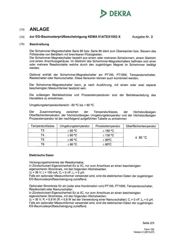
7 / 31Temperaturen Schwimmer – Magnetschalters Typ 60... - 80...
Temperatur Maximale Maximale Maximale Kategorie 2D Staub Maximale
klasse Oberflächen- Prozess- Umgebungstemperatur Oberflächentemperatur bei
temperatur temperatur am Gehäuse Einsatz im Bereich der Zone 21
T3 200°C 180°C 60°C
T4 135°C 130°C 60°C
T≤ +80°C*
T5 100°C 95°C 60°C
T6 85°C 80°C 60°C
*Die maximale Oberflächentemperatur des Betriebsmittel hängt auch von den Betriebstemperaturen des Fluids und der
Umgebungstemperatur ab und muss unterhalb der Zündtemperatur liegen.
Typcode Schwimmer-Magnetschalter Typ 60... - 80...
Typcode Schwimmer
Code 1 Code 2 Code 3 Code 4
V 52 A ...
Code 4
Schwimmerinnenrohr Ø
38 *a Nur für 120 Schwimmer mit
Schwimmerinnenrohr 38mm
Code 3
Magnetsystem
R = Radial
A = Axial
Code 2
Schwimmerdurchmesser
Schwimmercode alt
Grundtyp Material Ausführung
44 S K
Siehe Typcode Material
52 S
62 S A
80 S B23
83 S B
98 S C
105 S D
120 S F
120*a S F38
200 S 200
300 S 300
* alle Maße in mm
Code 1
Material
V Edelstahl
T Titan
HC Hastelloy HC
HB Hastelloy HB
8 / 31Typcode Schwimmer-Magnetschalter
Grundtyp Code 1 Code 2 Code 3 Code 4 Code 5 Code 6 Code 7 Code 8
60 A F / V / .../.... W90/80 V SÖU L.../12 V52A...
Code 8:
Zulassungen *2
EX ATEX Zulassung
EX DNV ATEX und DNV
EX GL ATEX und GL
Code 7:
Schwimmertyp
Siehe Typschlüssel Schwimmer
Code 6:
L.../...= Gesamtlänge des Gleitrohres /
Rohrdurchmesser
Code 5:
Kontaktfunktion / Namurbeschaltung / *Zusatzcode (Die
Buchstabenanzahl des Codes ergibt die Kontaktanzahl)
S Schließer bei steigendem Niveau
Ö Öffner bei steigendem Niveau
U Umschalter
.../ N Namurbeschaltung DIN EN 60947-5-6*
*(Angabe nur wenn Option vorhanden)
Code 4:
Gleitrohrwerkstoff
V = Edelstahl ; HB = Hastelloy B ; HC = Hastelloy C ; T = Titan
Code 3
W.../... Winkelangabe/Winkelänge (nur wenn Option vorhanden)
Code 2
Prozessanschluss: Werkstoff / Größe/ Druck / Flansch Dichtfläche
Flansche FV/.../.../.. F/ Werkstoff/ (Zahlenwert Größe.../Druck...)/ Dichtfläche
DN50 – DN250 bzw. Ansi 1 – 6 / PN6 – PN64 bzw. 150lbs –
600lbs
FV130 = (KSR Ronde – PN40)
Triclamp FCV... FC/ Werkstoff/ (Zahlenwert Größe...)
DN10 – DN100; 1-4 Zol
Milchrohrver- MRV... MR/ Werkstoff/ (Zahlenwert Größe...)
schraubung DN10 – DN150
Einschraub- RV... R/ Werkstoff/ (Zahlenwert Größe...)
gewinde G1 “ – G3 “
INGOLD ISV IS / WERKSTOFF (max. 4 bar)
Stutzen
Werkstoff:
.../V/... = Edelstahl
.../HB/... = Hastelloy B
.../HC/... = Hastelloy C
.../T/... = Titan
Code 1:
A = Ausführung mit Aluminiumgehäuse
APL = Ausführung mit Polyestergehäuse
AV = Ausführung mit Edelstahlgehäuse
AV6 = Ausführung mit Edelstahlgehäuse
AV7 = Ausführung mit Edelstahlgehäuse
AV9 = Ausführung mit Edelstahlgehäuse
Grundtyp
60
9 / 31Schwimmer - Magnetschalters Nenndruck
Prozessanschluss
Grundtyp 80 Grundtyp 60
Flanschangabe Nenndruck in bar Stopfen Nenndruck in bar
PN 6 6 bar
Bei maximaler Gewinde -
PN 16 16 bar einschraublänge und geeigneter
Dichtung am Prozessanschluss gilt
G1 – G3
PN 40 40 bar
die Druckangabe des Schwimmers.*
PN 64 64 bar
* Bei Verwendung des Schwimmer
150 lbs 15 bar (bei max 148°C) ST/0,8, in Verbindung mit
300 lbs 38 bar (bei max 148°C) Nenndruck 64 bar müssen spezielle
Stopfen verwendet werden
600 lbs 77 bar (bei max 148°C)
Sollten die Druckangaben von Prozessanschluss (z.B. Flansch) und Schwimmer differieren, ist die niederste
Druckangabe, Nenndruck des Schwimmer - Magnetschalters.
KSR-Schwimmer
Typ Typ alt Max. Typ Typ alt Max. Typ Typ alt Max.
Betriebs- Betriebs- Betriebs-
druck druck druck
[bar] [bar] [bar]
V44A SVK 16 T83A STB 25 HB44A SHBK 16
V52A SV 40 T80A STB23 25 HB52A SHB 40
V62A SVA 32 T98A STC 25 HB62A SHBA 32
V83A SVB 25 T105A STD 25 HB83A SHBB 25
V80A SVB23 25 T120A STF 25 HB80A SHBB23 25
V98A SVC 25 HC44A SHCK 16 HB98A SHBC 25
V105A SVD 25 HC52A SHC 40 HB105A SHBD 25
V120A SVF23 25 HC62A SHCA 32 HB120A SHBF23 25
V120A/38 SVF38 25 HC83A SHCB 25 HB120A/38 SHBF38 25
V200A SV200 16 HC80A SHCB23 25 HB200A SHB200 16
V300A SV300 16 HC98A SHCC 25
T44A STK 16 HC105A SHCD 25
T52A ST 25 HC120A SHCF23 25
T52A/0,6 ST/0,6 40 HC120A/38 SHCF38 25
T52A/0,8 ST/0,8 40 HC200A SHC200 16
T62A STA 25
10 / 31English
Symbol legend
The following symbols are used in these operating instructions:
Warning
Instructions on correct installation and proper operation of the
Float Switch 60…-80… . Failing to comply with these instructions
can lead to malfunction of or damage to the switch.
Precaution
Instructions which must be complied with to avoid injury or
property damage or loss of the type permit.
Information
Facts and information concerning proper operation of the Float
Switch 60…-80…
Instructions for electrical installation
Information on proper electrical installation.
Safety information
Read these instructions before installing the Float Switches 60…-80… and putting
then into operation.
These instructions are intended for the specialists in charge of mounting, installation and setup.
Comply with the relevant safety regulations when using the equipment.
Unauthorized access and impermissible use of the equipment will result in the loss of guarantee
and liability protection.
Measures must be taken to prevent risks to persons and property in the event of a defect in the
Float Switches 60…-80… .
Do not install in ferromagnetic surroundings or the immediate vicinity of strong electromagnetic fields.
(minimum distance: 1 m).
Float Switches 60…-80… must not be exposed to heavy mechanical loads.
Comply with the maximum current and voltage values for intrinsically safe operation as specified in
the installation and operating instructions.
11 / 31Danger!
There is a risk of poisoning or suffocation when working in containers. Relevant
personal protection measures (e.g. respiratory devices, protective clothing, etc.)
must be taken before work is carried out.
Danger, risk of explosion!
An explosive atmosphere may develop in a container. Measures must be taken to prevent
sparking. Work in such areas must be done by qualified personnel in accordance with the
relevant safety regulations and guidelines.
Application and field of use
An approval has been issued for the Float Switches 60…-80… for use as explosion-protected
equipment within the scope of application defined by EU Guideline 94/9/EU in hazardous areas.
They comply with the specifications regulating use of electrical equipment in explosion risk areas.
The technical data in these operating instructions must be complied with.
Ignition protection type II 1/2 G Ex ia IIC T3...T6 Ga/Gb
II 2 D Ex ib IIIC T80°C Db
Float and Guide tube, zone 0
Structure and functional description
The Float Switches 60…-80… are used to monitor filling levels in containers holding liquid
mediums. These mediums must not contain heavy soiling or coarse suspended matter must not
show a tendency to crystallize out.
KSR Magnetic Float Switches are used to control distinct levels of a liquid. They are based on the
float principle with individual contacts for every level to be monitored.
A float with a built-in magnetic system actuates a small reed contact through the wall of the guide
tube. Thus the switching operation is without direct contact to the liquid, free of wear and tear, and
does not require any power supply.
KSR Magnetic Float Switches are available with multiple switch points.
Removal of transport packaging and transport safety devices
Remove the Float Switch carefully from the transport packaging.
See the instructions on the shipping packaging; remove all transport safety devices before
removing the Float Switch.
Never forcibly remove the Float Switch from the packaging by taking hold of the guide tube!
Before installing the Float Switch, the float safety bands must be removed. Make sure all
packaging components have been removed and that the float moves freely on the guide tube.
12 / 31Installation in the container
The Float Switches are installed in the container using flanges or mounting plugs. (See
the type designation on the product for the specific design of your Float Switch)
Prior to installation, make sure the installation opening in the container agrees in size and
dimensions with the installation option of the Float Switch.
Depending on the design of the Float Switches 60…-80…,
the guide tube is inserted into the container from the 1
outside. Installation should be vertical. To ensure proper
2
functioning, the angle of installation must not deviate
exceed 30° from the vertical position. 3
4
The guide tube of the Float Switches 60…-80… is inserted
into the container from the outside through the installation
opening. It is then fixed by tightening the thread or the 5
screws for flanged versions.
In Float Switches featuring a mounting plug,
6
the thread must be screwed in for the entire
length of the thread.
Float Switches featuring flanges must be
7
installed using suitable bolts, washers and nuts. 8
Please comply with the maximum torque ratings of the
bolts / screws used when tightening them down. max. 30°
Use suitable gaskets. Make sure the gasket material is
resistant to the medium and its vapours as well as to the
expected temperature and pressure loads. 1 Terminal Box
2 Cable gland
3 Process Connection
Designs, where the float’s diameter is lager then the core 4 Gasket
opening must be installed with the float removed form the 5 Guide tube
guide tube. 6 Float
7 Teflon washer
8 Set collar or Tension
Procedure: clamp
1. Mark the upper side of the float (e.g. with "top") Fig. Float Switch…
2. Mark position of the set collar to be removed
3. Remove set collars and teflon washer
4. Remove floats
5. Install Float Switch 60…-80…
6. Position the floats, set collars and teflon washer from inside the container. Mind the marked
positions!
The purpose of the teflon washer is to avoid potential ignition sparking if the
float should fall against the set collar. Operating the equipment without teflon
washer is not permitted.
13 / 31Maximum length of guide tubes
In containers in which turbulences can be expected, Float Switch over 3,000 mm long
must also be secured so as to prevent the Guide tube from bending.
This can be achieved, for instance, with a receiving sleeve at the bottom of the
container.
Electrical connection
Float Switches 60…-80… must only be operated on certified intrinsically safe control
circuits of ignition protection type Ex ia.
Float Switches 60... - 80... Ex ia
The electrical data on the type plate and the additional regulations governing intrinsically safe
circuits must be complied with. This work must be done by trained specialist personnel.
The electrical connection of the Float Switches 60…-80… is realized with integrated terminals.
See the connection diagram inside the terminal box or included with the equipment, or the
information in catalogue 1003-… for the applicable connection scheme.
Selecting the connection cable
The connection cable must be selected as suitable for the expected ambient
conditions (temperature, aggressive atmosphere, weathering, etc.).
The number of wires depends on the number of switching points.
wires
switching point Closing /
Change over
Opening
1 3 4
2 5 7
3 7 10
4 9 13
See the relevant connection scheme in each case.
The connection is to be done with cable marked in light blue. The diameter of the connection cable
must be within the clamp range of the cable gland. If other cable diameters are used, moisture and
dust may penetrate into the equipment.
Use of single bunched conductors is not permissible!
Conduction capacity and inductance
When determining the required cable length, the maximum permissible inductances and
capacities of the connected intrinsically safe control device must be taken into account.
These values should not be exceeded by the connection cable.
14 / 31Cable Connection
1. The connection cable must be laid in accordance with the applicable regulations applying to
installation of intrinsically safe circuits
2. Remove the lid of the terminal box
3. Insert the cable through the cable gland collet into the terminal box
4. Remove jacketing and expose strands
5. Attach terminal lugs to the strands
6. Insert the wires into the row terminals as per diagram and fasten them down
7. Replace and fasten down the terminal box lid
Use the appropriate connection scheme
Equipotential bonding and PE connection
There is at least one PE connection terminal for connection of a PE conductor in the
terminal box of the Float Switch 60…-80….
In the case of Float Switches without external ground terminals, an electrical connection must be
established between the mounting plug and the container during installation. If there is a ground
terminal, the equipotential bonding or PE connection can be realized by this means.
Maintenance
Float Switches 60…-80… function free of maintenance if used properly. However, they must be
subjected to a visual check within the framework of regular inspection, including a container
pressure test.
Special conditions for safe use
If floats of titanium are used, care should be taken, that these float even if it is a rare
occurrence cannot create any sparks through friction or impact.
eleminated.
By the installation is a distance between connecting box and medium to gaurantee the permissible
ambiente temperature range.
15 / 31Functional test
The functional test serves to determine the proper function of the reed contacts.
Functional test prior to installation in the container
Before the Float Switch is installed, it can be checked with a continuity checker or an ohmmeter.
1. Connect the wires of the switch
point to be tested to the
continuity checker or ohmmeter.
2. Raise float and move it up to the
switch point position. Depending
on the switching function, L1
continuity or no continuity will be
indicated.
3. Move float back to initial L2 Float raised
position. The switching function
must be reversed.
4. Repeat steps 1-3 for each Float at initial
switching point. position
Important:
The switching point dimensions L…
refer to the gasket area and the
distance to the middle of the float.
Functional test of installed Float Switch
1. The functionality of installed Float Switches can only be tested from the inside of the container
2. It is recommended to de-install the Float Switch for the functional test
3. Disconnect electrical connections
4. De-install Float Switch
5. Functional test as per chapter "Prior to installation in container"
6. Install Float Switch in the container
7. Re-establish electrical connection as per the relevant connection scheme
Functional testing may trigger unintended reactions in subsequent control
circuits. Risk of property damage or personnel injuries.
16 / 31Error search
The following table lists the most frequent causes of error and the necessary
countermeasures
Error Cause Countermeasure
Compare with
False terminal connection
connection diagram
Insulation Check terminals
Set collars out of position
No switching
or replaced incorrectly Control position of set
function or
after the guide tube is collar
undefined
removed
Reed contact defective
due to mechanical Return to factory
vibrations
Float installed incorrectly Turn float around
False switching
False ordering Please contact the
point dimensions
information factory
Reworking of
Thread or flange
container
dimensions of Float
Reworking of Float
Float Switch cannot Switch do not agree
Switch at factory
be attached at the
Reworking of thread
intended position on Thread of mounting plug
or replacement of
the container on container defective
mounting plug
Bolt threading on the
Send back to factory
Float Switch defective
Please give us a call in case of any difficulties. We will do everything we can to
provide you with the required advice and help.
Technical data
Summary electrical data on Float Switch variants with permit
Basic Code1 Code2 Code3 Code4 Code5 Code6 Umax / Tmax Ignition
type Imax protection
type
60 .. G.. .. L... /.. ... 36V / 180˚C Ex ia IIC
100mA T3...T6
80 .. DN..PN.. .. L... /.. ... 36V / 180˚C Ex ia IIC
100mA T3...T6
17 / 31Temperatures - Float Switch 60…-80…
Temperature Maximum surface Maximum Maximum ambient Category 2D Dust maximum
class temperature process - temperature on surface temperature for use in
temperature terminal box area Zone 21
T3 200°C 180°C 60°C
T4 135°C 130°C 60°C
T≤ +80°C*
T5 100°C 95°C 60°C
T6 85°C 80°C 60°C
*The maximum ambient temperature of the equipment is also dependant from the operating temperature of the fluid and
the ambient temperature and has to be below the ignition temperature.
Type Code Float Switch 60…-80
Type Code Float
Code 1 Code 2 Code 3 Code 4
V 52 A ...
Code 4
Float ID in mm
38 *a Only for 120 Float with
Float ID 38mm
Code 3
magnet system
R = radial
A = Axial
Code 2
Float OD in mm
Old float type code
Basic type Material Version
44 S K
52 S
See type code material
62 S A
80 S B23
83 S B
98 S C
105 S D
120 S F
120*a S F38
200 S 200
300 S 300
* all dimensions in mm
Code 1
Material
V Stainless steel
T Titanium
HC Hastelloy HC
HB Hastelloy HB
18 / 31Type Code Float Switch
Basic type Code 1 Code 2 Code 3 Code 4 Code 5 Code 6 Code 7 Code 8
60 A F / V / .../.... W90/80 V SÖU L.../12 V52A...
Code 8:
Zulassungen *2
EX ATEX Zulassung
EX DNV ATEX und DNV
EX GL ATEX und GL
Code 7:
Float
see Type Code Float
Code 6:
L.../...= Guide tube length max. / Guide tube - OD
Code 5:
Contact separation / NAMUR / * Optional code (The number of
letters in the code corresponds to the number of contacts)
S Closing on rising level
Ö Opening on rising level
U Contact separation on rising level
.../ N acc. to NAMUR DIN EN 60947-5-6 *
*(only if Option available)
Code 4:
Guide tube material
V = Edelstahl ; HB = Hastelloy B ; HC = Hastelloy C ; T = Titan
Code 3
W.../... Winkelangabe/Winkelänge (nur wenn Option vorhanden)
Code 2
Process connection / Material / nominal size (pressure rating )/ Flange face
Flange FV/.../.../.. F/ Material/ (numerical value nominal size.../ pressure rating...)/ Flange face
DN50 - DN250 or Ansi 1 – 6 / PN6 - PN64 or 150lbs - 600lbs
Triclamp FCV... C/ Material / (numerical value nominal size.../ pressure rating...)
DN10 - DN100; 1-4 Zol
Dairy fitting MRV... MR/ Material / (numerical value nominal size.../ pressure rating...)
acc. to DIN DN10 - DN150
11851
Mounting RV... R/ Material / size
thread G1 " - G3 "
Sanitary ISV IS / Material (max. 4 bar)
nozzle (Sanitary nozzle / Ingold nozzle)
Material:
.../V/... = Stainless steel
.../HB/... = Hastelloy B
.../HC/... = Hastelloy C
.../T/... = Titanium
Code 1:
A = Version with terminal box Aluminium
APL = Version with terminal box Polyester
AV = Version with terminal box Stainless steel
AV6 = Version with terminal box Stainless steel
AV7 = Version with terminal box Stainless steel
AV9 = Version with terminal box Stainless steel
Basic type
60
19 / 31Float Switchnominal pressure
Process connection
Basic type 80 Basic type 60
Mounting Nominal pressure in bar
Flange Nominal pressure in bar
Thread
PN 6 6 bar
In cases of maximum bolt threading
PN 16 16 bar length and suitable gaskets at the
process connection, the float
G1 – G3
PN 40 40 bar
pressure specification applies.*
PN 64 64 bar
* When float ST/0.8 is used, special
150 lbs 15 bar (at max 148°C) mounting threads have to be used
300 lbs 38 bar (at max 148°C) in connection with a nominal
pressure of 64 bar.
600 lbs 77 bar (at max 148°C)
If the pressure specifications for the process connection (e.g. flange) and float differ, the lowest
pressure figure is then the nominal pressure of the Float Switch.
KSR float
Type Type Max. Type Type Max. Type Type Max.
old operating old operating old operating
pressure pressure pressure
[bar] [bar] [bar]
V44A SVK 16 T83A STB 25 HB44A SHBK 16
V52A SV 40 T80A STB23 25 HB52A SHB 40
V62A SVA 32 T98A STC 25 HB62A SHBA 32
V83A SVB 25 T105A STD 25 HB83A SHBB 25
V80A SVB23 25 T120A STF 25 HB80A SHBB23 25
V98A SVC 25 HC44A SHCK 16 HB98A SHBC 25
V105A SVD 25 HC52A SHC 40 HB105A SHBD 25
V120A SVF23 25 HC62A SHCA 32 HB120A SHBF23 25
V120A/38 SVF38 25 HC83A SHCB 25 HB120A/38 SHBF38 25
V200A SV200 16 HC80A SHCB23 25 HB200A SHB200 16
V300A SV300 16 HC98A SHCC 25
T44A STK 16 HC105A SHCD 25
T52A ST 25 HC120A SHCF23 25
T52A/0,6 ST/0,6 40 HC120A/38 SHCF38 25
T52A/0,8 ST/0,8 40 HC200A SHC200 16
T62A STA 25
20 / 31Français
Légende
Les symboles suivants sont utilisés dans ce mode d’emploi:
Avertissement
Instructions pour un montage correct et une mise en service
conforme des régulateurs de niveau type 60… resp. 80… Une
non-observation de ces instructions peut conduire à des erreurs
de fonctionnement ou à des détériorations.
Danger - Précautions
Instructions dont la non-observation peut conduire à des dégâts
corporels ou matériels.
Information
Indications et informations pour une utilisation appropriée des
régulateurs de niveau type 60… resp. 80…
Instructions pour l’installation électrique
Informations pour une installation électrique appropriée.
Instructions relatives à la sécurité
Veuillez lire ces instructions avant l'installation et la mise en service des régulateurs
de niveau type 60… resp. 80…
Ces instructions sont destinées à un personnel qualifié qui va réaliser les travaux de montage et
d'installation.
Veuillez respecter les règles de sécurité appropriée lors de l’installation.
Une intervention non autorisée et une utilisation interdite entraînent la perte de la garantie et de la
possibilité de recours à des réclamations.
Veuillez prendre les mesures nécessaires, en cas de panne sur les régulateurs de niveau type
60… resp. 80…, pour éviter des risques pour le personnel et le matériel.
Veuillez ne pas installer les régulateurs de niveau type 60… resp. 80… à proximité de puissants
champs électro-magnétiques (1 m de distance minimum).
Les régulateurs de niveau type 60… resp. 80… ne doivent pas subir de contraintes mécaniques
importantes.
Les valeurs électriques maxi indiquées dans le mode d’emplo et appropriées à l’utilisation en
sécurité intrinsèque doivent être respectées.
21 / 31Danger!
Lors de travaux dans un réservoir, il existe un danger d'empoisonnement ou de
suffoquement. Ces travaux ne peuvent être entrepris qu'en application de
mesures de sécurité adaptées aux personnes (par exemple port de masque
respiratoire, vêtements de protection ou équivalent).
Attention, danger d'explosion!
Il peut exister un risque de formation d'atmosphère explosive dans un réservoir. Il faut alors
prendre les mesures nécessaires afin d’éviter la formation d'étincelle. Seulement un
personnel qualifié et formé aux exigences relatives aux directives de sécurité pourra
intervenir dans de telles zones.
Utilisation et domaine d'application
Les régulateurs de niveau type 60… resp. 80… sont des appareils protégés contre les risques
d’explosions cconformément à la directive européenne 94/9/CE et, à ce titre, ils sont homologués
pour l'installation dans des zones explosives.
Ils répondent aux exigences des appareils électriques pour zones explosives.
Les caractéristiques techniques données dans ce mode d’emploi doivent être respectées.
Type de protection: II 1/2 G Ex ia IIC T3...T6 Ga/Gb
II 2 D Ex ib IIIC T80°C Db
Flotteur et tube de guidage zone 0
Principe et description de fonctionnement
Les régulateurs de niveau type 60… resp. 80… servent à contrôler le niveau des liquides dans les
réservoirs. Ces liquides ne doivent pas contenir de particules solides et ne doivent pas être enclins
à la cristallisation.
Les régulateurs de niveau travaillent selon le principe du flotteur avec transmission magnétique. A
l'intérieur du tube de guidage, se trouvent un ou plusieurs interrupteurs à lame souple (contacts
sous gaz inerte). Sur le tube de guidage sont montés un ou plusieurs flotteurs. Leur position est
fonction du niveau du liquide à contrôler. Un aimant permanent est monté à l'intérieur de ces
flotteurs. Dès que le champ magnétique atteint le domaine d'action de l’interrupteur à lame souple,
ce dernier est actionné. Le nombre et la position des flotteurs dépend du nombre de contacts, de
leur fonction ainsi que de leur position. Veuillez consulter la grille de code pour les différentes
variantes.
Enlèvement des emballages et des accessoires de fixation nécessaires au transport
Les régulateurs de niveau doivent être déballés avec précaution.
Veuillez tenir compte des instructions figurant sur l'emballage et enlever tous les accessoires de
fixation avant de sortir le régulateur de son emballage.
Ne jamais forcer sur le tube de guidage pour extraire l'appareil de son emballage!
Avant le montage du régulateur de niveau, veuillez ôter les bandes de fixation des flotteurs.
Assurez-vous que toutes les fixations et emballages nécessaires au transport ont bien été enlevés
et que le flotteur coulisse librement sur le tube de guidage.
22 / 31Sie können auch lesen