S-MATCH The Balanced Universal ATU
←
→
Transkription von Seiteninhalten
Wenn Ihr Browser die Seite nicht korrekt rendert, bitte, lesen Sie den Inhalt der Seite unten
2012-09-01                                                smatcheng

                         S-MATCH© The Balanced Universal ATU
                         (PA0FRI's "S-MATCH ATU" published in RSGB's RadCom March 2003 and VERON's ELECTRON November 2003)

                                                                        12-02-2012

                                                                 How the idea arose.

                                                  Micro Metals/Amidon toroids suitable for this ATU.

                                                       This idea has not yet been fully tested.

pa0fri.home.xs4all.nl/ATU/Smatch/smatcheng.htm                                                                               1/22
2012-09-01                                                     smatcheng
                                                                       A 1500 W S-Match.

                          A model of the third variation
                                                                                 Home brewed with cleaned and painted components from the junk box.

                                                                                With this system it was possible to match for SWR = 1 on
                                                                                all 9 HF bands with respective a 2 × 17 dipole and a
                                                                                W3DZZ. Both antennas were feed with approximately 10 m
                                                                                ladder line.

                                                                                Undoubtedly a G5RV can be matched for SWR = 1.

     S-MATCH©

                              .

                                                           Several possibilities of the S Match design.

pa0fri.home.xs4all.nl/ATU/Smatch/smatcheng.htm                                                                                                    2/22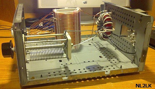
2012-09-01                                             smatcheng

                                                                        I was regularly asked whether my system can be applied
                                                                        as an anode circuit for a RF amplifier. It is also possible,
                                                                        but due to lack of time I was not able to test the circuit
                                                                        with high power to fully support the idea. That is a
                                                                        good opportunity for you to try it out.

                                                                                                   After an extensive research and
                                                                                                   experimenting I achieved the
                                                                                                   design shown in the above
                                                                                                   drawings of the Balanced
                                                                                                   Universal ATU System. To
                                                                                                   make it distinctive from other
                                                                                                   types of ATU's, I call my
                                                                                                   design S-Match©. The system
                                                                                                   is intended to accommodate
                                                                                                   balanced    antenna systems
     transmitting on a very wide frequency spectrum, ranging from 160 m band up to 10 m band. Likewise, it is able to take
     proper care of impedances and associated reactances ranging from less than 20 Ω and up to 3000 Ω. Built with the
     proper components, it is able to transfer loads of more than 1000 Watts. This balanced antenna-tuning unit has only
     three components: a capacitor, a roller inductor and a balun or RF transformer. The input circuits are isolated from the
     output circuits, resulting in a system, which is suitable also for single-wire antennas and coax fed antennas.

     The efficiency of mechanical and electrical a
     well-built S-Match is equivalent to other ATU's
     in this (fig») table. See my Test Symmetrical
     ATU's.

pa0fri.home.xs4all.nl/ATU/Smatch/smatcheng.htm                                                                                   3/22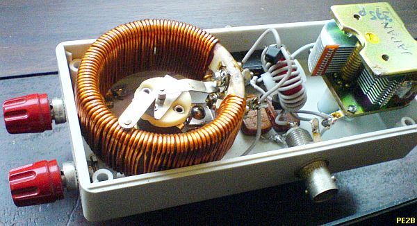
2012-09-01                                                  smatcheng

     In the design of one of my ATU’s, the balun using T200A-2 toroid is mounted between two PCB disks and located in
     between the 50 µH roller-inductor and the 12 – 1200 pF vacuum capacitor.

     An antenna like my present antenna system is matched using only 200 pF on all nine HF bands, still my S-Match is built
     with a 1200 pF vacuum capacitor. My ATU was able to match easily the antennas of a couple of friends. In one case it
     was barely adequate to match another friend's 4 × 40m loop antenna on 160 m. I had to add an extra switchable 1200
     pF capacitor in parallel with the roller inductor to handle any impedance. (see further below)

     CAPACITANCE

                                                   With some antenna systems a better efficiency may be achieved if the antenna is
                                                   connected to the capacitor as shown in the drawing by the dotted line. It is also
                                                   possible to use two separate toroids. I didn’t notice any difference between an
                                                   ATU with two cores and an ATU built with a single toroid.

     TRANSFORMER

             Transformers made with Amidon toroids. The T200A-2 toroid is a nearly exact substitute of two T200-2 units sandwiched together.

pa0fri.home.xs4all.nl/ATU/Smatch/smatcheng.htm                                                                                                 4/22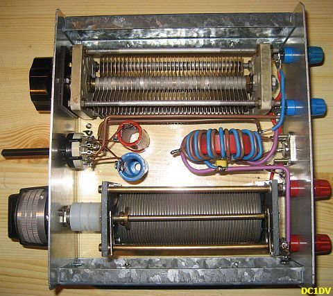
2012-09-01                                                  smatcheng

                     ATTENTION: Do not twist the black and green wire!

             The inductance of the turns is a part of the resonant
             circuit with the roller-inductor and the capacitor.

                                                                                Wires are twisted for more thickness.

                                                                          The rule-of-thumb for the windings is:
                                                                         ATU for 10 – 160 m: (a-b) = (c-e) + (f-d) = ~3 µH

                                                                          ATU for 10 – 30 m: (a-b) = (c-e) + (f-d) ≤ 3 µH

                                                                          ATU for 30 – 160 m: (a-b) = (c-e) + (f-d) ≥ 3 µH

     The transformer contributes a lot to the final result, which is my conclusion after I tested many types of windings. A
     couple of ham friends successfully tested a number of my own ideas for a suitable HF transformer/balun. The above
     chosen type of transformation ensures that input and output connections are galvanic isolated. The experiments show
     that an inductance of about 3 µH is a good compromise for all HF bands. Sometimes the minimum inductance (coil +
     balun) is too large for some 10-30 m antenna systems. Subsequently, extending or shortening the feeding line was
     necessary to change the antenna system impedance to cope with the tuner, or build a separate ATU with fewer turns e.g.
     less than 3 µH on the toroid.

     The transformer/balun is part of the tuning system. Most ferrite toroids are not suitable for high power or high RF current
     while the indicated Amidon iron powder core is.

pa0fri.home.xs4all.nl/ATU/Smatch/smatcheng.htm                                                                               5/22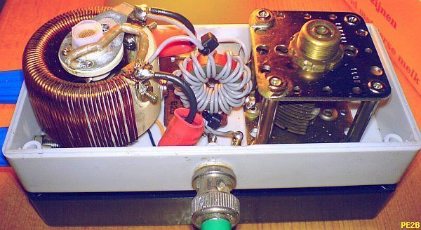
2012-09-01                                                    smatcheng

                      The sequence of the windings. Left side: blue = input, black & red = capacitor. Right side: black & red = inductor.

     The windings should provide high-voltage insulation by using Teflon covered
     wire. Another option would be to use RG58 coax cable with the outer isolation
     and screen stripped off. Do not twist the wires of the primary windings with
     the wires of the secondary windings. In the picture (see fig») the light blue
     with the blue wires.

     "PIG NOSE" BALUN
     RZ3AE's S-Match ATU

     RZ3AE has sent me an email with attachment: "Your idea for a balanced tuner allows for a very interesting design. A
     translated part of his Russian article, he wrote:" With the unconventional design and the use of special components a
     small symmetrical tuner may be created.

pa0fri.home.xs4all.nl/ATU/Smatch/smatcheng.htm                                                                                              6/22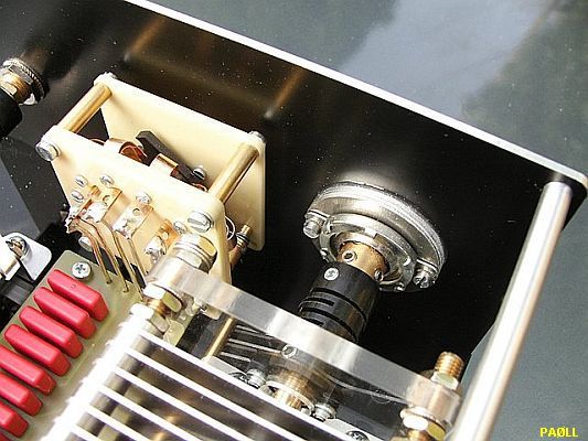
2012-09-01                                            smatcheng

     The balun in the original design was replaced with two stacked ferrite tubes of
     high permeability and the roller inductor by a T200-2 toroidal coil with 15
     taps. Taps 1 through 3 one turn, 4 to 6 two turns, 7 and 8 three turns, and 9
     to 15 four turns evenly distributed over the rest of the toroid.

     The balun is suitable for an output less than or equal to 100 W and the wire is
     insulated with Teflon.                                                            RZ3AE used two ferrite tubes as balun.

     The various amateur bands may be adjusted to 600 Ohm with VSWR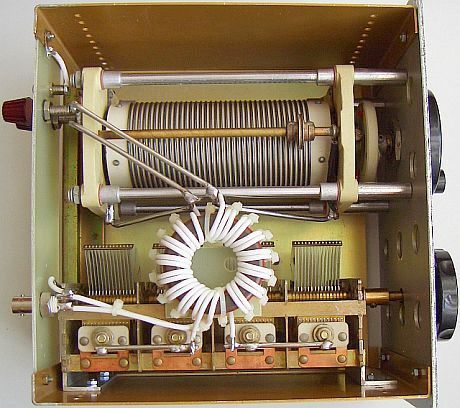
2012-09-01                                            smatcheng

     IMBALANCE

     If any unbalance occurs, try switching to the other connection or interchange the connections to the roller inductor.

     My experience shows that some unbalance in an ATU occurs due to the construction and the location of the components.
     For example, a variable capacitor has frame and movable plates, which are not in any balance with respect to the chassis
     or system ground. The basic mechanical construction of roller coils is also not symmetrical.

     Always begin with matching the system for SWR = 1, to obtain maximum balance. Unbalance is usually the result of
     inaccurate tuning. With the usual baluns it may look as if the feeding line is symmetrical, but the centre taps of the bifilar
     and trifilar wound toroids force the balance with respect to "ground" or chassis (fig.a).

     Some Internet sites state that in comparison tests
     the S-Match failed regarding balance. The authors
     brought no evidence whether the balance of the
     "reference" ATU was tested properly….

     You can conduct proper tests if your feeder line is in
     balance with real ground. Use the S-match or any
     other unbalanced tuner for the test. Connect one of
     the feeder lines to the ATU (fig. c), match for lowest
     SWR and measure the RF current. Repeat the test
     with the other end of the feeder line (fig. d). Check
     and mark whether both currents are equal or not. As
     a "ground" you can use a single wire in the backyard
     or a wire to your central heating system.

     INDUCTORS WITH SWITCHED TAPS
                                                 The use of a roller inductor enables tuning only by turning knobs. Some hams
                                                 don’t like roller coils, not realising that a switched inductance with many taps
                                                 has a lot more self-capacitance and self-inductance. Most of the time you can’t
                                                 achieve a proper adjustment because the needed point is somewhere in
                                                 between the taps. Still, I provide in this present application a switched
                                                 inductance of 25 µH, which will be adequate for most of the antenna systems.
                                                 An extra variable capacitor of 470 pF from a vintage AM receiver can be added
                                                 in series with the input to help reducing the VSWR.

pa0fri.home.xs4all.nl/ATU/Smatch/smatcheng.htm                                                                                  8/22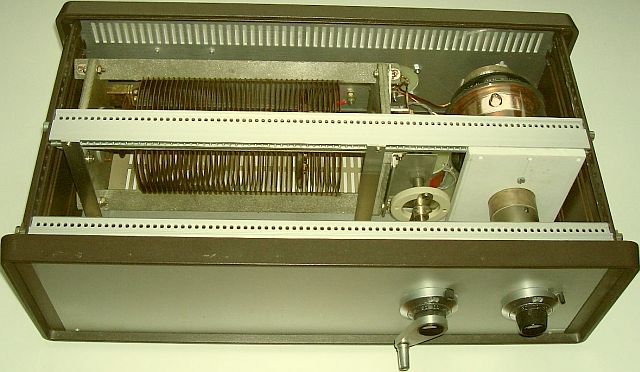
2012-09-01                                         smatcheng

     REPEAT TESTING
     The earlier made notes had been lost and it was decided to repeat the testing of the different designs to determine which
     one was the best solution. At the same time it was investigated to see if there was even a better solution than those
     known to-date. A temporary set-up, shown below, was used.

     There was hardly any
     difference in the efficiency
     of any of the four
     designs. Afterwards the
     symmetry became the
     focus. The settings of the
     S-Match need to be
     adjusted for a SWR = 1
     between the transmitter
     and the ATU in order to
     achieve the best possible
     balance. When this was
     done, design figure 2
     showed to be the better
     one for use on the
     frequencies between 1.8                               At present my favourite systems are fig 2 and fig 5.
     MHz and 10.150 MHz.
     Design figure 3 showed to have the best symmetry for the frequencies between 14 MHz and 30 MHz. No sound
     explanation has been discovered for this difference. Design fig.2 requires slightly more inductance than design fig.3
     (which has the antenna parallel to the capacitor). Between 14 MHz and 30 MHz the higher inductance requirement of the
     roller inductor is advantageous. Please refer to the below mentioned comments of a German HAM on using the S-Match
     on the 10 meter band.

     The capacitor can be a split stator with a grounded stator. If the parts are built in a metal or screened cabinet, they
     should be assembled on at least 5 cm distance of all metal parts to minimise the asymmetry of the used components.

pa0fri.home.xs4all.nl/ATU/Smatch/smatcheng.htm                                                                             9/22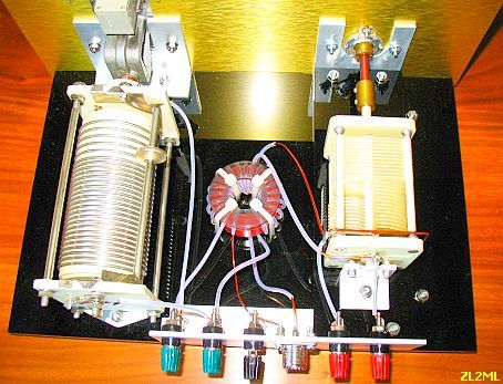
2012-09-01                                                 smatcheng

                                                                                Test of the figure 5 design. The capacitor is suited for a 400 W
                                                                                    ATU but survives a test with 700 W on 80 and 160 m!
              These components were used for the repeated test of the design.

pa0fri.home.xs4all.nl/ATU/Smatch/smatcheng.htm                                                                                                     10/22
2012-09-01 smatcheng
These small caps are suited for at least a 100 W ATU.
Final test Finished
All pictures are just illustrative examples of this S-Match design.
This simple ATU with variable capacitors (from a vintage AM receiver) and a T200-2 toroid is suitable for 400 Watts
(fig»). The matching range can be increased with an extra-switched 100–220 pF/5 kV fixed capacitor and used when the
antenna impedance is below 50 Ω. With my inverted dipole it was necessary to switch-in the fixed capacitor in parallel
with the roller inductor only on the 80 m band.
pa0fri.home.xs4all.nl/ATU/Smatch/smatcheng.htm 11/222012-09-01 smatcheng
CONVERSION
A T-match unit can
easily be converted to
an S-match by
removing the second
capacitor or bypassing
the first capacitor. The free hole in the front panel
of a converted commercial unit can be used for a
switch for paralleling fixed capacitors to the tuning capacitor to provide additional capacitance.
PAØLL
As an encouragement for home brewing see in alphabetical and numerical order examples of S-Match tuners. Not
everyone is just as skilful but it is most important that it works well.
Kees, PAØLL who is famous for his LL-tuners, sent me photographs of his "LL S-Match". There was much demand for a
small portable antenna system including a small ATU. For this reason his intention was to build and sell a handy ATU
inclusive the antenna in a carry box. The final product is built with components, which are made especially for the tuner.
C = 11 - 470 pF (knob with 1 :_6 reduction), L = 34 µH. The ferrite toroid for the balun was specially made by Amidon
for this ATU. I expect that all his handcrafts made ATU's ends as "collector items"!
pa0fri.home.xs4all.nl/ATU/Smatch/smatcheng.htm 12/222012-09-01 smatcheng
PE1KQP's and PE1ADY's S-MATCH
PE1ADY's experimental S-Match for his 2 × 20 m
PE1KQP modified his CL tuner to an S-Match. During test on dipole and 20 m feeder line. He obtained a SWR
field days it turns out that his ATU outperforms many = 1 at 1.8 - 29.5 MHz.
commercial types.
4 × PE2B's S-MATCH
pa0fri.home.xs4all.nl/ATU/Smatch/smatcheng.htm 13/222012-09-01 smatcheng pa0fri.home.xs4all.nl/ATU/Smatch/smatcheng.htm 14/22
2012-09-01                                         smatcheng

     PAØMJM

     The version of PAØMJM's S-Match. The graphics were made with a miniVNA (www.miniradiosolutions.com) program.

     COMMENTARY
     Since I published this design, may hams successfully copy this simple ATU.

pa0fri.home.xs4all.nl/ATU/Smatch/smatcheng.htm                                                                      15/22
2012-09-01 smatcheng
PA3EGH's S -Match
Some of the selected emails are presented:
DJ9XG:
Ich habe wieder einmal etwas von deiner ufb homepage nachgebaut, eine S-Match ATU. Ich habe hier 3 verschiedenen
ATU's und diese auch alle 3 getestet.
1. Drake MN2700 mit externem 1:4 Balun
2. Parallelkreis Koppler ähnlich Johnson oder Annecke
3. S-Match nach PA0FRI
Als Antenne verwende ich hier eine 2 × 20 m Dipol symmetrisch mit 240 Ohm Schlauchkabel (Antennenkabel für UHF-
Fernsehantennen aus den 70er Jahren) gespeist. Antenne hängt zwischen 15 m und 9 m über Grund.
Mit allen 3 Antennen erreiche ich von 160-10 m 1:1 SWR... die Ergebnisse vieler Tests sind folgende Reihenfolge:
1. S-Match auf allen Bändern Nummer 1
2. Parallkreis nach Annecke Nummer 2
3. Drake Tuner Nummer 3
Du siehst dein S-Match ist der beste ATU, hinzu kommt noch die komfortable Bedienung. Ich habe den hier mit einer
riesigen kommerziellen Rollspule 14 µH und einem 20-200 pF Sendedrehko aufgebaut. Als Ringkern verwende ich im
Moment noch 1 Amidon T200-2, werde den aber gegen eine 2 Ringkernlösung mit 2 x T200-2 ersetzen, da der eine Kern
bei 1 kW Output doch etwas warm wird.
Nun zu meinen Beobachtungen mit der S-Match. Bei 160 m benötige ich nur ca 7 µH der Rollspule und ca 400 pF für den
Drehkondensator (ich hatte eigentlich damit gerechnet dass die Rollspule zu wenig Induktivität auf 160 m hat). Bei den
höheren Bändern wird das L natürlich noch kleiner (auf 10 m habe ich noch 1 Windung der Rollspule). Trotz dieser sehr
kleinen Werte ist die S-Match immer noch die beste auf allen (!) KW-Bändern.
DC1DV:
Zunächst einmal möchte ich mich ganz herzlich für Ihre Veröffentlichung zum S-Match im Internet bedanken. Der S-Match
Koppler hat sich zum effizientesten Bastelprojekt seit langem bei mir heraus gestellt. Warum? Nachdem sich mittlerweile
bei mir die verschiedenen Koppler, ähnlich wie bei Ihnen stapeln, sollte man meinen es sei endlich genug. Nichts
dergleichen!
Bei einem Test, neulich mit Peter, DC0DX, auf dem 160m Band, hatte ich mehr aus Spaß meinen S-Match Probeaufbau
(fig») angeschlossen, den ich schon für ein anderes Projekt auseinander reißen wollte. Donnerwetter, das Rauschen war
von fast S7 auf um S2 gesunken, aber Peters Feldstärke blieb mit um die S9 erhalten. Ich traute meinen Augen kaum.
Darüber hinaus bekam ich vom Peter noch einen deutlichen Lautstärkezuwachs bescheinigt. Dieser ließ sich leider nicht
näher spezifizieren („Mit Brille wär´ das nicht passiert…") Schnell also den Antennen-Umschalter her und dann verglichen.
Kein Koppler brachte so tolle Werte.
pa0fri.home.xs4all.nl/ATU/Smatch/smatcheng.htm 16/222012-09-01 smatcheng
So sehr ich mich über
den Erfolg freute, um so
weniger konnte ich mir
auf das so extrem
positive Verhalten einen
Vers machen. Leider bis
heute nicht. Nun stellte
ich mir allerdings die
Frage, ob der S-Mach
Koppler nur an meiner V-
Antenne (2 × 15 m, ca.
40° Öffnungswinkel) so ein gutes Verhalten zeigte. Nirgendwo hatte ich von solchen
schier unglaublich tollen Werten gehört oder gelesen. Also ab in Dieters Garten
(DB3DK) und den neuen dicken HP Vergleichskoppler und den S-Match aufgebaut. 2
× 20 m Antenne. Welche Überraschung: Beide lagen im Empfang absolut gleich!
Abgesehen von der Wirkung an meiner Antenne, zeichnet
sich der Koppler durch seine absolute Einfachheit aus. Der
jetzt von mir aufgebaute kleine Koppler (fig») beinhaltet
neben dem Ringkern einen Drehko (439 pF) von lediglich
1.5 mm Plattenabstand und eine relativ kleine Rollspule (28
µH) a la Annecke. Im abgestimmten Zustand sind 100 W HF
absolut kein Problem. Die zusätzlich schaltbaren
Kondensatoren werden an einer 2 × 20 m langen Antenne
nicht benötigt, bei mir zuhause allerdings doch. Im 80 m
Band brauche ich 1100 pF, wenig L und auf 160 m reicht
der Drehko neben 21 µH der Rollspule. Es funktionieren
übrigens alle Bänder von 160 bis 10 m einwandfrei.
Bleibt noch zu erwähnen, das manchmal die Antenne an den
Drehko gelegte werden muss und manchmal an die
Rollspule. Meist ist der Ausgang an der Rollspule zu nutzen.
Das Abstimmverhalten ist am Drehko spitz wie eine Nadel
und an der Rollspule butterweich. Also bewege ich zunächst
den Drehko in die richtige Richtung und dippe dann mit der
pa0fri.home.xs4all.nl/ATU/Smatch/smatcheng.htm 17/222012-09-01 smatcheng
Rollspule nach. Das Finden der ersten Resonanz ist allerdings leicht schwieriger als beim HP Koppler, aber dennoch gut zu
meistern.
DL1FDL
Your design is very interesting, because it is very easy to build (e.g. for HF beginners), saving
expensive radio parts and it is small in dimensions (e.g. for portable ham activities). In my case I
have used a 34 µH/3 A coil, a 220 pF/2 kV capacitor and a toroid T200-2, enough for more than
100 W power. I am using your S-March concept (fig») now together with my 2 × 12.5m portable
dipole and a 13 m feeder line in the field. It's coupling the antenna in good balance from 80 m to
10 m band in a perfect SWR. It fits perfect the little size of my TS 50.
DL4YEH
Hier mal ein Bild von meiner SMatch ein
Super Sym.Koppler, klappt an meinem
Dipol mit Hühnerleiter wunderbar. Im
vergleich zu Annecke oder MFJ 974HB
besser zu bedienen RX/TX seitig kein
Unterschied festzustellen.
DL5GBL:
Ich habe eben provisorisch Ihren S-Match mit alten Teilen aus der Bastelkiste auf Brett zusammengeloppt und getestet.
Bauzeit: Gerademal eine halbe Stunde (inklusive dem Wickeln der 2 Trafos (T184: 2 × 8 Windungen 1.5 Schaltdraht für
3µH).
Fazit: Alles problemlos!!!- Ich bin restlos begeistert und werde mir ein paar reguläre Geräte davon
bauen.
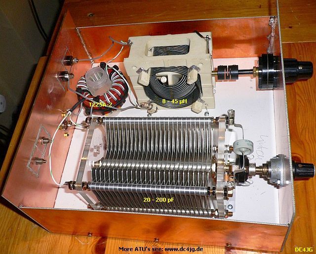
DC4JG:
Ich habe auf deiner Internetseite die
Beschreibung zum S-Match-Koppler
gelesen und den Koppler sofort
nachgebaut. Der Drehko ist ein
Schmetterlings-Drehko 20 bis 200 pf
und das L ist ein Kugelvariometer
mit 8 bis 45 µH. Der Übertrager ist
ein T225A-2. Der S-Match
pa0fri.home.xs4all.nl/ATU/Smatch/smatcheng.htm 18/222012-09-01 smatcheng
funktioniert prima. Ich habe viele
Koppler probiert siehe www.dc4jg.de
aber keiner ging so unproblematisch
wie der S-Match. Ich überstreiche
mit dem kleinen Drehko und dem
Kugelvariometer alle Bänder 160 bis
20 m, der Rest ist nicht probiert.
Aber alles in allem, ein guter
Koppler. Der Koppler ist auch an der
Feederleitung sehr gut symetrisch.
Hier haben schon 3 bis 4 OM´s
diesen Koppler mit Erfolg gebaut.
DO2KH
DC4JG's S-Match built with a T225A-2 toroid and a variometer.
Auch dies wäre eine Variante die man nicht
ausser acht lassen sollte. Betreibe seit mehr
als einen Monat diesen symmetrischen
Koppler. Mitlerweile habe ich den
Testaufbau ordentlich in ein
Plexiglasgehäuse eingebaut. Ich fügte
einen SWR/ Power Messkopf im Eingang
hinzu, sowie Ausgangsseitig einen
Messkopf um die Spannung am Übergang
zur H-Leiter Messen zu können. Er passt
von 160-10 m an. Da ich wissen wollte, ob
es einen grossen Unterschied zwischen
einem symmetrischen Koppler, Schaltung
Palstar, oder nach PA0FRI gibt, baute ich mit zwei Russenspulen und einem Drehko diesen nach, Ergebnis; meine
Gegenstationen konnten keinen Unterschied Feststellen. (Test: wie immer über mehrere Tage, 160, 80, 15 und 10 m, 2 ×
15.60 m (ehemalige G5RV) und 26 m H-Leiter da ich bis zum Shack kommen müsste).
Den leicht und kostengünstige herzustellenden symmetrische Koppler nach PA0FRI kann ich empfehlen, ich konnte keine
Unsymmetrie, Phasenverschiebung messen. (Messender, Koppler, jeweils verschiedene Abschluss R´s der anzunehmenden
impedanz an der H-Leiter und zwei identische Tastköpfe an ein HP Oszi) Beide Koppler verhielten sich nahezu gleich.
pa0fri.home.xs4all.nl/ATU/Smatch/smatcheng.htm 19/222012-09-01 smatcheng
Der Vorteil beim S-Match ist die Grösse und der geringe Kostenfaktor der
Bauteile, man kann ihn auf kleinsten Raum aufbauen, eine Rollspule ist nicht
unbedingt erforderlich, Spule mit Anzapfungen und einem min. 12 Stufigen
Schalter reicht auch.
Wie o. g. reicht ein einfacher Doppeldrehko mit 2 × 500 pF. Für 160 m sollten
dem Drehko min. 100-330 pF paralell hinzugeschaltet werden. Ein Aufbau mit
zwei T200 Kerne («fig) ist auch nicht erforderlich, ich konnte keinen Unterschied
messen bei der Variante mit einem Kern, wiederum ein Bauteil weniger.
DO7DE
Ich habe mir auch denn S-Match mit einem Split-Drehko 2 × 220/1.5 kV, einer RollSpule 15.5µH (1.5 Silberdraht), sowie
2 × T200-2 Rinkerne nachgebaut. Der S-Match macht seine Arbeit von 10 m bis 160 m hervorragend an einem
Symetrischen Dipol! Werde dem S-Mach aber noch ein Kreuzzeiger-Stehwellen-Messgerät hinzufügen in das Gehäuse. Ich
bin super begeistert und kann ihn nur weiter Empfehlen.
NL2LK
ZL2ML
ZL2ML emailed the following:
Initially I had a LDG automatic tuner but at times it just did not match properly. I next build a balanced tuner with two
roller inductors according to the information provided by AG6K in his publication 'A balanced antenna tuner'. This worked
a lot better. But manually turning two mechanically coupled roller inductors is not very light and the design is only a L-C
which means that any impedance's that fall between approx. 37.5 and 75 Ohm need large values of either the capacitor
pa0fri.home.xs4all.nl/ATU/Smatch/smatcheng.htm 20/222012-09-01 smatcheng
or the inductor and hence normally do not get matched properly. (This is also the reason why many automatic ATU's like
the LDG do not tune below a SWR of 1 : 1.5 )
It was a simple matter to test the S-match out (fig») and then I proceeded to
build it properly. Am using a Johnson 229-203 roller inductor 20 µH/5 A, a
Jackson Brother 2 × 300 pF/1 kV variable capacitor and on 80 meters I add
two 180 pF/2 kV Vitramon capacitors in parallel to obtain a match.
The toroid is a T184-2 («fig) and it was chosen
because it needs less winding to obtain the 3 uH
inductance than the other toroids. That means less
parasitic capacitance. The windings are #16 gauge Thermaleze (2 kV isolation) with Teflon
tubing. Primary is 11 windings (exactly 3 µH) and the secondary is 2 × 5 windings (fits evenly
between the primary windings: if the primary was 10 windings then 1 secondary winding
would not be 'nested' between two windings of the primary). As 'base' I used 10 mm
Plexiglas. But do not use black Plexiglas (like I did): it shows every speck of dust in a
photograph! The cover is made of solid walnut, which just rests on the Plexiglas and is held in
place by the groove that sits over the edge of the front panel. In this way it is easily removed
for once a year cleaning and re-lubrication (very sparingly with the proper conductive
lubricant) of the roller inductor wheel.
pa0fri.home.xs4all.nl/ATU/Smatch/smatcheng.htm 21/222012-09-01 smatcheng
Many thanks to PAØFRI for coming up with this design and I have now disposed of all the other antenna tuners, this one
is a keeper.
AIR WOUND BALUN
An OM asked me if he could use a balun without any core. During my early experiments, I
did a brief test on this subject but I lost the notes in my rough-copy book. I still remember
the two formers -1" in diameter which were close wound with bifilar turns of well-insulated
wire. Each coil was of 1.5 µH inductance. Than, to save space and avoid any external field's
influence, I continued the experiments with toroid baluns.
pa0fri.home.xs4all.nl/ATU/Smatch/smatcheng.htm 22/22Sie können auch lesen