MONTAGEANLEITUNG INSTALLATION GUIDE - tempLED RayLite Pro 200 300
←
→
Transkription von Seiteninhalten
Wenn Ihr Browser die Seite nicht korrekt rendert, bitte, lesen Sie den Inhalt der Seite unten
MONTAGEANLEITUNG
INSTALLATION GUIDE

tempLED RayLite Pro 200 - 300

                     tempLED GmbH
                       V.01/2020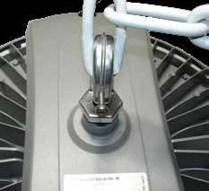
MONTAGEANLEITUNG                                                           INSTALLATION GUIDE

tempLED RayLite Pro Serie                                                  tempLED RayLite Pro series
Allgemeine Sicherheitshinweise                                             General safety notes
                                                             1
Vorsicht!                                                                  Caution!
Gefahr eines elektrischen Schlages!                                        Risk of electric shock!

Montage und Inbetriebnahme der Leuchte nur                                 Mounting and installation of the luminaire only
durch autorisierte Fachkräfte. Vor jeder Arbeit                            by authorized personnel. Disconnect the power
an der Leuchte die Stromzufuhr unterbrechen                                supply and protect it from restarting by mistake
und gegen versehentliches Wiedereinschalten                                before working on the luminaire. The lumin-
sichern. Die Leuchte darf nur mit vollständigem                            aire must only be operated with complete and
und unbeschädigtem Gehäuse in Betrieb genom-                               undamaged housing. Please secure the main
men werden. Die Stromzufuhr ist mit geeigneten                             power by means of suitable measures, for ex-
Maßnahmen (Fehlerstrom-Schutzschalter o.ä.)                                ample a residual current circuit breaker.
abzusichern.

                                                             2
Vorsicht!                                                                  Caution!
Absturzgefahr!                                                             Danger of falling!

Bei der Montage der Leuchte ist darauf zu                                  Please use suitable mounting material (screws,
achten, dass das gewählte Montagematerial                                  wall plugs) and dimensions for the drilling holes
(Schrauben, Dübel) sowie die Dimensionen von                               and screws. They must be suitable for the weight
Bohrlöchern und Schrauben für das Gewicht der                              of the luminaire as well as the composition and
Leuchte und die Beschaffenheit und Tragfähig-                              bearing capacity of the mounting location. No
keit der Montageoberfläche geeignet ist.                                   liability for damages resulting from improper
Keine Haftung für fehlerhaft ausgeführte Monta-                            installation, inexpert operation or modification of
ge, unsachgemäßen Betrieb oder Veränderun-                                 the luminaire!
gen an der Leuchte!

                                                             3
Lieferumfang:                                                                        Package contents:

- Montagehaken mit                                                                   - Mounting hook with
  Sicherungsschraube                                                                   locking screw

                          © tempLED GmbH | Marmorwerkstraße 52 | 83088 Kiefersfelden | Deutschland
                              info@tempLED.de | www.tempLED.de | WEEE-Reg.-Nr.: DE 26163456

                                                         V.01/2020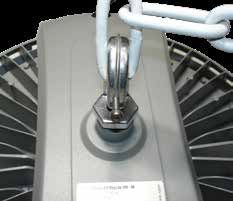
MONTAGEANLEITUNG INSTALLATION GUIDE
tempLED RayLite Pro Serie tempLED RayLite Pro series
Montagehaken Mounting hook
1
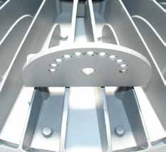
Schritt 1: Step 1:
Montagehaken eindrehen Screw in the mounting hook
Öffnen Sie die Sicherungsschraube am First, open the locking screw of the
Montagehaken. mounting hook.
Drehen Sie den Montagehaken mit Screw the mounting hook with the
dem kompletten Gewinde in die dafür complete thread into the intended
vorgesehene Öffnung auf der Rücksei- opening on the backside of the lumin-
te der Leuchte ein und fest. aire and tighten the mounting hook.
2
Schritt 2: 35 mm Step 2:
Maße des Montagehakens Measurements of the mounting hook
25 mm
DIe genauen Maße des Montage- For detailed dimensions of the mount-
hakens sind in der nebenstehenden 23 mm ing hook, please use the dimension
Maßzeichnung ersichtlich. drawing on the left.
85 mm
40 mm
20 mm
3
Schritt 3: Step 3:
Abhängung einführen Install suspension
Führen Sie nun ihre bauseits vorhan- Introduce your on-site suspension into
dene Abhängung in den Montagehaken the mounting hook.
ein.
(Beispielabbildung hier mit Kettenab- (Symbol picture on the left with chain
hängung) suspension)
© tempLED GmbH | Marmorwerkstraße 52 | 83088 Kiefersfelden | Deutschland
info@tempLED.de | www.tempLED.de | WEEE-Reg.-Nr.: DE 26163456
V.01/2020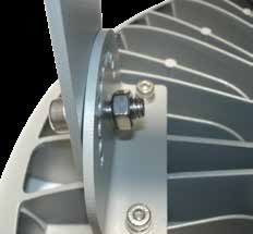
MONTAGEANLEITUNG                                                                      INSTALLATION GUIDE

tempLED RayLite Pro Serie                                                             tempLED RayLite Pro series
Montagehaken                                                                          Mounting hook
                                                              4
Schritt 4:                                                                            Step 4:
Sicherungsschraube schließen                                                          Tighten the locking screw

Drehen Sie die Sicherungsschraube                                                     Close and tighten the locking screw of
des Montagehaken mit einem Inbus-                                                     the mounting hook by using an Allen
schlüssel der Größe 3 komplett ein und                                                key size 3 or a hex wrench size 3.
fest.

(Beispielabbildung hier mit Kettenab-                                                 (Symbol picture on the left with chain
hängung)                                                                              suspension)

                           © tempLED GmbH | Marmorwerkstraße 52 | 83088 Kiefersfelden | Deutschland
                               info@tempLED.de | www.tempLED.de | WEEE-Reg.-Nr.: DE 26163456

                                                          V.01/2020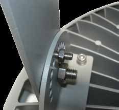
MONTAGEANLEITUNG                                                                      INSTALLATION GUIDE

tempLED RayLite Pro Serie                                                             tempLED RayLite Pro series
Bügelmontage                                                                          Surface mounting
                                                              1
Schritt 1:                                                                            Step 1:
Lieferumfang Montagebügel                                                             Package contents
(Sonderzubehör)                                                                       (additional accessories)
                                                              1
- 1x Montagebügel [1] mit                                                             - 1x Mounting bracket [1] with
  2x Halteplatten [2]                                                                   2x Holder plates [2]
- 2x Halteschrauben mit Mutter [3]                                                    - 2x Holder screws with nut [3]
- 2x Feststellschrauben für die                                                       - 2x Locking screws for
                                                                            4
  Winkelverstellung mit Mutter [4]                                                      angle adjustment with nut [4]
- 4x Montageschrauben [5]                        3                                    - 4x Mounting screws [5]
                                                              5

                                                              2
Schritt 2:                                                                            Step 2:
Montagebügel zerlegen                                                                 Dismantle the holder

Der Montagebügel wird in der Regel                                                    By default, the mounting bracket will
                                                               1
vormontiert geliefert und muss vor                                              4     be delievered pre-installed and has to
der Montage zerlegt werden. Achten                                                    be dismantled before mounting. Please
Sie darauf, keine Beilagscheiben und                                                  be careful not to lose any washers and
Abstandshalter zu verlieren.                                                          spacers.
                                                                        2
Sie brauchen:                                     3                                   You need:
- Inbusschlüssel der Größe 4 und 6                                                    - Allen key / hex wrench size 4 and 6
- Ringschlüssel der Größe 8 und 13                                                    - Ring spanner size 8 and 13

                                                              3
Schritt 3:                                                                            Step 3:
Erste Halteplatte anbringen                                                           Mounting first holder plate

Schrauben Sie die erste Halteplatte [2]                                               Screw the first holder plate [2] of the
des Montagebügels wie auf dem Bild                                                    mounting bracket onto the luminaire as
rechts dargestellt mit den Schrauben                                                  shown on the picture to the left - with
nach aussen mit Hilfe der mitgeliefer-                                                the screws pointing outside. Do so by
ten Montageschrauben [5] und einem                                                    using the included mounting screws
Inbusschlüssel der Größe 4 an der                                                     [5] and an Allen key size 4 or a hex
Leuchte fest.                                                                         wrench size 4.
Vergessen Sie die Abstandshalter
nicht.                                                                                Do not forget the spacers.

                           © tempLED GmbH | Marmorwerkstraße 52 | 83088 Kiefersfelden | Deutschland
                               info@tempLED.de | www.tempLED.de | WEEE-Reg.-Nr.: DE 26163456

                                                          V.01/2020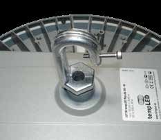
MONTAGEANLEITUNG                                                                                                                       INSTALLATION GUIDE

tempLED RayLite Pro Serie                                                                                                              tempLED RayLite Pro series
Bügelmontage                                                                                                                           Surface mounting
                                                                                   4
Schritt 4:                                                                                                                             Step 4:
Zweite Halteplatte anbringen                                                                                                           Mounting second holder plate

Schrauben Sie die zweite Halteplatte                                                                                                   Screw the second holder plate [2] of
[2] des Montagebügels wie auf dem                                                                                                      the mounting bracket onto the luminaire
Bild rechts dargestellt mit den Schrau-                                                                                                as shown on the picture to the left -
ben nach aussen mit Hilfe der mitge-                                                                                                   with the screws pointing outside. Do so
lieferten Montageschrauben [5] und                                                                                                     by using the included mounting screws
einem Inbusschlüssel der Größe 4 an                                                                                                    [5] and an Allen key size 4 or a hex
der Leuchte fest.                                                                                                                      wrench size 4.
Vergessen Sie die Abstandshalter
nicht.                                                                                                                                 Do not forget the spacers.

                                                                                   5
Schritt 5:                                                                                                                             Step 5:
Anzeichnen der Bohrlöcher                                                                                                              Marking the drill holes
                                                                              160,00 mm

Zeichnen Sie die Bohrlöcher an der                                80,00 mm                   80,00 mm                                  Mark the drill holes on the surface of
Oberfläche des Montageortes an.                                                                                                        the mounting location. Please use the
                                                                                                                            50,00 mm
                                                           10,00 mm

                                                                                                      15,00 mm

Nehmen Sie dazu die nebenstehende                                                                                                      measurement drawing on the left.
Masszeichnung zur Hilfe.
                                                33,00 mm                      23,00 mm                           33,00 mm

Hinweis: die Leuchtenhöhe inkl. Bügel                                         305,00 mm                                                Note: the luminaire height including
beträgt 300 mm.                                                                                                                        bracket is 300 mm.

                                                                                   6
Schritt 6:                                                                                                                             Step 6:
Bohrlöcher anfertigen                                                                                                                  Drilling the holes

Prüfen Sie ggf. die Stellen der Bohrlö-                                                                                                Please check the drilling spots with a
cher mit einem Leitungssuchgerät und                                                                                                   line locator and drill the holes. Choose
fertigen Sie dann die Bohrlöcher an.                                                                                                   a drill hole diameter suitable for the
Wählen Sie einen der Montageober-                                                                                                      material of the mounting surface and
fläche und dem Gewicht der Leuchte                                                                                                     the weight of the luminaire.
angepassten Bohrlochdurchmesser.                                                                                                       (symbol illustration)
(Symbolabbildung)                                                                         Leit
                                                                                             un
                                                                                                 ON
                                                                                                      /O
                                                                                                      FF
                                                                                                g
                                                                                            Lin ssuc
                                                                                               e lo hg
                                                                                                   cat erät
                                                                                                      or

                                                   Driller icon made by Freepik from www.flaticon.com

                            © tempLED GmbH | Marmorwerkstraße 52 | 83088 Kiefersfelden | Deutschland
                               info@tempLED.de | www.tempLED.de | WEEE-Reg.-Nr.: DE 26163456

                                                                             V.01/2020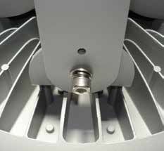
MONTAGEANLEITUNG                                                                      INSTALLATION GUIDE

tempLED RayLite Pro Serie                                                             tempLED RayLite Pro series
Bügelmontage                                                                          Surface mounting
                                                              7
Schritt 7:                                                                            Step 7:
Montieren des Bügels                                                                  Mounting the bracket

Montieren Sie den Bügel mit geeig-                                                    Screw the mounting bracket to the
netem Schraubenmaterial für die Mon-                                                  surface. Use screw material suitable for
tageoberfläche und dem Gewicht der                                                    the mounting surface and the weight
Leuchte. Wir empfehlen den Einsatz                                                    of the luminaire. We recommend
von Edelstahlschrauben.                                                               high-grade steel screws and mounting
(Symbolabbildung)                                                                     material.
                                                                                      (symbol illustration)

                                                              8
Schritt 8:                                                                            Step 8:
Montieren der Leuchte 1                                                               Mounting the luminaire 1

Montieren Sie die Leuchte an den                                                      Mount the luminaire on the bracket by
Montagebügel und setzen Sie dazu die                                                  inserting the two holder screws half
beiden Halteschrauben [3] zur Hälfte                                                  way [3] .
ein.

Vergessen Sie die Abstandshalter und                                                  Do not forget the spacers and washers.
Beilagscheiben nicht.

                                                              9
Schritt 9:                                                                            Step 9:
Montieren der Leuchte 2                                                               Mounting the luminaire 2

Setzen Sie jeweils die passende Mutter                                                Put the suitable nut onto each holder
auf die Halteschrauben auf und ziehen                                                 screw and tighten both by using an
Sie beides mit Hilfe eines Inbusschlüs-                                               Allen key size 6 or a hex wrench size 6
sels der Größe 6 und eines Ringschlüs-                                                and a ring spanner size 13.
sels der Größe 13 fest.

Wir empfehlen ein Drehmoment von                                                      We recommend a maximum torque of
maximal 7,5 Nm.                                                                       7.5 Nm.

                           © tempLED GmbH | Marmorwerkstraße 52 | 83088 Kiefersfelden | Deutschland
                              info@tempLED.de | www.tempLED.de | WEEE-Reg.-Nr.: DE 26163456

                                                          V.01/2020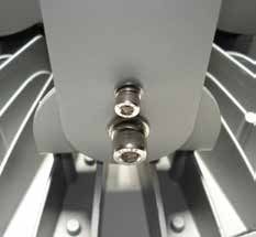
MONTAGEANLEITUNG                                                                     INSTALLATION GUIDE

tempLED RayLite Pro Serie                                                            tempLED RayLite Pro series
Bügelmontage                                                                         Surface mounting
                                                            10
Schritt 10:                                                                          Step 10:
Winkel einstellen 1                                                                  Angle adjusting 1

Stellen Sie den gewünschten Winkel                                                   Adjust the luminaire angle according to
ein und setzen Sie anschließend die                                                  your specific needs and put in the two
beiden Feststellschrauben [4] der Win-                                               locking screws [4] of the angle adjust-
kelverstellung zur Hälfte ein.                                                       ment half way.

                                                            11
Schritt 11:                                                                          Step 11:
Winkel einstellen 2                                                                  Angle adjusting 2

Setzen Sie jeweils die passende Mutter                                               Put the suitable nut onto each locking
auf die Feststellschrauben der Winkel-                                               screw of the angle adjustment and
verstellung auf und ziehen Sie beides                                                tighten both by using an Allen key size
mit Hilfe eines Inbusschlüssels der                                                  4 or a hex wrench size 4 and a ring
Größe 4 und eines Ringschlüssels der                                                 spanner size 8.
Größe 8 fest.

                          © tempLED GmbH | Marmorwerkstraße 52 | 83088 Kiefersfelden | Deutschland
                              info@tempLED.de | www.tempLED.de | WEEE-Reg.-Nr.: DE 26163456

                                                         V.01/2020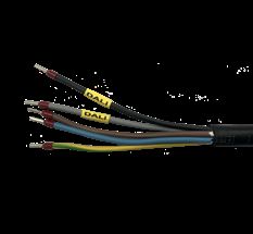
MONTAGEANLEITUNG                                                            INSTALLATION GUIDE

tempLED RayLite Pro Serie                                                   tempLED RayLite Pro series
Elektrische Anschlüsse                                                      Electrical power connections
                                                              1
Schritt 1: Vorsicht!                                                        Step 1: Caution!
Gefahr eines elektrischen Schlages!                                         Risk of electric shock!

Montage und Inbetriebnahme der Leuchte nur                                  Mounting and installation of the luminaire only
durch autorisierte Fachkräfte. Vor jeder Arbeit                             by authorized personnel. Disconnect the power
an der Leuchte die Stromzufuhr unterbrechen                                 supply and protect it from restarting by mistake
und gegen versehentliches Wiedereinschalten                                 before working on the luminaire.
sichern.

                                                              2
Schritt 2:                                                                            Step 2:
Kombikabel                                                                            Combined cable

Die tempLED RayLite Pro Serie ver-                                                    The tempLED RayLite Pro series uses
wendet ein Kombikabel sowohl für den                                                  a combined cable for electrical con-
Netz- als auch für den DALI-Anschluß.                                                 nection and for DALI-connection. For
Die Adernbelegung ist in Schritt 3                                                    wiring, please check step 3.
dargestellt.

Isolieren Sie nicht verwendete Adern                                                  Do not forget to isolate all unused wires
fachgerecht gegen Kurzschluss.                                                        professionally to prevent short circuits.

                                                              3
Schritt 3:                                                                            Step 3:
Adernbelegung                                                                         Wiring

Die Adernbelegung des Kombikabels                                         L           The wiring of the power cable is as
lautet wie folgt:                                                                     follows:

Phase [L] - braun                                                      N              Power conductor [L] - brown
Schutzleiter (Erdung) - gelb/grün                                     DALI            Protective conductor - yellow/green
Neutralleiter [N] - blau                                                              Neutral conductor [N] - blue
DALI - grau                                                           DALI            DALI - grey
DALI - violett                                                                        DALI - purple

                           © tempLED GmbH | Marmorwerkstraße 52 | 83088 Kiefersfelden | Deutschland
                               info@tempLED.de | www.tempLED.de | WEEE-Reg.-Nr.: DE 26163456

                                                          V.01/2020
MONTAGEANLEITUNG INSTALLATION GUIDE
tempLED RayLite Pro Serie tempLED RayLite Pro series
Anhang Appendix
Technische Basisdaten: Basic technical data:
Spannungsversorgung 100 - 240 V~ / 50 - 60 Hz Power input
Maximaler Einschaltstrom 75 A Maximum inrush current
Schutzart IP65 Protection class
Produkthöhe 205 mm Height of the luminaire
Produkthöhe mit Montagebügel 300 mm Height with bracket included
Produktdurchmesser 420 mm Diameter of the luminaire
Maximales Produktgewicht 7000 g Maximum weight of the luminaire
Montagezubehör: Mounting accessories:
Montagebügel 932152 Luminaire holder
Montagebügel Edelstahl 932154 Luminaire holder stainless steel
Masthalter für Mastaufsatz 932165 Pole mounting set
Halterohr für Stabmontage 1,00m 932162 Support tube 1,00m for rod assembly
Halterohr für Stabmontage 1,50m 932163 Support tube 1,50m for rod assembly
Halterohr für Stabmontage 2,00m 932164 Support tube 2,00m for rod assembly
Kran-Montage-Kit 932810 Crane mounting set
Wandbügel Edelstahl 934042 Wall bracket stainless steel
Technische Änderungen vorbehalten. Specifications are subject to change
without notice.
© tempLED GmbH | Marmorwerkstraße 52 | 83088 Kiefersfelden | Deutschland
info@tempLED.de | www.tempLED.de | WEEE-Reg.-Nr.: DE 26163456
V.01/2020Sie können auch lesen