Einbauanleitung Abgasklappensystem für KIA Stinger Modelle - Bastuck
←
→
Transkription von Seiteninhalten
Wenn Ihr Browser die Seite nicht korrekt rendert, bitte, lesen Sie den Inhalt der Seite unten
Abgasklappensystem
für KIA Stinger Modelle

  Einbauanleitung

                      Stand: 18.04.2019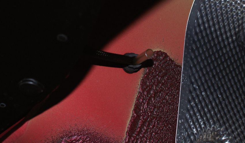
1)   Entfernen der
     Armaturenbrettverkleidung
     und Ausbau des Kombiinstrument

a)   Entfernen Sie die seitliche
     Armaturenbrettabdeckung mit Hilfe
     eines Ausbauwerkzeuges

                                            101

b)   Lösen Sie die Schrauben (3) und
     entfernen Sie die untere
     Armaturenbrettverkleidung.

                                            102

c)   Ziehen Sie den Steckverbinder ab
     und legen Sie die untere
     Armaturenbrettverkleidung zur Seite.

                                            103

                                                  Stand: 18.04.2019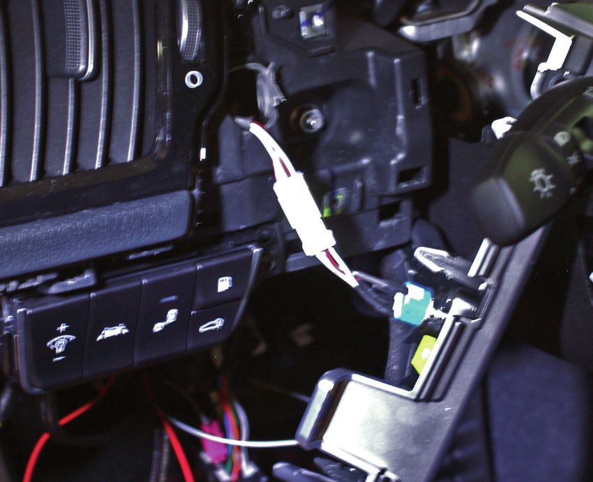
d)   Lösen Sie die Schraube (1) und
     entfernen Sie das Ziergitter.

                                              104

e)   Lösen Sie die Schrauben (3) und
     entfernen Sie die
     Armaturenbrettverkleidung auf der
     Fahrerseite.

                                             105

f)   Entfernen Sie die seitliche
     Armaturenbrettabdeckung auf der
     rechten Seite (Beifahrerseite) mit
     Hilfe eines Ausbauwerkzeuges

                                             106

                                                    Stand: 18.04.2019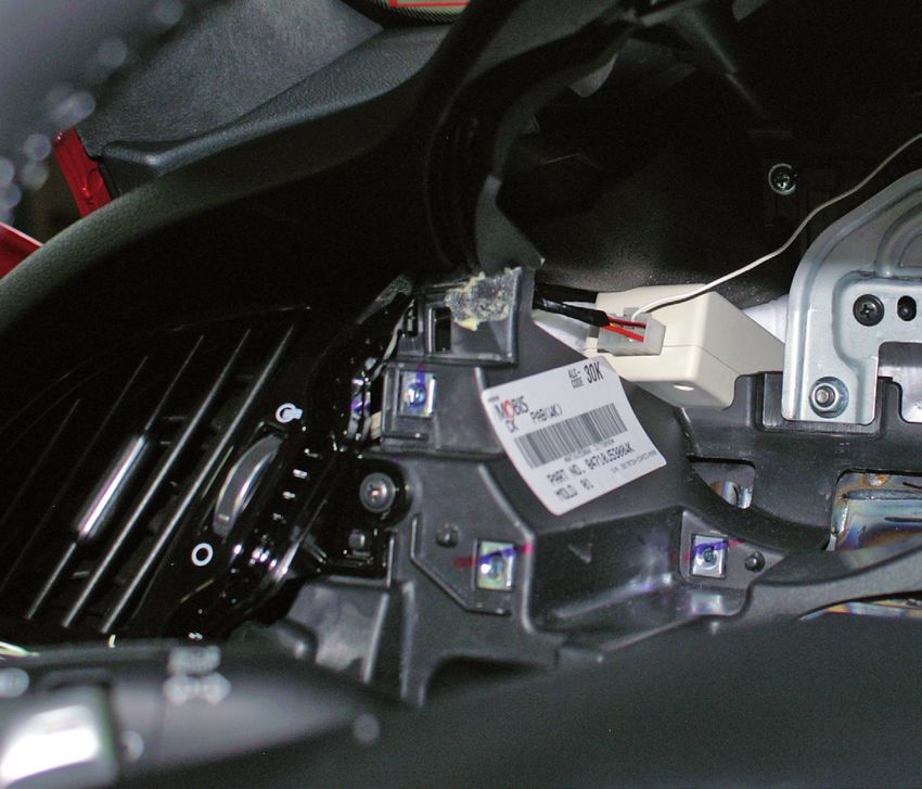
g)   Lösen Sie die
     Befestigungsschraube (1) und lösen
     Sie die Armaturenbrettzierleiste.

                                            107

h)   Lösen Sie die Schrauben (4) und
     lösen Sie die mittlere
     Armaturenbrettverkleidung.

                                            108

i)   Ziehen Sie den Steckverbinder des
     Startknopfes ab und legen Sie die
     Armaturenbrettverkleidung zur Seite.

                                            109

                                                  Stand: 18.04.2019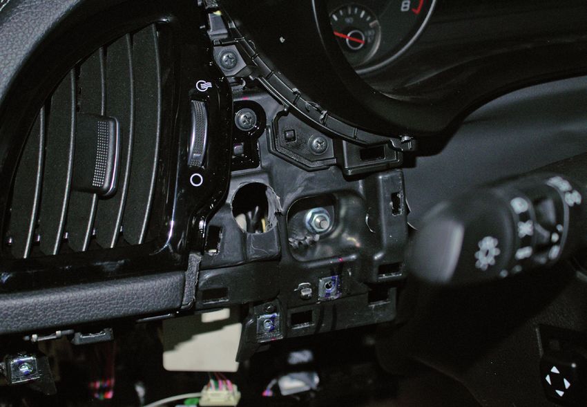
j)   Lösen Sie die Schrauben (4) und
     entfernen Sie mit Hilfe eines
     Ausbauwerkzeuges die Lenksäulen-
     und Tachoabdeckung.

                                          110

k)   Lösen Sie die Schrauben (4) und
     ziehen Sie das Kombiinstrument
     nach vorne. Lösen Sie anschließend
     die Steckverbindung und entfernen
     Sie das Kombiinstrumen.

                                          111

                                          112

                                                Stand: 18.04.2019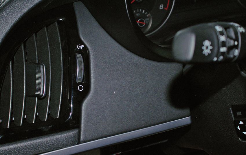
2)   Ausbau des Kombiinstrument

a)   Lösen Sie die Schrauben (3)
     und ziehen Sie das Kombiinstrument
     nach vorne heraus.

                                          113

b)   Lösen Sie den Steckverbinder am
     Kombiinstrument.

                                          114

3)   Innenverkleidung im Kofferraum
     und hintere Sitzbank ausbauen

a)   Heben Sie den Kofferraumboden,
     die Ablage, sowie die Hutablage
     heraus.

                                          115

                                          116

                                                Stand: 18.04.2019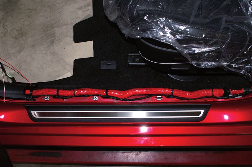
b)   Lösen Sie die beiden
     Kunststoffschrauben und entfernen
     Sie die Querverblendung.

                                            117

c)   Lösen Sie die beiden
     Befestigungsschrauben der
     Rücksitzbank.

                                            118

d)   Ziehen Sie ggf. die Steckverbindung
     der Sitzheizung ab und entfernen
     Sie die Sitzbank.

                                            119

e)   Lösen Sie die Schraube (1) der
     linken Seitenverkleidung und
     entfernen Sie diese.

                                                  120

f)   Lösen Sie die Schrauben (3) der
     linken Gepäckraumseitenverkleidung
     und entfernen Sie diese.

                                           121
                                                        Stand: 18.04.2019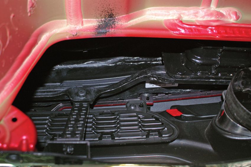
4)   Türeinstiegsverkleidungen
     entfernen

a)   Mit Hilfe eines Schraubendrehers
     oder eines Abziehers entfernen Sie
     vordere Türeinstiegsverkleidung.

                                            122

b)   Mit einem Abziehers entfernen Sie
     die hintere Türeinstiegsverkleidung.

                                            123

c)   Lösen Sie den unteren Teil der
     B-Säulenverkleidung

                                            124

                                                  Stand: 18.04.2019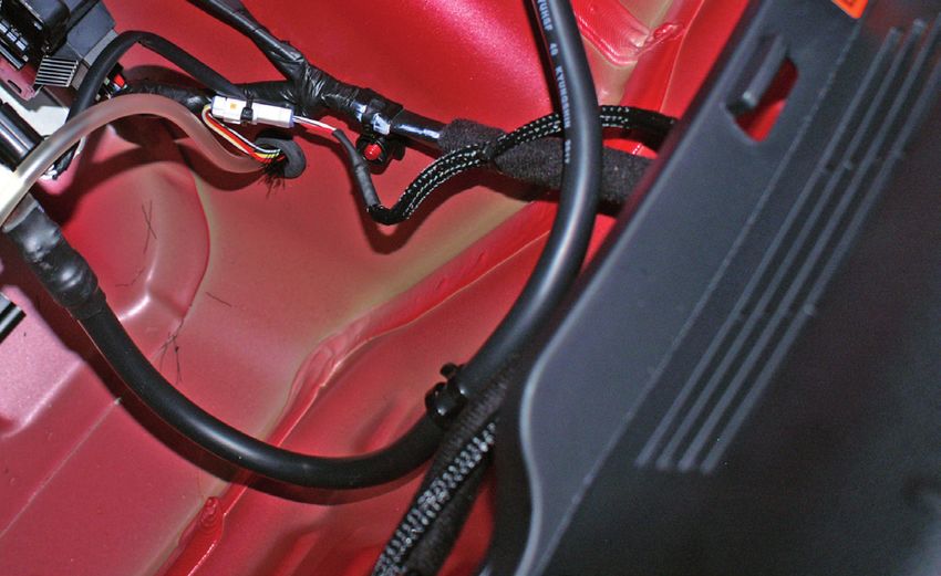
5)   Verlegung des Kabelstrangs                Rechts
     im Außenbereich

a)   Der Kabelstrang besteht aus
     zwei Teilen. Verlegen Sie zuerst den
     kürzeren Teil mit den Stecker für die
     beiden Abgasklappen (Y-Kabel).

     Verlegen Sie das Kabel entlang
     des Kabelstrangs der
     Parksensoren innerhalb der 		             125
     Heckstoßstange, oberhalb der
     Crashstruktur und fixieren Sie die        Links
     Kabel mit Kabelbinder.

                             Sicherungsstift
                             verriegeln!

      126

                                               127

b)   Lösen Sie den Schlauch der
     Batterieentlüftung aus der originalen
     Gummitülle und führen Sie den
     Kabelstrang gemeinsam mit
     dem Schlauch der Batterientlüftung
     durch die neue, beigelegte
     Gummitülle in das Fahrzeug.

     Stellen Sie sicher, dass die
     Durchführung von Kabelstrang
                                               128
     und Schlauch nach Abschluss
     der Arbeiten wieder sicher
     vor Staub und Spritzwasser
     abdichtet!

                                               129

                                                        Stand: 18.04.2019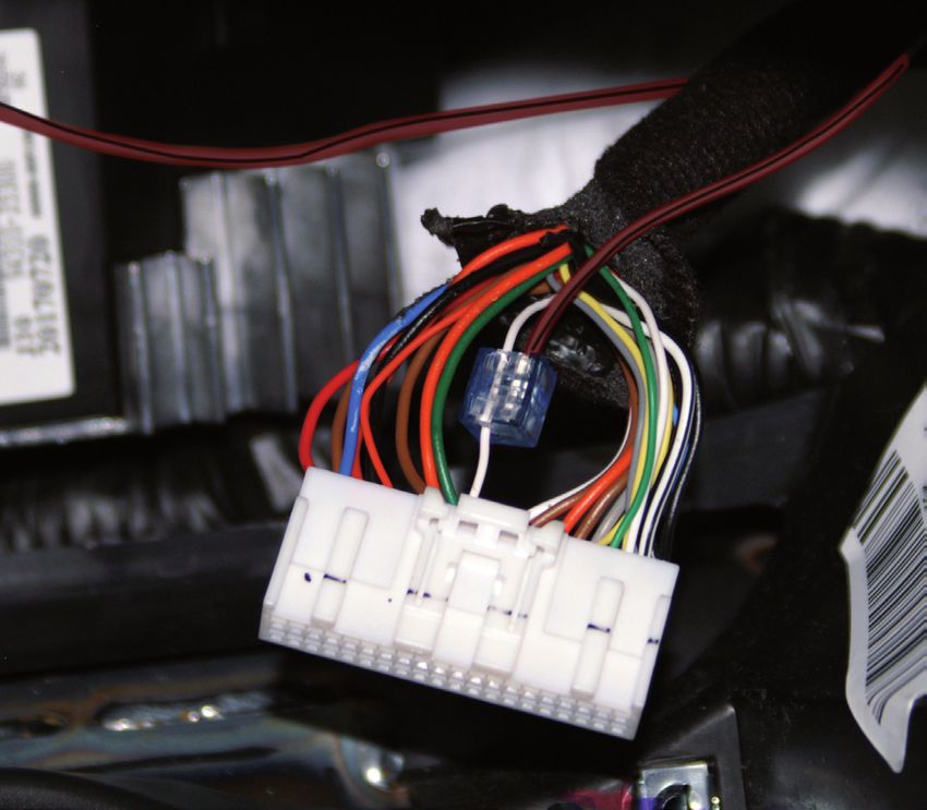
6)     Verlegen des Kabelstrangs
       im Innenbereich

a)     Verlegen Sie den Hauptkabelstrang
       ausgehend von der Trennstelle
       im Kofferraum bis nach
       vorne zum Sicherungskasten /
       Kombiinstrument.
       Folgen Sie immer dem original
                                                   130
       Fahrzeugkabelstrang entlang
       des Schwellers und fixieren Sie das
       Kabel mit ausreichend Kabelbinder.

                                                   131

                                             133

 132

                                                         Stand: 18.04.2019
b) Verlegen Sie den Kabelstrang entlang
des original Kabelbaum von hinten bis
in den Sicherungskasten.
Führen Sie von dort aus den
Stecker zum Anschluss des
Steuergeräts innerhalb des
Armaturenbretts, vorbei
am Lüftungsschacht bis in den
Freiraum des Multiinstrumentes.
c) Das Signalkabel zum Abgriff des
Tachosignal verlegen Sie hinter
dem Metallträger bis zum Stecker
des Multifunktionsinstruments. 134
135
7) Elektrischer Anschluss
a) Anschluss der Minusleitung
(schwarz/weiß) an die
Fahrzeugmasse.
Abgriff: Data Link Connector 136
Pin 5 (schwarz)
Ansicht Rückseite! View of the back!
Stand: 18.04.2019b) Anschluss der Signalleitung
(rot/schwarz) für das
Geschwindigkeitssignal.
Abgriff: Kombiinstrument
Pin 12 (weiß)
137
Ansicht Rückseite! View of the back!
138
c) Anschluss der 12V
Versorgungsspannung
(rot)
Abgriff: Stecker I/P-C
Sicherungskasten KL15
Pin 21 (weiß)
Ansicht Rückseite!
View of the back!
139
140
Hinweis:
Der Abgriff der Signale kann durch die Verwendung von „Stromdieben“ erfolgen. Bitte
nutzen Sie in diesem Fall nur die beigelegten Teile oder stellen Sie vor der Verwendung
eigener Kabelverbinder sicher, dass diese für einen Kabelquerschnitt von 0,5 mm² für
Masse und KL15 sowie 0,25 mm² für den Abgriff des Tachosignals ausgelegt sind!
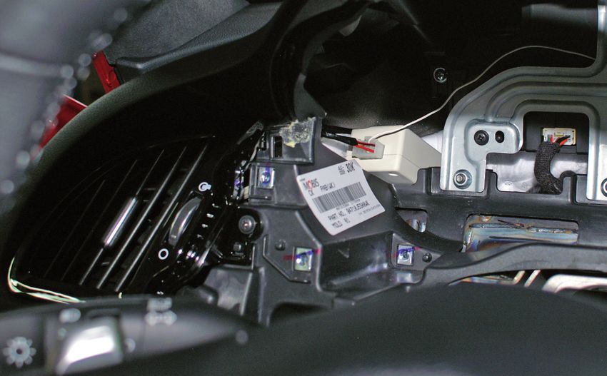
Stand: 18.04.20198) Einbau des Steuergeräts
a) Das Steuergerät wird auf der linken
Seite hinter dem Kombiinstrument
verbaut.
Fixieren Sie das Gerät dort mit
Kabelbinder oder Duallock so dass es
sich nicht lösen kann.
Nutzen Sie den beigelegten
Schaumstoff um das Gerät zu
entkoppeln und Vibrationsgeräuschen
vorzubeugen.
141
9) Einbau des Schalters zur
Aktivierung
a) Nutzen Sie die beigefügte
Bohrschablone!
Schneiden Sie diese aus und
überprüfen Sie anhand der
aufgedruckten Skala den Maßstab!
b) Legen Sie die Bohrschablone auf die
Armaturenbrettverkleidung.
Zeichnen Sie das Bohrloch an.
142
c) Clipsen Sie die
Armaturenbrettverkleidung wieder in
das Armaturenbrett und bohren Sie
mit einem Bohrer Ø 5,0 mm ein
Loch durch die Verkleidung und durch
das Armaturenbrett dahinter.
Ein Staubsauger hilft das Fahrzeug
frei von Bohrspänen zu halten.
143
144
Stand: 18.04.2019d) Entfernen Sie die Verkleidung wieder
und weiten Sie mit Hilfe eines
Stufenbohrer erst das Loch im
Armaturenbrett und anschließend das
Loch im Verkleidungsteil auf Ø20,0mm.
Montieren Sie den Schalter in das
Loch der Armaturenbrettverkleidung.
145
146
10) Zusammenbau
Der Zusammenbau der Innenverkleidung und das Einsetzen des Kombiinstrumentes
geschieht in umgekehrter Reihenfolge des Ausbaus. Bitte dazu auch die
Kapitel im Werkstatthandbuch beachten.
Nach dem Einbau der
Armaturenbrettverkleidung mit dem
Schalter zur Aktivierung der
Klappensteuerung verbinden Sie bitte
das Kabel des Schalter mit dem
Kabelstrang des Abgasklappensystem
und fahren erst danach mit dem weiteren
zusammenbau des Armaturenbrett fort.
147
Zu lange Kabel sind eventuell zu kürzen oder mit Kabelbinder hochzubinden, damit
keine Reibung entsteht und sie nirgends stören.
Stand: 18.04.201911) Test des System
a) Schließen Sie die Batterie wieder an und schalten Sie die Zündung ein.
Die Abgasklappe öffnet und schließt einmal.
Durch einmaliges Drücken auf den Schalter wird das System aktiviert. Der Schalter leuchtet
jetzt blau.
b) Starten Sie zu einer Probefahrt und prüfen Sie, ob das System ordnungsgemäß
arbeitet und alle Teile korrekt fixiert sind.
Stand: 18.04.2019Exhaust flap system
for KIA Stinger models
Assembly instructions
1) Removal of the dashboard cladding and disassembly of the combination instrument
(see figures 101-112)
a) Remove the lateral dashboard cladding by using a removal tool.
b) Loosen the screws (3) and remove the dashboard cladding on the bottom side.
c) Unplug the connector and put aside the dashboard cladding of the bottom side.
d) Loosen the screw (1) and remove the ornamental grille.
e) Loosen the screws (3) and remove the dashboard cladding on the driver’s side.
f) Disassemble the lateral dashboard cladding on the right side (passenger’s side) by using a
removal tool.
g) Loosen the mounting screw (1) and remove the dashboard moulding.
h) Loosen the screws (4) and remove the central dashboard cladding.
i) Unplug the connector of the start button and put aside the dashboard cladding.
j) Loosen the screws (4) and disassemble the cladding of the steering column and the
speedometer cladding by using a removal tool.
k) Loosen the screws (4) and pull the combination instrument forward. Then loosen the
connector and remove the combination instrument.
2) Disassembly of the combination instrument
(see figures 113-114)
a) Loosen the screws (3) and pull out the combination instrument forwards.
b) Unplug the connector at the combination instrument.
3) Disassemble the interior trunk cladding and remove the back seats
(see figures 115-121)
a) Take out of your car the trunk floor, the shelf, as well as the hat rack.
b) Loosen the two plastic screws and remove the rear panel cladding.
c) Loosen both mounting screws of the back seats.
d) If the car has a seat heating, unplug the connector of the seat heating and disassemble the
rear seats.
e) Loosen the screws (1) of the left side cladding and remove them.
f) Loosen the screws (3) of the trunk cladding on the left and remove them.
Stand: 18.04.20194) Remove the cladding of the door entrance area
(see figures 122-124)
a) Remove the cladding of the front door entrance area by using a screwdriver or another
appropriate tool.
b) Remove the cladding of the rear door entrance area with a removal tool.
c) Remove the lower part of the B-column cladding.
5) Laying the cables of the wiring harness outside the car inside the bumper
(see figures 125-129)
a) The wiring harness consists of two parts. First, lay the shorter part of the wiring harness
with the plugs for the two exhaust flaps (Y-cable).
Then lay the cable alongside the cable section of the parking sensors inside the rear
bumper, above the crash structure and fix the cables with cable ties.
Latch the locking pin! (see figure 126)
b) Undo the hose of the battery vent from the original rubber grommet and feed the wiring
harness as well as the hose of the battery vent through the new rubber grommet provided
into the vehicle.
Make sure the grommet of the wiring harness and the hose seal properly against dust
and splashing water again once the work has been completed!
6) Lay the cables of the wiring harness in the interior
(see figures 130-135)
a) Lay the main wiring harness beginning at the junction point in the trunk to the fuse box /
combination instrument in the car’s front section. Always follow the original wiring harness of
the vehicle alongside the door sill and fix the cable with a sufficient number of cable ties.
b) Lay the wiring harness alongside the original wiring harness starting at the back of the car
until arriving at the fuse box. Feed the plug from this point to the connection of the control
unit inside the dashboard, passing by the ventilation shaft until you get to the free space of
the multi-instrument.
c) Lay the signal wire to pick off the speedometer signal behind the metal carrier up to the plug
of the multi-function instrument.
7) Electrical connection
(see figures 136-140)
a) Connect the negative wire (black/white) to ground.
Pick-off: Data Link Connector
pin 5 (black) (see figure 136)
b) Connection of the signal cable (red/black) for the speed signal.
Pick-off: combination instrument
pin 12 (white) (see figures 137-138)
c) Connectin of the 12V supply voltage (red)
Pick-off: Plug I/P-C
fuse box KL15
pin 21 (white) (see figures 139-140)
Stand: 18.04.2019Note:
The pick-off of the signals can be implemented by the use of snap-lock connectors.
Please only use the parts provided in this case or make sure the cable connectors
are designed for a cable cross section of 0.5 mm² for ground and terminal 15 as well
as 0.25 mm² for the pick-off of the speedometer signal before using your own cable
connectors!
8) Installation of the control unit
(see figure 141)
a) The control unit is to be installed on the left side behind the combination instrument. Fix the
control unit with cable ties or Duallock so it cannot come loose. Use the provided foam to
remove the unit in order to decouple it and to prevent it from causing vibration noise.
9) Installation of the activation switch
(see figures 142-146)
a) Please use the drill template on the last page of this instruction! Cut out the drill template
and check the scale by using the imprinted one at the back!
b) Put the drill template on the dashboard cladding. Mark the position of the borehole.
c) Attach the dashboard cladding to the dashboard and drill a hole of Ø 5.0 mm into the
cladding as well as the dashboard behind it by using a drilling machine. A vacuum cleaner
will help you to keep your vehicle free from drilling chips.
d) Remove the cladding again and widen the borehole to Ø 20.0 mm with the help of a step
drill, first in the dashboard itself and afterwards the hole in the cladding. Install the switch
where the hole in the dashboard cladding has been drilled.
10) Reassembly
(see figure 147)
The interior cladding and the combination instrument have to be reassembled in the reverse
order as the removal. Please also read the relevant chapters in the workshop manual.
After having reassembled the dashboard cladding with the switch to activate the valve
control connect the cable of the switch to the wiring harness of the exhaust flap system.
Please continue with the further reassembly of the dashboard only after this.
Long cables might have to be shortened correspondingly or are to be attached using cable
ties to avoid friction and that they might hinder.
11) Testing the system
a) Reconnect the battery and switch on the ignition. The exhaust flap will open and close once.
By pressing the switch you will activate the system. The switch lights up blue.
b) Now make a test drive and check if the system is functioning properly and if all parts are
correctly fixed.
Stand: 18.04.2019Stand: 18.04.2019
Système de clapet
                             d’échappement pour les
                               modèles KIA Stinger
                          Instructions de montage
1)   Enlever l’habillage du tableau de bord et démonter le combiné d’instruments
     (voir fig. 101-112)

a)   Enlever l’habillage latérale du tableau de bord en utilisant un outil de dépose.
b)   Desserrer les vis (3) et enlever l’habillage inférieur du tableau de bord.
c)   Débrancher le connecteur et mettre de côté l’habillage inférieur du tableau de bord.
d)   Desserrer la vis (1) etenlever la grille décorative.
e)   Desserrer les vis (3) et enlever l’habillage du bord de tableau sur le côté conducteur.
f)   Enlever l’habillage latérale du tableau de bord sur le côté droit (côté passager) en utilisant
     un outil de dépose
g)   Desserrer la vis de fixation (1) et enlever la baguette du tableau de bord.
h)   Desserrer les vis (4) et enlever l’habillage central du tableau de bord.
i)   Débrancher le connecteur du bouton de démarrage et mettre de côté l’habillage du tableau
     de bord.
j)   Desserrer les vis (4) et enlever l’habillage de la colonne de direction et du compteur en
     utilisant un outil de dépose
k)   Desserrer les vis (4) et tirer vers l’avant le combiné d’instruments. Ensuite débrancher le
     connecteur et enlever le combiné d’instruments.

2)   Démontage du combiné d’instruments
     (voir fig. 113-114)

a)   Desserrer les vis (3) et enlever le combiné d’instruments vers l’avant.
b)   Débrancher le connecteur sur le combiné d’instruments.

3)   Démonter le revêtement intérieur dans le coffre et la banquette arrière
     (voir fig. 115-121)
a)   Retirer le plancher du coffre, le fond de coffre ainsi que la plage arrière.
b)   Desserrer les deux vis en plastique et enlever le revêtement transversal à l’intérieur du
     coffre.
c)   Desserrer les deux vis de fixation de la banquette.
d)   Débrancher le connecteur des sièges chauffants et enlever la banquette si nécessaire.
e)   Desserrer la vis (1) du revêtement latéral gauche et les enlever.
f)   Desserrer les vis (3) du panneau latéral gauche du coffre et l’enlever.

                                                                                    Stand: 18.04.2019
4) Enlever le revêtement de seuil de porte
(voir fig. 122-124)
a) En utilisant un tournevisou un autre outil adéquat enlever le revêtement de seuil de porte
avant.
b) Un utilisant l’outil adéquat enlever le revêtement de seuil de porte arrière.
c) Desserrer la partie inférieure du revêtement du montant B.
5) Pose du faisceau de câbles dans la zone extérieure
(voir fig. 125-129)
a) Le faisceau de câbles se compose de deux parties. Premièrement, poser la partie courte
avec les connecteurs pour les clapets d’échappement (câble Y).
Poser le câble le long du faisceau de câbles des capteurs de stationnement dans l’intérieur
du pare-chocs arrière, au dessus de la structure « crash management » et fixer les câbles
avec les colliers de câble.
Verrouiller la goupille de sécurité! (see figure 126)
b) Enlever le tuyau du dégazage de la batterie du passe-fil en caoutchouc d’origine et poser
le faisceau de câbles ainsi que le tuyau du dégazage de la batterie par le nouveau passe-fil
en caoutchouc fourni vers l’intérieur du véhicule.
Veuillez vérifier que le passe-fil du faisceau de câbles et du tuyau est étanche contre
la poussière et les projections d’eau une fois les travaux terminés!
6) Pose du faisceau de câbles dans l’intérieur
(voir fig. 130-135)
a) Poser le faisceau de câbles principal en commençant avec le point de séparation électrique
dans le coffre vers l’avant jusqu’au boîtier de fusibles / combiné d’instruments. Veuillez
toujours suivre le faisceau de câbles d’origine le long du seuil et fixer le câble en utilisant
suffisant d’attaches-câbles.
b) Poser le faisceau de câbles le long du faisceau de câbles d’origine de l’arrière jusqu’au
boîtier de fusible. De là, faire passer le connecteur du branchement de l’appareil de
commande placé dans l’intérieur du tableau de bord, en passant par les puits d‘aération
jusqu’à l’espace vide de l’instrument multifonction.
c) Poser le câble des signaux pour capter le signal tachymétrique derrière le support
métallique jusqu’au connecteur à l’instrument multifonction.
7) Raccordement électrique
(voir fig. 136-140)
a) Raccordement du câble négatif (noir/blanc) à la masse.
Prise de prélèvement: connecteur de liaison de transmission de données de véhicule (DLC)
Goupille 5 (noir) (voir fig. 136)
b) Raccordement du câble des signaux (rouge/noir) pour le signal de vitesse.
Prise de prélèvement: combiné d’instruments
Goupille 12 (blanc) (voir fig. 137-138)
c) Raccordement de la tension d’alimentation 12V (rouge)
Prise de prélèvement: connecteur I/P-C
Boîtier de fusibles KL15
Goupille 21 (blanc) (voir fig. 139-140)
Stand: 18.04.2019Remarque:
La prise des signaux peut être réalisée par des répartiteurs. Dans ce cas, veuillez
utiliser exclusivement les pièces fournies ou assurez-vous avant l’utilisation de vos
propres connecteurs de câble que ces connecteurs sont conçus pour une section
transversale du câble de 0,5 mm² pour masse et borne 15 ainsi que 0,25 mm² pour la
prise du signal tachymétrique!
8) Installation de l’appareil de commande
(voir fig. 141)
a) L’appareil de commande s’installe à gauche derrière le combiné d’instruments.Fixer
l’appareil là en utilisant des attaches de câble ou bande de fixation duallock afin que
l’appareil ne puisse pas se desserrer.Utiliser la mousse plastique fournie pour découpler
l’appareil et pour prévenir d’éventuel bruit de vibration.
9) Installation de l’interrupteur d’activation
(voir fig. 142-146)
a) Utiliser le gabarit de perçage ci-joint! Couper-le et contrôler l’échelle en le comparant avec
l’échelle imprimée!
b) Mettre le gabarit de perçage au revêtement du tableau de bord. Marquer le trou de perçage.
c) Fixer à nouveau l’habillage du tableau de bord au tableau de bord et percer avec une
perceuse Ø 5,0 mm un trou dans l’habillage et dans le tableau de bord derrière. Utilisant un
aspirateur, le véhicule reste exempt de copeaux de perçage.
d) Enlever l’habillage de nouveau et premièrement élargir le trou dans le tableau de bord
à l’aide d’un foret étagé et ensuite élargir le trou dans l’habillage à Ø20,0 mm. Installer
l’interrupteur dans le trou dans le tableau de bord.
10) Assemblage
(voir fig. 147)
L’assemblage de l’habillage intérieur et l’assemblage du combiné d’instruments s’effectue
dans l’ordre inverse du démontage. Veuillez respecter aussi les chapitres correspondants
dans le manuel.
Après avoir assemblé l’habillage du tableau de bord comprenant l’interrupteur d’activation
de la commande de clapet, connecter le câble de l’interrupteur au faisceau de câbles du
système d’échappement. Ensuite continuer à assembler le tableau de bord.
Il est possible qu’il faut raccourcir des câbles trop longues ou de les attacher en utilisant
des attaches câble, afin d’éviter tous frottements et afin qu’ils ne perturbent pas en aucun
point.
11) Testing the system
a) Raccorder de nouveau la batterie et activer l’allumage. Le clapet d’échappement s’ouvre et
ferme une fois. En appuyant sur l’interrupteur une fois le système s’active. L’interrupteur est
allumé en bleu.
b) Faire un parcour d’essai afin de contrôler le bon fonctionnement du système et pour tester
si toutes pièces sont fixés correctement.
Stand: 18.04.2019Stand: 18.04.2019
Stand: 18.04.2019
Conexión del cable negativo (negro/blanco) a la masa del vehículo
Toma: Data Link Connector
Pin 5 (negro) (véase fig. 136)

Conexión del cable de señal (rojo/negro) para el señal de velocidad.

                                                                       Stand: 18.04.2019
Stand: 18.04.2019
Stand: 18.04.2019
20

     5

                        Bohschablone
                        KIA Stinger
                        V.1.0

30
                   42

                                                     25

                                Prüfe den Maßstab!
                                check the scale!

                                        25

          100 mm

                                        Stand: 18.04.2019
Sie können auch lesen