MONTAGEHINWEIS INSTALLATION INSTRUCTIONS - Easy Clean Hatz Diesel
←
→
Transkription von Seiteninhalten
Wenn Ihr Browser die Seite nicht korrekt rendert, bitte, lesen Sie den Inhalt der Seite unten
CREATING POWER SOLUTIONS.

 Easy Clean²

 MONTAGEHINWEIS
 INSTALLATION INSTRUCTIONS

 Hatz Diesel

 www.hatz-diesel.com
Inhaltsverzeichnis / Table of Contents

deutsch.......................................................................................................     2

english.........................................................................................................   21
Inhaltsverzeichnis                                                                                                                                                 Easy Clean²

Inhaltsverzeichnis

1                    Impressum.................................................................................................................................................. 3

2                    Sicherheit ................................................................................................................................................... 4
2.1                  Gerätespezifische Sicherheitshinweise.......................................................................................................................... 4

3                    Montageanleitung ...................................................................................................................................... 5
3.1                  Demontage Dieselpartikelfilter chassisfest 12V / 24V.................................................................................................... 5
3.2                  Montage Dieselpartikelfilter chassisfest 12V / 24V ........................................................................................................ 9
3.3                  Demontage Dieselpartikelfilter motorfest 12V / 24V..................................................................................................... 13
3.4                  Montage Dieselpartikelfilter motorfest 12V / 24V ......................................................................................................... 16

2                                                                                                                                                                          HATZ
Easy Clean²                                                                                             Impressum

1       Impressum
        Kontaktdaten
              © 2021
              Motorenfabrik HATZ
              Ernst-Hatz-Straße 16
              94099 Ruhstorf
              Deutschland
              Tel. +49 (0)8531 319-0
              Fax +49 (0)8531 319-418
              marketing@hatz-diesel.de
              www.hatz-diesel.com
              Alle Rechte vorbehalten!

        Copyright
              Das Copyright für diese Anleitung liegt ausschließlich bei Motorenfabrik HATZ, Ruhstorf.
              Die vorliegende Anleitung darf nur mit schriftlicher Genehmigung vervielfältigt oder an Dritte weiter-
              gegeben werden. Dies trifft auch dann zu, wenn von dieser Anleitung nur Auszüge kopiert oder
              weitergeleitet werden. Dieselben Bedingungen bestehen auch für die Weitergabe der Anleitung in
              digitaler Form.

HATZ                                                                                                               3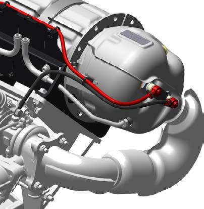
Sicherheit                                                                                        Easy Clean²

2        Sicherheit
2.1      Gerätespezifische Sicherheitshinweise

                            VORSICHT
                      Schnittgefahr!
                      Scharfe Kanten am Dieselpartikelfilter.
                       ▪ Schutzausrüstung (Handschuhe) tragen.

                            GEFAHR
                      Feuergefahr durch heiße Abgasanlage.
                      Wenn brennbare Materialien mit dem Abgasstrom oder der heißen Abgasanlage in Be-
                      rührung kommen, können sich diese Materialien entzünden.
                       ▪ Brennbare Materialien von der Abgasanlage fern halten.
                       ▪ Motor (Abgasstrom bzw. heiße Abgasanlage) nicht in direkter Nähe von brennbaren
                          Materialien betreiben.

                            VORSICHT
                      Verbrennungsgefahr.
                      Während des Regenerationsprozesses wird der Dieselpartikelfilter und das Auspuffsys-
                      tem sehr heiß. Bei Arbeiten am heißen Auspuffsystem besteht Verbrennungsgefahr.
                       ▪ Dieselpartikelfilter und Auspuffsystem abkühlen lassen.
                       ▪ Schutzhandschuhe tragen.

                            GEFAHR
                      Lebensgefahr, Verletzungsgefahr oder Gefahr von Sachschäden durch falsche
                      Anwendung von Batterien.
                       ▪ Kein Werkzeug oder sonstige Metallgegenstände auf die Batterie legen.
                       ▪ Vor jeder Durchführung von Arbeiten an der elektrischen Anlage immer den Minus-
                         Pol der Batterie abklemmen.
                       ▪ Nie Pluspol (+) und Minuspol (-) der Batterie vertauschen.
                       ▪ Beim Einbau der Batterie zuerst Plusleitung dann Minusleitung anschließen.
                       ▪ Beim Ausbau zuerst Minusleitung dann Plusleitung lösen.
                       ▪ Unbedingt Kurzschlüsse und Massekontakt stromführender Kabel vermeiden.
                       ▪ Bei Störungen sollten die Kabelanschlüsse auf guten Kontaktschluss überprüft wer-
                         den.

                      HINWEIS
                      Unsachgemäße Handhabung

                 i    Der Kunde ist für die Demontage bzw. Montage des Dieselpartikelfilters selbst verant-
                      wortlich. Die Sensorik und Verrohrung vom Dieselpartikelfilter muss vom Alt-Teil über-
                      nommen werden. Die Glühkerzen bleiben davon unberührt.
                      Die Motorenfabrik Hatz GmbH & Co. KG übernimmt keine Gewährleistung/Haftung für
                      den unsachgemäßen Aus- und Einbau des Dieselpartikelfilters.

4                                                                                                       HATZ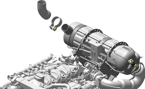
Easy Clean²                                                                               Montageanleitung

3       Montageanleitung
3.1     Demontage Dieselpartikelfilter chassisfest 12V / 24V
        Vorgehensweise
              Schritt    Beschreibung
                   1     Minusleitung von der Batterie abklemmen.

                   2     V-Bandschelle (A) lösen und die Abgasverrohrung (B) am Abgaseintritt des Diesel-
                         partikelfilters (DPF) herausziehen.

                   3     Das Abgasrohr (C) am Abgasaustritt des Dieselpartikelfilters (DPF) herausziehen.
                         Hierzu Sechskantmutter (A) lösen und die Befestigungsschelle (B) lockern.

HATZ                                                                                                        5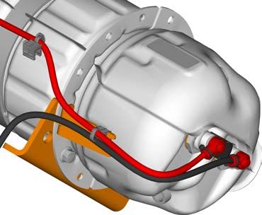
Montageanleitung                                                                            Easy Clean²

                   4   Die elektrischen Anschlüsse 12V (Nur bei Ausführung Activ Premium) entfer-
                       nen:
                       Zuerst den Kabelbinder (A) am Kabelhalterblech entfernen. Anschließend die Plus-
                       Leitungen (B) abklemmen: Schutzkappen (1) abziehen, Flanschmuttern (2) lösen
                       und die Kabelschuhe (3) der Plus-Leitungen inkl. Schutzkappen von den Glühker-
                       zen entfernen. Danach die Masse-Leitung (C) abklemmen.

                       * Bei Ausführung Activ, werden die gezeigten elektrischen Anschlüsse nicht
                       verbaut. In diesem Fall weiter mit Schritt 5.

                       Die elektrischen Anschlüsse 24V (Nur bei Ausführung Activ Premium) entfer-
                       nen:
                       Zuerst den Kabelbinder (A) am Kabelhalterblech entfernen. Anschließend die Plus-
                       Leitung (B) und die Masse-Leitung (C) abklemmen: Schutzkappen (1) abziehen,
                       Flanschmuttern (2) lösen und die Kabelschuhe (3) der Leitungen inkl. Schutzkappe
                       von den Glühkerzen entfernen.

                       * Bei Ausführung Activ, werden die gezeigten elektrischen Anschlüsse nicht
                       verbaut. In diesem Fall weiter mit Schritt 5.

                       Sind alle Leitungen abgeklemmt, Befestigungsmuttern (2) wieder auf den Glühker-
                       zen (handfest) verschrauben.

6                                                                                                HATZ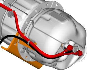
Easy Clean² Montageanleitung
5 Temperatursensoren demontieren:
Überwurfmuttern der Temperatursensoren (A) lösen und Sensoren aus den Diesel-
partikelfilter herausziehen. Die Temperatursensorstecker von Halterblech abste-
cken.
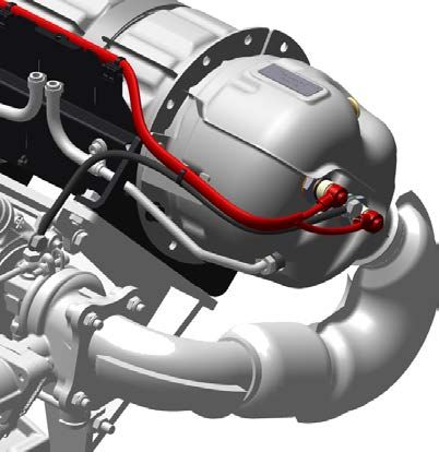
6 Druckrohre demontieren:
Die Schläuche (A) von den Druckrohren trennen. Hierzu die zwei Schlauchklemmen
lösen.
Hi Low
HATZ 7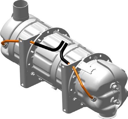
Montageanleitung Easy Clean²
Überwurfmuttern der Druckrohre (A) lösen und Rohre aus Öffnungen der Befesti-
gungswinkel herausziehen. Anschließend die Rohre aus dem Dieselpartikelfilter
herausziehen.
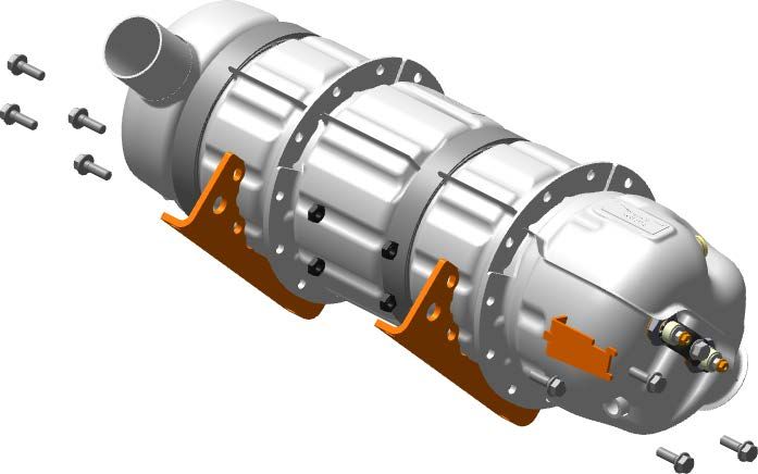
7 Demontage DPF-Befestigungswinkel und Kabelhalter:
Zuletzt, durch lösen der 8 SKT-Schrauben M8x30 (1) und SKT-Muttern M8, Befesti-
gungswinkel (A) und Kabelhalteblech (B) von Dieselpartikelfilter entfernen.
8 HATZEasy Clean² Montageanleitung
3.2 Montage Dieselpartikelfilter chassisfest 12V / 24V
Vorgehensweise
Schritt Beschreibung
1 Montage DPF-Befestigungswinkel und Kabelhalter:
Zuerst den Dieselpartikelfilter mit Kabelhalteblech (B) an Befestigungswinkeln (A)
mit 8 SKT-Schrauben M8x30 (1) und SKT-Muttern M8 befestigen.
Anzugs-Drehmoment 23 Nm.
2 Druckrohre montieren:
Gewinde der Druckrohre (A) reinigen, mit Castrol Optimol TA einstreichen und
durch die Öffnungen der Befestigungswinkel einfädeln. Im Anschluss die Druckroh-
re in die Gewindeöffnungen stecken und Überwurfmuttern, mit einem Anzugs-
Drehmoment von 45 ±5 Nm, anziehen.
HATZ 9Montageanleitung Easy Clean²
Anschließend die Druckrohre mit den zwei Schläuchen (A) verbinden und mit
Schlauchklemmen fixieren.
Die Seite Druck hoch (Hi) wird mit dem Druckrohr am DPF Eingang verbunden. Die
Seite Druck niedrig (Low) wird mit dem Druckrohr am DPF Ausgang verbunden. Die
Druckleitungen müssen stetig steigend zum Drucksensor verbaut werden (Druck-
sensorhöchster Punkt).
Hi Low
3 Temperatursensoren montieren:
Gewinde der Temperatursensoren (A) reinigen, mit Castrol Optimol TA einstreichen
und in die zwei dafür vorgesehenen Gewindelöcher stecken. Überwurfmuttern, mit
einem Anzugs-Drehmoment von 45 ±5 Nm, anziehen.
10 HATZEasy Clean² Montageanleitung
4 Die elektrischen Anschlüsse 12V (Nur bei Ausführung Activ Premium)
anschließen:
Kabelschuhe (3) der Plus-Leitungen (B) auf die Glühkerzen stecken und mit
Flanschmutter M5 (2) festschrauben. Anzugs-Drehmoment Flanschmutter 4Nm.
Anschließend Schutzkappe (1) über die Flanschmutter ziehen.
Masse-Leitung (Ø10 mm²) (C) auf das Masse Verbindungsblech schrauben.
* Bei Ausführung Activ, werden die gezeigten elektrischen Anschlüsse nicht
verbaut. In diesem Fall weiter mit Schritt 5.
Die elektrischen Anschlüsse 24V (Nur bei Ausführung Activ Premium)
anschießen:
Kabelschuh (3) der Plus-Leitung (B) sowie der Masse-Leitung (C) auf Glühkerze
schrauben und mit Flanschmutter M5 (2) festschrauben. Anzugs-Drehmoment
Flanschmutter 4Nm.
Anschließend Schutzkappe (1) über Flanschmutter ziehen.
Bei der 24V Ausführung werden die zwei Glühkerzen in Reihe geschalten. Zwi-
schen den beiden Glühkerzen befindet sich ein Isolierschlauch.
* Bei Ausführung Activ, werden die gezeigten elektrischen Anschlüsse nicht
verbaut. In diesem Fall weiter mit Schritt 5.
Die elektrischen Leitungen (12 / 24V) der Zusatzheizung am Kabelblech (A) mit Ka-
belbinder befestigen. Die Leitungen müssen nach maximal 250 mm mechanisch
befestigt werden um sie vor Schub-, Zug- und Vibrationskräften zu schützen (Zug-
entlastung).
HATZ 11Montageanleitung Easy Clean²
5 Die Abgasverrohrung (C) mit der Befestigungsschelle (B) auf den Abgasaustritt
DPF stecken und durch festziehen der Sechskantmutter (A) fixieren.
6 Die Abgasverrohrung (B) am Abgaseintritt DPF einführen und mit der V-Bandschel-
le (A) befestigen. Anzugs-Drehmoment V- Bandschelle: 9 ± 1 Nm.
7 Zuletzt Minusleitung wieder an die Batterie anklemmen.
12 HATZEasy Clean² Montageanleitung
3.3 Demontage Dieselpartikelfilter motorfest 12V / 24V
Vorgehensweise
Schritt Beschreibung
1 Zuerst Minusleitung von der Batterie abklemmen.
2 Die elektrischen Anschlüsse 12V (Nur bei Ausführung Activ Premium) ent-
fernen:
Zuerst den Kabelbinder (A) am Kabelhalterblech entfernen. Anschließend die
Plus-Leitungen (B) abklemmen: Schutzkappen (1) abziehen, Flanschmuttern (2)
lösen und die Kabelschuhe (3) der Plus-Leitungen inkl. der Schutzkappen von den
Glühkerzen entfernen. Danach die Masse-Leitung (C) abklemmen.
* Bei Ausführung Activ, werden die gezeigten elektrischen Anschlüsse nicht
verbaut. In diesem Fall weiter mit Schritt 5.
HATZ 13Montageanleitung Easy Clean²
Die elektrischen Anschlüsse 24V (Nur bei Ausführung Activ Premium) ent-
fernen:
Zuerst den Kabelbinder (A) am Kabelhalterblech entfernen. Anschließend die
Plus-Leitung (B) und die Masse-Leitung (C) abklemmen: Schutzkappen (1) abzie-
hen, Flanschmuttern (2) lösen und die Kabelschuhe (3) der Leitungen inkl.
Schutzkappen abnehmen.
* Bei Ausführung Activ, werden die gezeigten elektrischen Anschlüsse nicht
verbaut. In diesem Fall weiter mit Schritt 5.
Sind alle Leitungen abgeklemmt, Befestigungsmuttern (2) wieder auf den Glühker-
zen (handfest) verschrauben.
3 Das Abgasrohr (C) am Abgasaustritt DPF herausziehen. Hierzu Sechskantmutter
(A) lösen und die Befestigungsschelle (B) lockern.
14 HATZEasy Clean² Montageanleitung
4 V-Bandschelle (B) demontieren und Abgasrohr (1) vom Dieselpartikelfilter abzie-
hen. Anschließend Befestigungskonsole (A) abschrauben.
5 Temperatursensoren demontieren:
Überwurfmuttern der Temperatursensoren (A) lösen und aus Dieselpartikelfilter
herausziehen.
HATZ 15Montageanleitung Easy Clean²
6 Druckrohre demontieren:
Zuerst Überwurfmuttern der Druckrohre (A) lösen. Anschließend Befestigungs-
schellen (1) von Sensorikhalteblech (C) abschrauben, die Schläuche von den
Druckrohren abziehen und die Rohre durch die Öffnung der Befestigungswinkel
(D) herausziehen.
Demontage Befestigungswinkel und Kabelhalter:
Zuletzt Kabelhalteblech (B), Sensorikhalteblech (C) und Befestigungswinkeln (D)
von Dieselpartikelfilter abschrauben.
3.4 Montage Dieselpartikelfilter motorfest 12V / 24V
Vorgehensweise
Schritt Beschreibung
1 Vormontage Dieselpartikelfilter „motorfest“
Montage Befestigungswinkel und Kabelhalter:
Zuerst den Dieselpartikelfilter mit Kabelhalteblech (B), Sensorikhalteblech (C) und
Befestigungswinkeln (D) mit 8 SKT-Schrauben M8x30 (1) und SKT-Muttern M8
handfest verschrauben.
Montage Druckrohre:
Anschließend Gewinde der Druckrohre (A) reinigen, mit Castrol Optimol TA einstrei-
chen und durch Öffnung der Befestigungswinkel (D) führen. Zuletzt die Druckrohre
in die Gewindeöffnungen stecken und Überwurfmuttern mit einem Anzugs-Dreh-
moment von 45 ±5 Nm, anziehen
Schläuche mit Druckrohren verbinden. Die Druckrohre mit Befestigungsschellen (1)
und Befestigungsschrauben M6x12 am Sensorikhalteblech festschrauben.
16 HATZEasy Clean² Montageanleitung
2 Temperatursensoren montieren:
Gewinde der Temperatursensoren (A) reinigen, mit Castrol Optimol TA einstreichen
und in die zwei dafür vorgesehenen Gewindelöcher stecken. Überwurfmuttern, mit
einem Anzugs-Drehmoment von 45 ±5 Nm, anziehen
3 Vormontierten DPF mit Befestigungskonsole (A) handfest verschrauben. Abgasrohr
DPF Eintritt (1) mit DPF Eingang mittels V-Bandschelle (B) handfest verschrauben.
HATZ 17Montageanleitung Easy Clean²
4 Das Abgasrohr (C) am Abgasaustritt DPF einstecken. Mit SKT-Mutter (A) Befesti-
gungsschelle (B) montieren.
5 Die elektrischen Anschlüsse 12V (Nur bei Ausführung Activ Premium) an-
schließen:
Kabelschuhe (3) der Plus-Leitungen (B) auf die Glühkerzen stecken und mit
Flansch-mutter M5 (2) festschrauben, anschließend Schutzkappe (1) über Flansch-
mutter ziehen. Anzugs-Drehmoment Flanschmutter 4Nm.
Masse-Leitung (Ø10 mm²) (C) auf das Masse Verbindungsblech schrauben.
* Bei Ausführung Activ, werden die gezeigten elektrischen Anschlüsse nicht
verbaut. In diesem Fall weiter mit Schritt 5.
18 HATZEasy Clean² Montageanleitung
Die elektrischen Anschlüsse 24V (Nur bei Ausführung Activ Premium) an-
schließen:
Kabelschuh (3) der Plus-Leitung (B) sowie der Masse-Leitung (C) auf Glühkerze
schrauben und mit Flanschmutter M5 (2) festschrauben, anschließend Schutzkappe
(1) über Flanschmutter ziehen. Anzugs-Drehmoment Flanschmutter 4Nm.
Bei der 24V Ausführung werden die zwei Glühkerzen in Reihe geschalten. Zwi-
schen den beiden Glühkerzen befindet sich ein Isolierschlauch.
* Bei Ausführung Activ, werden die gezeigten elektrischen Anschlüsse nicht
verbaut. In diesem Fall weiter mit Schritt 5.
Die elektrischen Leitungen (12 / 24V) der Zusatzheizung am Kabel-Halteblech (A)
mit Kabelbinder befestigen. Die Leitungen müssen nach maximal 250 mm me-
chanisch befestigt werden um sie vor Schub-, Zug- und Vibrationskräften zu schüt-
zen (Zugentlastung).
HATZ 19Montageanleitung Easy Clean²
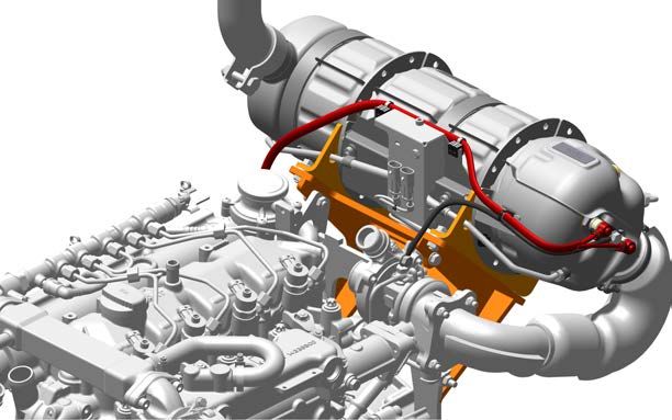
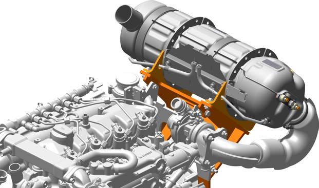
6 Vormontierten Dieselpartikelfilter mit Befestigungskonsole verschrauben (siehe fol-
gende Anzugsreihenfolge).
Anzugsreihenfolge der Befestigungskonsole und DPF-System:
1.Schraubpunkte A (M10) dann B (M8) festziehen.
2.Darauf achten, dass der Kompensator am Eingangsrohr unverspannt und nicht
verdreht eingebaut ist.
3.Schraubpunkt 1 auf Drehmoment 23 Nm anziehen.
4.Schraubpunkt 2 auf Drehmoment 23 Nm anziehen.
5.Schraubpunkt 3 auf Drehmoment 9 ±1 Nm anziehen.
7 Zuletzt Minusleitung an die Batterie anklemmen.
20 HATZEasy Clean² Table of Contents Table of Contents 1 Notices...................................................................................................................................................... 22 2 Safety ........................................................................................................................................................ 23 2.1 Device-specific safety instructions ............................................................................................................................... 23 3 Installation instructions .......................................................................................................................... 24 3.1 Removing the diesel particulate filter, chassis-mounted 12 V/24 V ............................................................................. 24 3.2 Installing the diesel particulate filter, chassis-mounted 12 V/24 V ............................................................................... 28 3.3 Removing of the diesel particulate filter, engine-mounted 12 V/24 V........................................................................... 32 3.4 Installing the diesel particulate filter, engine-mounted 12 V/24 V................................................................................. 35 HATZ 21
Notices                                                                                                  Easy Clean²

1         Notices
          Contact data
               © 2021
               Motorenfabrik HATZ
               Ernst-Hatz-Straße 16
               94099 Ruhstorf
               Germany
               Tel. +49 (0)8531 319-0
               Fax +49 (0)8531 319-418
               marketing@hatz-diesel.de
               www.hatz-diesel.com
               All rights reserved!

          Copyright
               The copyright for this manual rests entirely with Motorenfabrik HATZ, Ruhstorf.
               This manual may only be copied or distributed if written approval has been received. This also ap-
               plies to the copying or distribution of excerpts of this manual. The same conditions apply to distribu-
               tion of this manual to third parties in digital form.

22                                                                                                            HATZ
Easy Clean² Safety
2 Safety
2.1 Device-specific safety instructions
CAUTION
Danger of cutting!
Sharp edges on the diesel particulate filter.
▪ Wear personal protective equipment (gloves).
DANGER
Danger of fire from hot exhaust gas system.
If inflammable materials come into contact with the exhaust gas flow or the hot exhaust
gas system, these materials can ignite.
▪ Keep inflammable materials away from the exhaust gas system.
▪ Do not operate the engine (exhaust flow or hot exhaust gas system) in the direct
vicinity of combustible materials.
CAUTION
Danger of burns.
During the regeneration process, the diesel particulate filter and the exhaust system be-
come very hot. There is a danger of burns when working on a hot exhaust system.
▪ Let the diesel particulate filter and exhaust system cool down.
▪ Wear safety gloves.
DANGER
Danger to life, danger of injury or danger of property damage due to incorrect use
of batteries.
▪ Do not place tools or other metal objects on the battery.
▪ Before performing work on the electrical equipment, always disconnect the negative
battery terminal.
▪ Never swap the positive (+) and negative (–) battery terminals.
▪ When installing the battery, first connect the positive cable and then the negative
cable.
▪ When removing the battery, first disconnect the negative cable and then the posi-
tive cable.
▪ It is imperative to prevent short circuits and mass contact of current carrying cables.
▪ If faults occur, check the cable connections for good contact.
NOTICE
Improper handling
i The customer is responsible for the removal and installation of the diesel particulate fil-
ter. The sensors and pipes of the diesel particulate filter must be taken over from the old
part. The glow plugs are unaffected by this.
Motorenfabrik Hatz GmbH & Co. KG does not provide a warranty or assume responsi-
bility for incorrect removal and installation of the diesel particulate filter.
HATZ 23Installation instructions Easy Clean²
3 Installation instructions
3.1 Removing the diesel particulate filter, chassis-mounted 12 V/24 V
Procedure
Step Description
1 Disconnect the negative line from the battery.
2 Release the V clip (A) and pull the exhaust pipe (B) out of the exhaust intake of the
diesel particulate filter (DPF).
3 Pull the exhaust pipe (C) out of the exhaust outlet of the DPF. To do so, release the
hex nut (A) and loosen the fastening clip (B).
24 HATZEasy Clean² Installation instructions
4 Remove the 12 V electrical connections (only for the Activ Premium model):
First remove the cable tie (A) from the cable retaining plate. Then detach the posi-
tive lines (B): pull off the protective caps (1), release the flange nuts (2) and remove
the cable lugs (3) of the positive lines along with the protective caps from the glow
plugs. Then detach the ground line (C).
* In the Activ model, the electrical connections shown are not installed. In this
case, continue with step 5.
Remove the 24 V electrical connections (only for the Activ Premium model):
First remove the cable tie (A) from the cable retaining plate. Then detach the posi-
tive line (B) and the ground line (C): pull off the protective caps (1), release the
flange nuts (2) and remove the cable lugs (3) of the lines along with the protective
cap from the glow plugs.
* In the Activ model, the electrical connections shown are not installed. In this
case, continue with step 5.
After all lines have been detached, screw the fastening nuts (2) back onto the glow
plugs (hand-tight).
HATZ 25Installation instructions Easy Clean²
5 Remove the temperature sensors:
Release the union nuts of the temperature sensors (A) and pull the sensors out of
the DPF. Unplug the temperature sensor plugs from the retaining plate.
6 Remove the pressure pipes:
Disconnect the hoses (A) from the pressure pipes. To do so, release the two hose
clips.
Hi Low
26 HATZEasy Clean² Installation instructions
Release the union nuts of the pressure pipes (A) and pull the pipes out of the open-
ings of the angle brackets. Then pull the pipes out of the DPF.
7 Remove the angle brackets of the DPF and the cable retaining plate:
Finally, remove the angle brackets (A) and the cable retaining plate (B) from the
DPF by releasing the 8 hex screws M8x30 (1) and hex nuts M8.
HATZ 27Installation instructions Easy Clean²
3.2 Installing the diesel particulate filter, chassis-mounted 12 V/24 V
Procedure
Step Description
1 Install the angle brackets of the DPF and the cable retaining plate:
First attach the DPF with the cable retaining plate (B) to the angle brackets (A) us-
ing the 8 hex screws M8x30 (1) and hex nuts M8.
Tightening torque 23 Nm.
2 Install the pressure pipes:
Clean the threads of the pressure pipes (A), coat with Castrol Optimol TA and
thread through the openings of the angle brackets. Then insert the pressure pipes
into the threaded openings and tighten the union nuts with a tightening torque of
45 ±5 Nm.
28 HATZEasy Clean² Installation instructions
Then connect the pressure pipes with the two hoses (A) and secure them with the
hose clips.
The high-pressure side (Hi) is connected to the DPF input with the pressure pipe.
The low-pressure side (Low) is connected to the DPF output with the pressure pipe.
The pressure lines must be installed in such a way that they rise continuously rela-
tive to the pressure sensor (the pressure sensor is the highest point).
Hi Low
3 Install the temperature sensors:
Clean the temperature sensor threads (A), coat with Castrol Optimol TA and insert
them into the two provided threaded holes. Tighten the union nuts with a tightening
torque of 45 ±5 Nm.
HATZ 29Installation instructions Easy Clean²
4 Connect the 12 V electrical connections (only for the Activ Premium model):
Attach the cable lugs (3) of the positive lines (B) to the glow plugs and secure using
the flange nut M5 (2). Tightening torque of the flange nut 4 Nm. Then mount the
protective cap (1) on the flange nut.
Screw the ground line (Ø10 mm²) (C) on the ground connecting plate.
* In the Activ model, the electrical connections shown are not installed. In this
case, continue with step 5.
Remove the 24 V electrical connections (only for the Activ Premium model):
Screw the cable lug (3) of the positive line (B) and the ground line (C) onto the glow
plug and secure with the flange nut M5 (2). Tightening torque of the flange nut
4 Nm.
Then mount the protective cap (1) on the flange nut.
In the 24 V model, two glow plugs are connected in series. An insulating hose is lo-
cated between the two glow plugs.
* In the Activ model, the electrical connections shown are not installed. In this
case, continue with step 5.
Connect the electric lines (12/24 V) of the auxiliary heating to the cable retaining
plate (A) using a cable tie. The lines must be mechanically fastened after no more
than 250 mm to protect them against pulling, pushing and vibration forces (strain re-
lief).
30 HATZEasy Clean² Installation instructions
5 Mount the exhaust pipe (C) on the exhaust outlet of the DPF with the fastening
clip (B) and secure by tightening the hex nut (A).
6 Insert the exhaust pipe (B) into the exhaust intake of the DPF and attach using the
V clip (A). Tightening torque of the V clip: 9 ±1 Nm.
7 Finally, reconnect the negative line to the battery.
HATZ 31Installation instructions Easy Clean²
3.3 Removing of the diesel particulate filter, engine-mounted 12 V/24 V
Procedure
Step Description
1 First disconnect the negative line from the battery.
2 Remove the 12 V electrical connections (only for the Activ Premium model):
First remove the cable tie (A) from the cable retaining plate. Then detach the posi-
tive lines (B): pull off the protective caps (1), release the flange nuts (2) and re-
move the cable lugs (3) of the positive lines along with the protective caps from
the glow plugs. Then detach the ground line (C).
* In the Activ model, the electrical connections shown are not installed. In
this case, continue with step 5.
32 HATZEasy Clean² Installation instructions
Remove the 24 V electrical connections (only for the Activ Premium model):
First remove the cable tie (A) from the cable retaining plate. Then detach the posi-
tive line (B) and the ground line (C): pull off the protective caps (1), release the
flange nuts (2) and remove the cable lugs (3) of the lines along with the protective
caps.
* In the Activ model, the electrical connections shown are not installed. In
this case, continue with step 5.
After all lines have been detached, screw the fastening nuts (2) back onto the
glow plugs (hand-tight).
3 Pull the exhaust pipe (C) out of the exhaust outlet on the DPF. To do so, release
the hex nut (A) and loosen the fastening clip (B).
HATZ 33Installation instructions Easy Clean²
4 Remove the V clip (B) and pull the exhaust pipe (1) off of the DPF. Then unscrew
the fastening bracket (A).
5 Remove the temperature sensors:
Release the union nuts of the temperature sensors (A) and pull the sensors out of
the DPF.
34 HATZEasy Clean² Installation instructions
6 Remove the pressure pipes:
First release the union nuts of the pressure pipes (A). Then unscrew the fastening
clips (1) from the sensor retaining plate (C), pull the hoses off of the pressure
pipes and pull the pipes out through the openings in the angle brackets (D).
Remove the angle brackets and the cable retaining plate:
Finally, unscrew the cable retaining plate (B), sensor retaining plate (C) and angle
brackets (D) from the DPF.
3.4 Installing the diesel particulate filter, engine-mounted 12 V/24 V
Procedure
Step Description
1 Pre-assembly of the diesel particulate filter, "engine-mounted"
Install the angle brackets and cable retaining plate:
First screw the cable retaining plate (B), sensor retaining plate (C) and angle brack-
ets (D) onto the DPF hand-tight using 8 hex screws M8x30 (1) and hex nuts M8.
Install the pressure pipes:
Then clean the threads of the pressure pipes (A), coat with Castrol Optimol TA and
thread through the openings of the angle brackets (D). Finally, insert the pressure
pipes into the threaded openings and tighten the union nuts with a tightening
torque of 45 ±5 Nm.
Connect the hoses with the pressure pipes. Secure the pressure pipes on the sen-
sor retaining plate using the fastening clips (1) and fastening screws M6x12.
HATZ 35Installation instructions Easy Clean²
2 Install the temperature sensors:
Clean the temperature sensor threads (A), coat with Castrol Optimol TA and insert
them into the two provided threaded holes. Tighten the union nuts with a tightening
torque of 45 ±5 Nm.
3 Screw the pre-assembled DPF onto the fastening bracket (A) hand-tight. Screw the
infeed side of the DPF exhaust pipe (1) onto the DPF inlet using the V clip (B) hand-
tight.
36 HATZEasy Clean² Installation instructions
4 Insert the exhaust pipe (C) into the exhaust outlet on the DPF. Mount the fastening
clip (B) using the hex nut (A).
5 Connect the 12 V electrical connections (only for the Activ Premium model):
Attach the cable lugs (3) of the positive lines (B) to the glow plugs, screw tight using
the flange nut M5 (2) and then mount the protective cap (1) on the flange nut.
Tightening torque of the flange nut 4 Nm.
Screw the ground line (Ø10 mm²) (C) onto the ground connecting plate.
* In the Activ model, the electrical connections shown are not installed. In this
case, continue with step 5.
HATZ 37Installation instructions Easy Clean²
Connect the 24 V electrical connections (only for the Activ Premium model):
Screw the cable lug (3) of the positive line (B) and the ground line (C) onto the glow
plug, secure with the flange nut M5 (2) and mount the protective cap (1) on the
flange nut. Tightening torque of the flange nut 4 Nm.
In the 24 V model, two glow plugs are connected in series. An insulating hose is lo-
cated between the two glow plugs.
* In the Activ model, the electrical connections shown are not installed. In this
case, continue with step 5.
Connect the electric lines (12/24 V) of the auxiliary heating to the cable retaining
plate (A) using a cable tie. The lines must be mechanically fastened after no more
than 250 mm to protect them against pulling, pushing and vibration forces (strain re-
lief).
38 HATZEasy Clean² Installation instructions
6 Screw the pre-assembled DPF onto the fastening bracket (see the following tighten-
ing sequence).
Tightening sequence of the fastening bracket and DPF system:
1.Tighten the screw points A (M10) followed by B (M8).
2.Ensure that the compensator at the input pipe is neither strained nor twisted.
3.Tighten the screw point 1 to torque 23 Nm.
4.Tighten the screw point 2 to torque 23 Nm.
5.Tighten the screw point 3 to torque 9 ±1 Nm.
7 Finally, connect the negative line to the battery.
HATZ 39Motorenfabrik Hatz GmbH & Co. KG
Ernst-Hatz-Str. 16
94099 Ruhstorf a. d. Rott
Deutschland
Tel. +49 8531 319-0
Fax. +49 8531 319-418
marketing@hatz-diesel.de
www.hatz-diesel.com
0000 043 682 00 - 02.2021
Printed in Germany
DE / EN
CREATING POWER SOLUTIONS.Sie können auch lesen