Montagesockel & Dachdurchführungen
←
→
Transkription von Seiteninhalten
Wenn Ihr Browser die Seite nicht korrekt rendert, bitte, lesen Sie den Inhalt der Seite unten
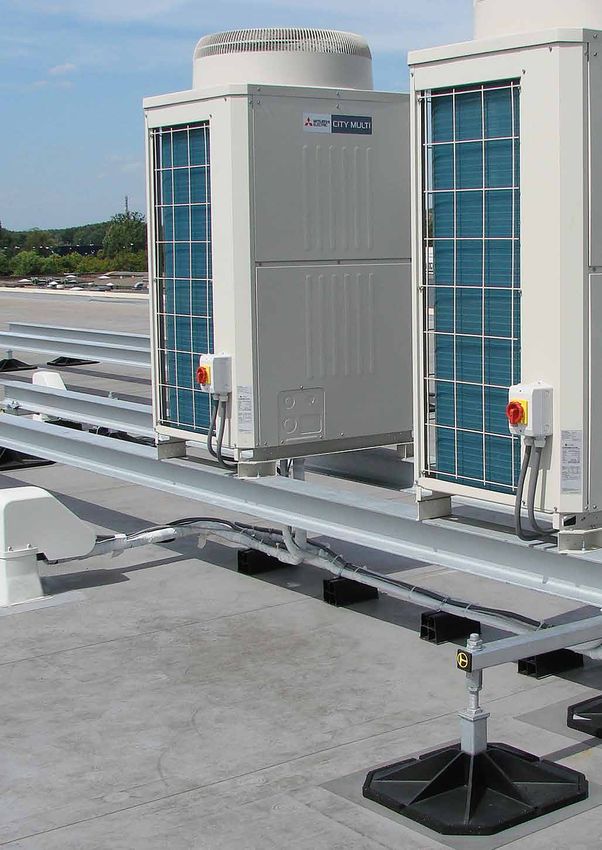
Montagesockel
              & Dachdurchführungen

©Linum   Montagesockel & Dachdurchführungen   69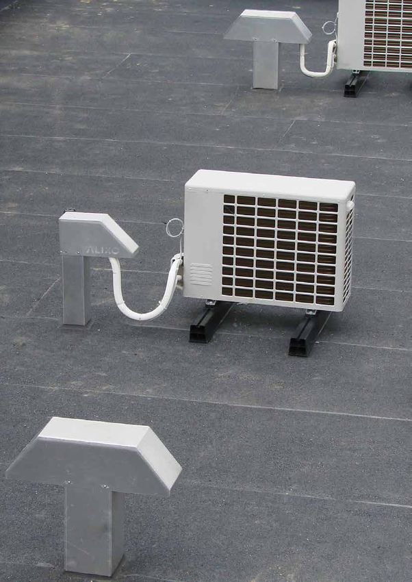
Montageschienen

                              Montageschienen aus schwarzem PVC
                              •   Strukturiertes Trageprofil
                              •   Verträgt hohe Temperaturen
                              •   Bis 450 kg/m (statisch) belastbar
                              •   Für jede Außeneinheit geeignet
                              •   Antirutsch-Folie auf der Unterseite
                              •   MGS-1035, MGS-1045 und MGS-1100 werden pro Set verkauft
                                  & mit Bolzen geliefert

                              Art.-Nr.             Abmessungen         Sets/Karton
                              MGS-1035            350 x 105 x 95            6
                              MGS-1045            450 x 105 x 95            6
                              MGS-1100            1000 x 105 x 95           1

                              Art.-Nr.             Abmessungen            Meter
                              MGS-1200            2000 x 105 x 95           1

                              Zubehör für PVC-Montageschienen

                               Art.-Nr.       Beschreibung
                                              Endkappe - PVC - schwarz
                               MGS-9000
                                              (Set je 4 St.)

                        80                    Galvanisierte Montageplatte + Bolzenset
                 60            MGS-9001       (= Bolzen + Mutter + U-Scheiben) zur Bodenmontage
                                              des Montageprofils (Set je 4 St.)
      MGS-9000
                                              Bolzenset (Bolzen + U-Scheiben ) zur Befestigung der
                               MGS-9002
                                              Klima-Einheit an Montageschiene (Set je 4 St.)
                  MGS-9001

                                                                                       Alle Abmessungen in mm (LxBxH)

70                           Montagesockel & Dachdurchführungen                                             ©Linum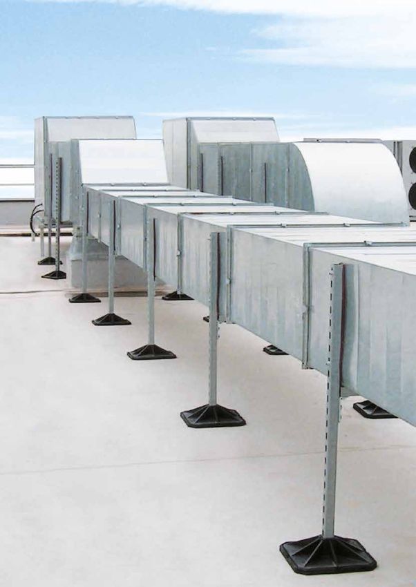
Montageschienen

                           Volle Montageschienen aus recycelten Kunststoffen
                           •   Wählen Sie aus 4 Typen
                           •   Für alle Außeneinheiten geeignet - Befestigung frei wählbar
                           •   Auf Anfrage auch in anderen Längen erhältlich
                           •   Zertifikate auf Anfrage verfügbar
                     B

                           Volle Montageschienen - Höhe 50 mm                                                100

                            Art.-Nr.             Abmessungen           St/Palette                  50
                            MGV-1045            450 x 100 x 50            100
                            MGV-1090            900 x 100 x 50             50
                            MGV-1180            1800 x 100 x 50           180

                           Volle Montageschienen - Höhe 60 mm                                               120

                            Art.-Nr.             Abmessungen           St/Palette                 60
                            MGV-2090            900 x 120 x 60            100
                            MGV-2180            1800 x 120 x 60            50

                           Volle Montageschienen - Höhe 100 mm                                               100

                            Art.-Nr.             Abmessungen           St/Palette
                            MGV-3090            900 x 100 x 100           100                      100
                            MGV-3180           1800 x 100 x 100            50

                           Volle Montageschienen - Höhe 60 mm                                               80

                            Art.-Nr.             Abmessungen           St/Palette                 60
                            MGV-4090          900 x 80 / 120 x 60         100
                                                                                                            120
                            MGV-4180          1800 x 80 / 120 x 60         50

             Innovative
               Lösung

Isolierte Sockel

                           Isolierter Sockel
                           •   Druckfester, galvanisierter Isoliersockel mit Styroporkern
                           •   An 4 Seiten abgekantet
                           •   Stoßdämpfend
                           •   Einfache Aufstellung; kein Mauerwerk oder zeitraubende Konstruktionen benötigt
                           •   Lange Lebensdauer
                           •   Schützt gegen Flüssigkeit und Schmutz
                           •   Auch für Heizkessel, Außeneinheiten, Ventilatoren geeignet
                           •   Tragkraft verteilt sich auf die gesamte Oberfläche

                           Art.-Nr.             Abmessungen          Tragkraft St/Karton St/Palette
                           MGS-8032            320 x 650 x 70         250 kg        1        60
                           MGS-8050            500 x 700 x 70        300 kg         1        40
                           MGS-8060            600 x 650 x 70        300 kg         1        40
                           MGS-8070            700 x 850 x 70         450 kg        1        20
                           MGS-8100            1000 x 650 x 70       500 kg         1        20
                           MGS-8130            1300 x 850 x 70        650 kg        1        20

                                                                                        Alle Abmessungen in mm (LxBxH)

©Linum                    Montagesockel & Dachdurchführungen                                                             71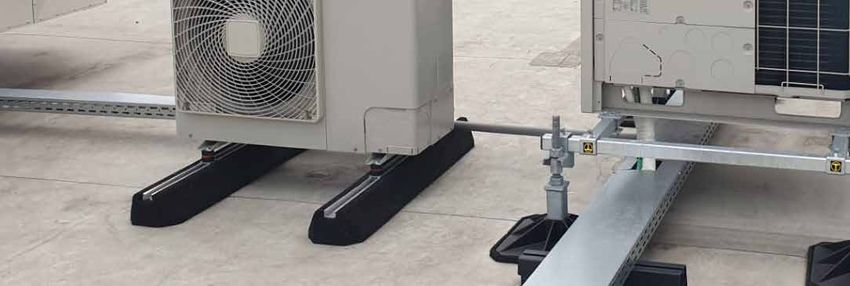
Big Foot Systems - Fix-it Foot

                               Fix-it Foot
                               • Fester Gummi-Sockel für Leitungen, Außeneinheiten oder Rohre
                                 auf Flachdächern oder flachen Oberflächen
                               • Aluminiumprofil (41 x 20 mm) in Fuß eingearbeitet, zur
                                 Befestigung des Zubehörs
                               • UV-beständig - Wasserfest - Vibrationsdämpfend
                               • Für den Innen- oder Außenbereich bei Temperaturen von
                                                                                                               Breite Montage-
                                 -40°C bis +80°C                                                             schiene 41 x 20 mm
                               • Lieferung ohne Befestigungsmaterial oder Montagezubehör

                                Art.-Nr.          Abmessungen        Tragkraft*         St/Pal.
                                BFF-1251         250 x 180 x 95           82 kg           250
                                BFF-1261         400 x 180 x 95           128 kg         200                        ALX-1902
                                BFF-1211         600 x 180 x 95           224 kg          140
                                BFF-1221         1000 x 180 x 95          295 kg          70
                                ALX-1902     Satz Einlegeschrauben (2 St.) M10 x 40 mm
                               *: statisch

                                                               BFF-1251
                                                                          BFF-1261
                                                                                     BFF-1211
                                                                                                BFF-1221

                               Fix-it Foot Unterlage
                               • Wählen Sie zwischen:
                                 - BFF-1211 und BFF-3211 (Einlegeschraube optional)
                                 - BFF-1221 und BFF-3221 (Einlegeschraube optional)
                               • Ideal für Wärmepumpen: gem. Montageanleitung der
                                 Hersteller

                    Gesamt-     Art.-Nr.          Abmessungen        Tragkraft*         St/Pal.
      BFF-1211       höhe
                                BFF-3211         600 x 180 x 125          224 kg          60
         +          220 mm
                                BFF-3221         1000 x 180 x 125         295 kg          40
      BFF-3211
                               *: statisch

                                                                                      BFF-3221
                                                                                                     BFF-1221
                               Fix-it Foot Low
                               • Besonders geeignet für die Montage von Solar-Paneele & Kabeltrassen:
                                 minimale Windlast durch geringe Aufbauhöhe

                                Art.-Nr.          Abmessungen        Tragkraft*        St/Pal.
                                BFF-1351         250 x 130 x 50           82 kg         480
                                BFF-1361         400 x 130 x 50       128 kg            480
                                BFF-1371         500 x 130 x 50       134 kg            320                         ALX-1902
                                ALX-1902     Satz Einlegeschrauben (2 St.) M10 x 40 mm
                               *: statisch

                                                                                  BFF-1351
                                                                                             BFF-1361
                                                                                                        BFF-1371

                                                                                                        Alle Abmessungen in mm

72                            Montagesockel & Dachdurchführungen                                                      ©Linum
Big Foot Systems - Fix-it Foot

                          Fix-it Foot "Go" Kits
                          • Wählen Sie zwischen:
                            - 2x BFF-1261 + 4 Einlegeschrauben
                            - 2x BFF-1211 + 4 Einlegeschrauben
                            - 2x BFF-1221 + 4 Einlegeschrauben

                           Art.-Nr.      Beschreibung                                                       St/Pal.
                           BFF-1269      Fix-it Foot "Go" 400 mm Kit: 2x BFF-1261 + 4 Einlegeschrauben        40
              BFF-1219     BFF-1219      Fix-it Foot "Go" 600 mm Kit: 2x BFF-1221 + 4 Einlegeschrauben        30
                           BFF-1229      Fix-it Foot "Go" 1000 mm Kit: 2x BFF-1211 + 4 Einlegeschrauben       20

                                                                                                 Mit Bändern
                                                                                                  gebündelt

                          Fix-it Foot Kits
                          • Wählen Sie zwischen:
                            - 2x BFF-1211 + 2x ALX-1902 (= 4 Einlegeschrauben)
                            - 2x BFF-1221 + 2x ALX-1902 (= 4 Einlegeschrauben)

                           Art.-Nr.      Beschreibung
                           BFF-1218      Fix-it Foot 600 mm Kit: 2x BFF-1211 + 2x ALX-1902
                           BFF-1228      Fix-it Foot 1000 mm Kit: 2x BFF-1221 + 2x ALX-1902
                                                                                                          ALX-1902
              BFF-1218     ALX-1902      Satz Einlegeschrauben (2 St.) M10 x 40 mm

                                                                                                  Verpackt in
                                                                                                 einem Karton

©Linum                   Montagesockel & Dachdurchführungen                                                           73
Alixo Foot
Alixo Foot
• Fester Gummi-Sockel für Leitungen, Außeneinheiten oder Rohre
auf Flachdächern oder flachen Oberflächen
• Möglichkeit zur Befestigung auf dem Boden
• Aluminiumprofil (41 x 20 mm) in Fuß eingearbeitet, zur
Befestigung des Zubehörs / Einheiten
• UV-beständig - Wasserfest - Vibrationsdämpfend Breite Montage-
• Für den Innen- oder Außenbereich bei Temperaturen von
C
schiene 41 x 20 mm
D
A
B
-40°C bis +80°C
Plan N°: Sabot 600 mm - V2
1
Tolérances Générales: ±
1/1
A3
155,7
• Individuell verpackt ohne Befestigungs- oder Montagematerial
Taille Feuille:
Roughness:
Feuille N°:
Sheet Size:
Draw N°:
Sheet N°:
Rugosité:
Ce plan est la propriété de RubberGreen et ne peut être utilisé,reproduit ou communiqué sans son autorisation écrite
Art.-Nr. Abmessungen Tragkraft* St/Pal.
8
ALX-1241 400 x 135 x 100 130 kg 216
Tel:+32(0)65/80.15.60 Fax:+32(0)65/63.49.08 Email:info@rubbergreen.be
This drawing is the exclusive property of RubberGreen and shall not be distibued or copied without
RubberGreen S.A Rue de la sucrerie 10 7080 Frameries - Belgium
ALX-1900
ALX-1211 600 x 135 x 100 195 kg 144
Approuvé par
rail
ALX-1221 1000 x 135 x 100 320 kg 108
7
ALX-1900 Satz Einlegeschrauben (2 St.) M10 x 30 mm
Titre : Sabot 600 mm avec
12
Vérifié par
*: statisch
Destination: Fabrication
144
7
Dessinateur
Gobert D.
Client : ALIXO
the written consent of RubberGreen
ECHELLE 1 : 3
COUPE A-A
7.92 Kg
CONFIDENTIAL
CONFIDENTIEL
24-07-20
6
Date
ALX-1241
Poids:
Matière:
Material:
Weight:
Rev.
600
280
ALX-1211
144
6
ALX-1221
B
B
R5
R5
C
C
Alixo High Foot
144
• Alixo High Foot, wählen Sie zwischen:
5
5
- ALX-1111 (Einlegeschraube optional)
36°
- ALX-1131 (Einlegeschraube optional)
119
20
100
Art.-Nr. Abmessungen Tragkraft* St/Pal.
ALX-1111 600 x 200 x 150 250 kg 80
ALX-1131 1200 x 200 x 150 250 kg 56
R5
4
4
R5
20 ALX-1900 Satz Einlegeschrauben (2 St.) M10 x 30 mm ALX-1900
125
200 *: statisch
ECHELLE 1 : 3
COUPE B-B
17,29
R 10
3
3
150
19,50
176,90
23
36°
52°
5
200
37
20
200 ALX-1111
A
A
2
2
10
ECHELLE 1 : 3
R
COUPE C-C
5°
ALX-1131
20
35 150
5
Optional - Schutzmatte
1
1
32
• Schutz für PVC-Dächer
24
12
Art.-Nr. Abm. Fuß Material
C
D
A
B
E
F
LAC-0353 650 x 200 Fleece
LAC-0354 1300 x 200 Fleece
Alle Abmessungen in mm
74 Montagesockel & Dachdurchführungen ©Linum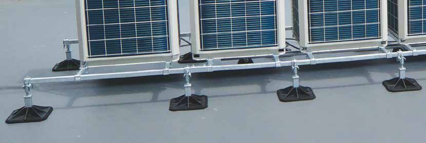
Alixo Foot

                              Alixo Foot Sets
                              • Alixo Foot Sets, wählen Sie zwischen:
                                - 2x ALX-1241 + 2x ALX-1900 (= 4 Einlegeschrauben)
                                - 2x ALX-1211 + 2x ALX-1900 (= 4 Einlegeschrauben)                                                   ALX-1900
                                - 2x ALX-1221 + 2x ALX-1900 (= 4 Einlegeschrauben)

                               Art.-Nr.      Beschreibung                                                                                   St/Pal.
                               ALX-1249      Alixo Foot 400 mm set: 2x ALX-1241 + 2x ALX-1900                                                   40
                               ALX-1219      Alixo Foot 600 mm Set: 2x ALX-1211 + 2x ALX-1900                                                   30
             ALX-1219          ALX-1229      Alixo Foot 1000 mm Set: 2x ALX-1221 + 2x ALX-1900                                                  20
                               ALX-1900      Satz Einlegeschrauben (2 St.) M10 x 30 mm

                                   Mit Bändern
                                    gebündelt

                              Alixo High Foot Kits
                              • Alixo High Foot kits, wählen Sie zwischen:
                                - 2x ALX-1111 + 4 Einlegeschrauben
                                - 2x ALX-1131 + 4 Einlegeschrauben

                               Art.-Nr.      Beschreibung
                               ALX-1119      Alixo High Foot 600 mm Kit: 2x ALX-1111 + 4 Einlegeschrauben
                               ALX-1139      Alixo High Foot 1200 mm Kit: 2x ALX-1131 + 4 Einlegeschrauben

                  ALX-1119         Mit Bändern
                                    gebündelt

                                                                                        1                            2                           3                    4

                                                                                 A                                           COUPE A-A
                                                                                                                            ECHELLE 1 : 4

                                                                                                                     M10
                                                                                                                                                R5
                                                                                                                                       R5

Universal-Foot                                                                                                  3°
                                                                                                            25

                                                                                                                           60

                                                                                 B
                                                                                                                           60°                                         CO
                                                                                                                                                                      ECH
                              Universal-Foot - Kautschuk                                                                        80         80
                                                                                                                                     B
                              • Stabiler Gummimontageblock zur Unterstützung von
                                Rohren und Kabeln
                              • Ausgestattet mit 3 M8-Metalleinsätzen zur Befestigung                                                                                 5
                                                                                                                                                          70°

                                                                                 C
                                                                                                                                                                60°
                                                                                                      190

                                einer Montageschiene oder von Gewindestangen                                A                                         A
                              • Profile oder Gewindestangen separat erhältlich
                              • Maximale Traglast: 120 kg
                                                                                                                                     B
                                                                                                                                     240

                               Art.-Nr.   Beschreibung               Abm. Fuß    D

                               ALX-1001   Universal-Foot 240         240 x 190
                                                                                     Ecrou Noyé M10
                                                                                                      Alle Abmessungen in mm

                                                                                 E

©Linum                       Montagesockel & Dachdurchführungen                                                                                                 75
Big Foot Systems - Multi Foot
Multi Foot - Polyamid
• Rechteckige PA-Füße für verschiedene Anwendungsmöglichkeiten:
Kabelrinnen, Profile (Rohr 41 x 41 mm), Gewindestangen (M10), ...
• Integrierte Antivibrationsmatte
• Schnelle und einfache Montage
• Profile oder Gewindestange nicht inklusive
4 5 6 7 8
1 2 3 4 5 6
OT DETAILS & PERFORMANCE RECOMMENDATIONS
A Art.-Nr. Beschreibung
PROJECT REF: Multi Foot
UNIT REF: N/A
Abm. Fuß St/Karton
Material grade: BS EN 10219-1:2006 (S235JR). Welding standard: BS EN ISO 15614-1. Galvanizing standard: BS EN ISO 1461:2009
Reference specification document "Custom Fabrication Specification" (BF-SPEC-050411) for further information
Reference specification document "Big Foot Systems Cross Bar Specification (BF-SPEC-230610) for further information
7 B9043 B9045 B9368 B6357 B6359
T 1000 FIX-IT FOOT LOW 250
250
FIX-IT FOOT LOW 400
400
FIX-IT FOOT LOW 500
500
MULTI FOOT 400
400
MULTI FOOT 600
600
BFF-2061 MultiA Foot 400
N/A
N/A
FOOT PRESSURE:
UDL:
400 x 180 400
4 A
2 10 16 19 3/4 16 24
130
5
130
5
130
5
180
7
220
8 3/4
BFF-2011 Multi Foot 600 600 x125220 150 125
3 102
50 50 50 80 80
2.0 2.0 2.0 3 3
1.2 2.5 4.6 1.7 2.5
2.6 5.5 10.1 3.7 5.5 B
82 128 134 259 474
ideal für Kabelrinnen,
180
181 282 295 571 1045
42
BRUFMA) OF AN ACCEPTABLE LOAD OF 35KN/M2 (5.1 PSI). PROJECT SPECIFIC DESIGN PARAMETERS
Gewindestangen (M10), 21
ENGTH (@
m/min) YIELD STRENGTH
COMPRESSIVE
STRENGTH (@ 20%) Profile (Rohr
B
41 x 41B9640
mm), ... 41 B
psi MPa psi MPa psi B9640
- - - 1.20 174 1 2 3 4 5 6
PROJECT REF: Multi Foot C Material grade: BS EN 10219-1:2006 (S235JR). Welding standard: BS EN ISO 15614-1. Galvanizing standard: BS EN ISO 1461:2009
Reference specification document "Custom Fabrication Specification" (BF-SPEC-050411) for further information
30458 250 36259 - -
Reference specification document "Big Foot Systems Cross Bar Specification (BF-SPEC-230610) for further information
UNIT REF: N/A
- 145 21030 - - 600
FOOT PRESSURE: N/A
A UDL: N/A 400 A
40 260 260 40
125 150 125 102
B9655
D
C C
180
220
42
42
Integrierte MULTI FOOT WILL
21 ACCOMODATE:
21
Antivibrationsmatte INTEGRATED MAT B9640 41x41 UNISTRUT (VERTICALLY)
B 41 B9640 41x21 UNISTRUT (HORIZONTALLY) B
41 B9655
40x20 CHANNEL (HORIZONTALLY) 102
E
10mm/12mm THREADED ROD (VERTICALLY)
TITLE:
Installation and application considerations REV DATE: 14/02/2017 1:5
600
SCALE:
should include health, safety and enviromental Multi Foot Technical Data Sheet
D
needs, regulations and standards, codes of
practice, climate conditions, installation A DRAWN: A SIMMANS A3 D
location, product orientation, evaluation of the DIMENSIONS IN mm U.O.S DWG No.
40 260 260 40
roof structure, composition, surface and
CHECKED:
MULTIFOOT 400
condition, ancillary and complimentary products
N WOOD
MULTIFOOT 400 and materials. Big Foot Systems recommend
that all rooftop products are handled and TOLERANCES: 0.0 ± 0.5mm U.O.S BFT-MFO.dwg
installed by suitably qualified persons. All
scheme designs are based on the use of Big Foot
THIS DRAWING IS COPYRIGHT AND
TITLE: Systems' products and materials only.
THE PROPERTY OF BIG FOOT SYSTEMS LIMITED
FIX-IT / MULTI FOOT SPECIFICATION SHEET Terms and conditions available on request
SHEET 2 OF 2
OR BESPOKE DESIGNS PLEASE CONTACT THE
BIG FOOT TECHNICAL OFFICE DWG NO. B9655 F
1 2 3 4 5 6
FM1005-01-01
+44(0)1323 844 355
TECHNICAL@BIGFOOTSUPPORT.COM C
THIS DRAWING IS COPYRIGHT AND C
WWW.BIGFOOTSUPPORT.COM THE PROPERTY OF BIG FOOT SYSTEMS LIMITED
220
42
4 5 6 7 8
MULTI FOOT WILL ACCOMODATE:
41x41 UNISTRUT (VERTICALLY)
41x21 UNISTRUT (HORIZONTALLY)
Stand Range 21
41 B9655
40x20 CHANNEL (HORIZONTALLY) 102
10mm/12mm THREADED ROD (VERTICALLY) • Modulares Grundmontagesystem
•
Installation and application considerations
should include health, safety and enviromental
Zur Montage von verschiedenen
REV DATE:
A3
14/02/2017 Einheiten
SCALE:
Multi Foot Technical Data Sheet 1:5
TITLE:
A
needs, regulations and standards, codes of
D D
• Aussparungen an den Füßen zur Befestigung im Boden
practice, climate conditions, installation DRAWN: A SIMMANS
location, product orientation, evaluation of the DIMENSIONS IN mm U.O.S DWG No.
roof structure, composition, surface and
CHECKED:
condition, ancillary and complimentary products
N WOOD
and materials. Big Foot Systems recommend
that all rooftop products are handled and BFT-MFO.dwg TOLERANCES: 0.0 ± 0.5mm U.O.S
• Nicht geeignet für Einheiten auf Flachdächern (mit voller Windbelastung)
installed by suitably qualified persons. All
scheme designs are based on the use of Big Foot
Systems' products and materials only. THIS DRAWING IS COPYRIGHT AND
Terms and conditions available on request THE PROPERTY OF BIG FOOT SYSTEMS LIMITED
SHEET 2 OF 2
1 2
• Feuerverzinkter
3
Stahl
4 5 6
• Einstellbare Traverse
• Schnelle und einfache Montage
• Rahmen mit extra langen Traversen für VRV/VRF auf Anfrage verfügbar
Mini Split Stand Range
• Universelle Traverse (41 x 41 mm) zur flexiblen Befestigung von
Standard Einlegeschrauben
• Höhe 305 mm, Füße: 200 x 200 mm
• Länge Traverse: 990 mm
• Anti-Vibrations-Befestigungsschrauben
• Auf Anfrage: Anbaumöglichkeiten mit einem Anbaurahmen
BFS-2001
Art.-Nr. Beschreibung Abm. Fuß Tragkraft Gewicht
Big Foot Mini Split Low Stand Range
BFS-2001 200 x 200 175 kg 20 kg
700 x 1125 x 305 (LxBxH)
VRV/VRF Stand Range
• Universelle Traverse (41 x 41 mm) zur flexiblen Befestigung von
Standard Einlegeschrauben
• Höhe 305 mm, Füße: 200 x 200 mm
• Länge Traverse: 990 mm
• Auf Anfrage: Anbaumöglichkeiten mit einem Anbaurahmen
• Komplettes Befestigungsset inklusive
BFS-2100
Art.-Nr. Beschreibung Abm. Fuß Tragkraft Gewicht
Big Foot VRV/VRF Stand Range
BFS-2100 200 x 200 600 kg 35 kg
1230 x 1360 x 305 (LxBxH)
Alle Abmessungen in mm
76 Montagesockel & Dachdurchführungen ©Linum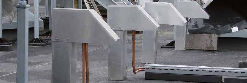
Big Foot Systems - H-Rahmenstellfüße & Zubehör

                                   H-Rahmenstellfüße ohne Profile
                                   • Zum Aufstellen unter Lüftungskanälen oder Rohrleitungen
                                   • Inhalt des Sets BFS-5300: 2 Füße mit integrierten Antivibrationsmatten,
                                     4 Winkelstücke, 8 Schrauben + Muttern (M10), für Profil 38 x 40 oder 41 x 41 mm
                                   • Inhalt des Sets BFS-5400 & BFS-5600: 2 Füße, 2 Antivibrationsmatten,
                                     2 heavy duty Winkelstücke, 4 Schrauben + Muttern (M10), für Profil 41 x 41 mm
                                   • Profile nicht inklusive

                                    Art.-Nr.       Beschreibung                                        Tragkraft pro Füß
                                    BFS-5300       H-Rahmenstellfüße Set 305 x 305 mm                        150 kg
                                    BFS-5400       H-Rahmenstellfüße Set 450 x 450 mm                        250 kg
                                    BFS-5600       H-Rahmenstellfüße Set 600 x 600 mm                        250 kg

                                   Optional - Montagekits
                                    Art.-Nr.       Beschreibung
                                                   Montagekit (optional) für ALX-1802
                                    ALX-1908
                                                   (2 Winkelstücke + 4 Schrauben M10x25 (mit Scheiben) TVZ + M10 Muttern TVZ)
                                                   Extra Heavy Duty Montagekit (optional) für BFS-5400 & BFS-5600
  Profile werden                    BFS-9501
                                                   (2 Winkelstücke + 4 Schrauben + M10 Muttern)
 nicht mitgeliefert

                                                                                                              BFS-9500

                                               BFS-5300                         BFS-5400                      BFS-9501

                                   Optional - Schräge Vibrationsmatten
                                   • Für Fuß 305 x 305 mm oder 450 x 450 mm
                                   • Neigungswinkel 2,5° oder 5°

                                    Art.-Nr.       Abm. Fuß       Neigungswinkel
                      2.5°
                                    LAV-7302       305 x 305           2.5°
                                    LAV-7305       305 x 305            5°
                                    LAV-7402       450 x 450           2.5°
                                    LAV-7405       450 x 450            5°

                             5°

                                   Optional - Schutzmatte
                                   • Schutz für PVC-Dächer

                                    Art.-Nr.       Abm. Fuß          Material
                                    ALX-1951       650 x 650           TPO

                                                                                                     Alle Abmessungen in mm

©Linum                            Montagesockel & Dachdurchführungen                                                            77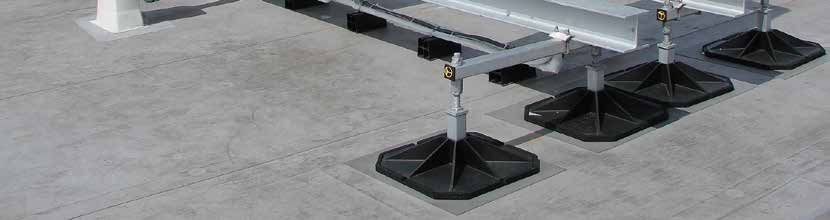
78 Montagesockel & Dachdurchführungen ©Linum
Alixo Foot Framefoot & Zubehör

                            Alixo Framefoot
                            • Zum Aufstellen unter Lüftungskanälen oder Rohrleitungen
                            • Inhalt des Sets ALX-1802: 6 Füße für Profil 41 x 41 mm
                            • Befestigungskit und Profile nicht inklusive

                             Art.-Nr.        Beschreibung                                           Tragkraft pro Füß
                             ALX-1802        H-Rahmenstellfüße Set 305 x 305 mm                          175 kg

                            Optional - Montagekits
                             Art.-Nr.        Beschreibung
                                             Montagekit (optional) für ALX-1802
                             ALX-1908
                                             (2 Winkelstücke + 4 Schrauben M10x25 (mit Scheiben) TVZ + M10 Muttern TVZ)

                            Sendzimir verzinkte Profile aus Stahl
                            • Profile zur Ergänzung (H-Rahmenstellfüße, Konsolen, ...)
                            • Standard-Profile 38 x 40 mm & 41 x 41 mm; ab Lager in Längen
                                                                                                                  ALX-1812
                              von 2 Meter lieferbar                                                               ALX-1813
                            • Endkappe für Profil 41 x 41 mm & 38 x 40 mm aus Kunststoff

                             Art.-Nr.               Abmessungen                 Länge
                             ALX-1812                  38 x 40 x 2              2m
                             ALX-1813                  38 x 40 x 2              3m
                             ALX-1822                  41 x 41 x 2,5            2m                             ALX-1822
                                                                                                               ALX-1823
                             ALX-1823                  41 x 41 x 2,5            3m
                             ALX-9100             Endkappe für Profil 41 x 41
 ALX-9101
                             ALX-9101             Endkappe für Profil 38 x 40

                            Teleskopisch verstellbare Rohrträger
            220-400 mm      •   Material: verzinkter Stahl - Zum Zusammenhalten von isolierten Rohren und Leitungen
                            •   Für Befestigung auf Fix-it Foot oder H-Rahmen (nicht inklusive)
                            •   Gleitmuttern nicht inklusive für Montage auf Fix-it Foot
                            •   Einfache Höhenverstellung (220-400 mm) mittels Rändelschraube
                            •   M8 Stiftschraube zur Befestigung von Rohrhalterungen
                            •   Max. Tragkraft: 80 kg (statisch)

                             Art.-Nr.        Beschreibung
                             ALX-1800        Teleskopisch verstellbarer Rohrträger geeignet für Fix-it Foot
                             ALX-1801        Teleskopisch verstellbarer Rohrträger geeignet für H-Rahmen
ALX-1800        ALX-1801

                            Montage-Anker
                            • Zur einfachen Montage von Konstruktionen wie Solar-Paneele,
                              Klimageräten, Lüftungsanlagen und anderen Installationen auf Flachdächern
                            • Stabile Grundplatte (mit 4 vorgebohrte Locher und Langlöchern), inkl. Gewindestange M10

                             Art.-Nr.        Abm. Fuß           Material     Zugkraft     St/Karton
                             ALX-1960          Ø 196            RVS 316    700 kg/Anker      50

                                                                                                  Alle Abmessungen in mm

©Linum                     Montagesockel & Dachdurchführungen                                                                79
Big Foot Systems - Rahmensysteme
Rahmensysteme
Das ”BIG FOOT”-System ist eine einfache und robuste Konstruktion zur Montage von
BFS-1211 Einheiten auf einem flachen oder leicht geneigtem Dach. Dadurch bleibt das Dach per-
fekt wasserdicht und pflegeleicht. Dies gilt auch für die darauf befindlichen Einheiten,
da jeder Fuß individuell verstellbar und auf Wunsch auch abnehmbar ist.
Die Querverbinder gleiten über die Querstangenlängen, um eine einfache und sichere
Montage zu ermöglichen, ohne dass sich die Schrauben lösen und die Struktur keine
Kräfte mehr als Ganzes aufnimmt.
BFS-1231 Geeignet für alle Anwendungen wie Kondensatoren, Split Außeneinheiten, VRV-
Systeme, Luftbehandlungsgeräte und Selbstkühler.
Merkmale:
• Abmessungen Fuß = 305x305 mm
• Maximale Tragkraft pro Fuß = 185 kg
• Geeignet für alle Dachtypen: Beton, PVC, TPO, Roofing
BFS-1251
• Jeder Fuß ist standardmäßig mit einer integrierten Antivibrationsmatte ausgestattet
• Optionale geneigte Antivibrationsmatten bis zu 5° erhältlich
• Verschiedene Bigfoot-Füße für verschiedene, verstellbare Höhen:
B
290-395 mm (standard), 290-620 mm und 730-825 mm
A
• Standardmodelle mit 1000x1200, 2000x1200 und 3000x1200 mm
in einer Höhe von 290-395 mm
• Glasfaserverstärkte Polyamidfüße für eine perfekte Druckverteilung im Fuß
• Stahlelemente vollständig aus feuerverzinktem Stahl für optimale
Korrosionbeständigkeit und Wetterbeständigkeit (gemäß EN ISO 1461: 1999)
Rahmensysteme
Breite Querstangen
1200 mm 1500 mm
290-395 mm 290-620 mm 730-825 mm 290-395 mm Anzahl
Anzahl Länge Anzahl
(verstellbare (verstellbare (verstellbare (verstellbare Klemmer-
Füße (mm) Verbinders
BFS-1213 Höhe) Höhe) Höhe) Höhe) sets
4 1000 BFS-1211 BFS-1212 BFS-1213 BFS-1511 2 2
4 1500 BFS-1221 BFS-1521 2 2
6 2000 BFS-1231 BFS-1232 BFS-1233 BFS-1531 4 4
1m 6 2500 BFS-1241 BFS-1541 4 4
8 3000 BFS-1251 BFS-1252 BFS-1253 BFS-1551 6 6
8 3500 BFS-1261 BFS-1561 6 6
1.2m MAX : Zubehör Rahmensysteme
1.67m
Art.-Nr. Beschreibung
BFS-9101 Rechte extra Verbinder für Standard Big Foot Rahmen
BFS-1200 Big Foot Querstange 1200 mm
MAX : BFS-1500 Big Foot Querstange 1500 mm
1.25m
BFS-9100 Big Foot extra Klammerset
LAC-501
Jeder fuß ist individuell
verstellbar
BFS-9101 BFS-1200 BFS-9100
80 Montagesockel & Dachdurchführungen ©LinumBig Foot Systems - Rahmensysteme
Rahmensysteme - Maßarbeit
Neben dem Standard-Rahmensystem ist auch eine Maßarbeit möglich:
Big Foot Standard Frames • Höhere FüßeLight
(610Dutybis 825 mm insgesamt)
Frames
• Füße 450 x 450 mm, 600 x 600 mm statt 305 x 305 mm
Non-penetrative support frames for air conditioning mini-splits, VRFs, small AHUs, supply and extract fans
• Andere Querstangenlängen lieferbar
• Optional: schräge Vibrationsmatten (siehe S. 77)
The LD standard product range consists of three standard modular frames, In order to facilitate the process of identifying the required frame for the
available in 1m, 2m and 3m arrangements. This ensures minimal cross- specified air conditioning manufacturers Splits or VRF/VRV units
member deflection whilst maintaining structural stability; as opposed to (or indeed a combination of both) Big Foot Systems have
weaker alternatives often constructed from poor quality pre galvanised strut. created ‘Frame Selectors’. All leading
Maßarbeit? Wir helfen Ihnen !
LightLight
Duty Duty
Frames
LightFrames
Duty Frames VRV/VRF
Our highly competent engineers and designers have developed the product manufacturers
For further details contact the Big Foot Systems
range through our rigorous product development cycle, including validation products
Technical Office on +44 (0)1323 844 355.
covered
VRFs,
mall
HUs,AHUs,
supply
smallsupply
AHUs,
and extract
and
supply
through extract
fans
and extract
testing. fans fans
ames,
order
In to
order
Standard
facilitate
to
In order
facilitate
the to
process
facilitate
the process
ofthe
Frames
identifying
process
of identifying
the
of required
identifying
the required
frame
the required
frame
for theforframe
the for the
PRODUCT INFORMATION
Model
Windberechnungen
1m Modular Frame 2m Modular Frame 3m Modular Frame
s-
pecified
specified
air conditioning
specified
air conditioning
air
manufacturers
conditioning
manufacturers
■ Adjustable leg assemblies
manufacturers
Splits or
Splits
VRF/VRV
or VRF/VRV
Splits
units
or VRF/VRV
units units Part no. B6075 B6077 B6078
or
o indeed
(or indeed
a combination
(oraindeed
combination
aofcombination
both)
■ Feet supplied ofBig
with both)
Foot
Big
of both)
Systems
FootBig
Systems
have
Foot Systems
have have Height (mm) 290-400 290-400 290-400
All leadAll
ingleadingAll leading
Detaillierte Druckberechnungen
reated
d strut.
created
‘Framecreated
‘Frame rubber
Selectors’. mats Selectors’.
Selectors’.
‘Frame Width (mm) 1200 1200 1200
■ 40 x 40 box section frame VRV/VRF VRV/VRFVRV/VRF
roduct manufac man mansufacturers Length (mm) 1000 2000 3000
or further
For further
details
Fordetails
contact
further contact
■ Supplieddetails
the Big
boxed the
contact
Foot
with BigSystems
Foot
the Big
Systems
Foot Systems ufac
turer s turer
dation clamp kits productsproducts products Weight (kg) 40 69 93
echnical
Technical
Office
Technical
Office
on +44 on (0)1323
Office
+44 (0)1323
on
844 +44355.
844
(0)1323
355.844 355.
covered covered covered Max. loading (kg) 480 720 960
RODUCT
PRODUCT
INFORMATION
PRODUCT
INFORMATION
INFORMATION Sichere Arbeitsumgebungen
Model Model Model1m Modular
1m Modular
Frame1mFrame
Modular
2m Modular
2m
Frame
Modular
Frame2mFrame
Modular
3m Modular
3m
Frame
Modular
Frame3mFrame
Modular Frame
Part no.Part no. Part no.
B6075 B6075 B6075
B6077 B6077 B6077
B6078 B6078 B6078
Height (mm)
Height (mm)Height290-400
(mm) 290-400
KIT INCLUDES
290-400
290-400290-400 290-400
290-400290-400 290-400
Technische Beratung bezüglich
Konstruktion & Wahl des Dachtyps
Width (mm)
Width (mm)Width 1200
(mm) 1200 12001200 1200 12001200 1200 1200
40mm x 40mm box section end bars
ength (mm)
Length (mm)Length1000
(mm) 1000 10002000 2000 20003000 3000 3000
1.2m Cross bars – 40 x 40 section
Weight (kg)
Weight (kg) Weight40
(kg) 40 40 69 69 69 93 93 93
Max. loading
Max. (kg)
loading
Max.
305mm Leg assemblies with rubber mats
(kg)loading
480 (kg)
480 480 720 720 720 960 960 960 1 2 3 4
Clamp kits
PROJECT REF: PRODITHERM Material grade: BS EN 10219-1:2006 (S235JR). Welding standard: BS EN ISO 15614-1. Galvanizing standard: BS EN ISO 1461:2009
Reference specification document "Custom Fabrication Specification" (BF-SPEC-050411) for further information
Profile
Assembly instructions 1m / 2 units 2m / 4 units 3m / 6 units
Reference specification document "Big Foot Systems Cross Bar Specification (BF-SPEC-230610) for further information
UNIT REF: CHILLER
40 x 40 mm FOOT PRESSURE: 12.53kN/m2
A UDL: 1.80kN/m2 L
Standard Frame Variants PRODUCT INFORMATION
Model 1m 2m 3m
(4936)
Part no. B9088 B9089 B9090
Height (mm) 290-610 290-610 290-610
Width (mm) 1200 1200 1200
Length (mm) 1000 2000 3000
1m / 2 units
1m / 2 units1m / 2m
2 units
/ 4 units
2m / 4 units2m / 4 units 3m / 6 units
3m / 6 units3m / 6 units
Weight (kg) 40 69 93
Max. loading (kg) 480 720 960
LEG OPTIONS
(2352)
Model Standard Long Stud Large
RODUCT
PRODUCT
INFORMATION
PRODUCT
INFORMATION
INFORMATION
Box section (mm) 40 40 40
Model Model Model
1m 1m 2m 1m2m 3m 2m3m 3m
Min. height (mm) 290 290
B 730
Part no.Part no. Part no.
B9088 B9088
B9089B9088
B9089B9090B9089
B9090 B9090
Max. height (mm) 400 610 825
Height (mm)
Height (mm)Height290-610
(mm) 290-610
290-610
290-610
290-610
290-610
290-610
290-610 290-610
B
Width (mm)
Width (mm)Width1200
(mm) 1200 1200 1200
1200 1200 1200
1200 1200
305/450 ANGLED MATS
ength (mm)
Length (mm)Length
1000
(mm) 1000 2000 1000
2000 3000 2000
3000 3000 2.5° and 5° rubber mats
486 TYP
ADJUSTABLE
SEE TABLE
are also available for
Weight (kg)
Weight (kg) Weight40(kg)
For ease 40 69
of specification 4069 are93
these products 6993 93
detailed on the following building product libraries: sloped roof applications
Max. loading
Max. (kg)
loading
Max.
(kg)loading
480 (kg)
480 720 480
720 960 720
960 960
EG OPTIONS
LEG OPTIONS
LEG OPTIONS Standard Leg Assembly Long Stud Assembly Large Leg Assembly
Model Model Model
Standard
Standard
Long Stud
Standard
LongLarge
Stud Long
Large
Stud Large
4500 TYP
Box section
Box(mm)
sectionBox
(mm)
section
40 (mm)
40 40 4040 40 4040 40
Min. height
Min.(mm)
height Min.
(mm)height
290 (mm)
290 290 290
290 730 290
730 730 4400
Max. height
Max.(mm)
heightMax.
(mm)height
400 (mm)
400 610 400
610 825 610
825 825 1025
C
05/450305/450
ANGLEDANGLED
MATS
305/450MATSANGLED MATS
5° and2.5°
5° rubber
and 5°mats
2.5°
rubber
andmats
5° rubber mats
Vestellbar
ADJUSTABLE
ADJUSTABLE
ADJUSTABLE
ADJUSTABLE
SEE TABLE
SEE TABLE
SEE TABLE
e also are
available
also available
forare also
foravailable for
oped roof
sloped
applications
roof sloped
applications
roof applications
735-840
08/13
StandardStandard
Leg Assembly
Leg Assembly
Standard Long
Leg Stud
Long
AssemblyAssembly
Stud Assembly
LongLarge
Stud Assembly
Leg
Large
Assembly
Leg Assembly
Large Leg Assembly
290-395 mm 290-620
www.bigfootsupport.com
mm
+44 (0)1323 844 355
730-825 mm technical@bigfootsupport.com
sales@bigfootsupport.com @bigfootsystems 19
997 TYP
TITLE:
1:25 DATE: 28/10/2015
Profile
REV
WICHTIG!
Installation and application considerations SCALE:
4.5m x 1.7m W
Euro
should include health, safety and enviromental
D A A3
needs, regulatulations and standards, codes of
50 x 50 mm A SIMMANS practice, climate conditions, installation DRAWN:
Der Kälteanlagenbauer muss prüfen, ob das Flachdach das Gesamtgewicht
location, product orientation, evaluation of the DIMENSIONS IN mm U.O.S DWG No.
& 100 x 50 mm
roof structure, composition, surface and
CHECKED:
J QUINTEL condition, ancillary and complimentary products
aushält und ob die maximale Flächenbelastung nicht überschritten wird!
and materials. Big Foot Systems recommend
that all rooftop products are handled and TOLERANCES: 0.0 ± 0.5mm U.O.S BF4556-001.d
installed by suitably qualified persons. All
scheme designs are based on the use of Big Foot
Systems' products and materials only. THIS
Terms and conditions available on request THE PROPE
SHEET 1 OF 2
08/13
08/13
08/13
1 2 3 4
om
support.com
technical@bigfootsupport.com
technical@bigfootsupport.com
technical@bigfootsupport.com
@bigfootsystems
@bigfootsystems
@bigfootsystems 19 19 19
C
A
A B
©Linum Montagesockel & Dachdurchführungen 81Ihr Servicepartner für :
Big Foot Systems Windberechnungen
Anfrage-Formular Detaillierte Druckberechnungen
Sichere Arbeitsumgebungen
Technische Beratung bezüglich
Konstruktion & Wahl des Dachtyps
Projekt-Kom. : Projektstandort :
Gerät 1 Gerät 2 Gerät 3 Gerät 4 Gerät 5 Gerät 6
GESTELL-NR*
Marke
Typ
Gewicht (KG)
Länge (mm)
Breite (mm)
Höhe (mm)
Platz zwischen
den Geräten
Frequenz
BEMERKUNG : Für genauere Berechnungen bitte das technische Datenblatt des Gerätes mitsenden.
* Verschiedene Geräte auf einem Gestell möglich.
Höhe des Gestells 290 - 395 mm 290 - 620 mm 730 - 825 mm
Spezifische Projekt-
anforderungen
Dachtyp EPDM TPO/PVC Roofing Beton
Dach-Neigungswinkel ° %
Kontaktdaten :
Firma : Telefon :
Branche : E-Mail :
Name : MwSt.-Nr. :
Vorname : Nachricht :
Position :
Adresse :
PLZ :
Ort :
Land :
82 Montagesockel & Dachdurchführungen ©LinumBig Foot Systems - HD Beams & HD Cubes
Heavy Duty Beams
• Unterbau für schwere Installationen (z.B. Kühlsysteme
und Kühlaggregate, Rohre und Verkabelungen)
• Schnelle Montage
• Robust
• Optimale Verteilung des Gewichts
• Feuerverzinkt
• Geeignet für den Innen- und Außenbereich bei
Temperaturen von -40°C bis +80°C
• Set umfasst: 2 Füße, 2 Antivibrationsmatten,
2 Klemmbügel, 1 verstellbare Traverse
• In der Höhe verstellbar
Kontaktieren Sie uns für
infos bezüglich speziellen
Stützbalken (Typ IPE)
Höhenverstelbare HD Beams
• BFS-3301, BFS-3401 & BFS-3601: Höhenverstellbar von 300 bis 360 mm
mit M24 Gewindestange
• BFS-3302, BFS-3402 & BFS-3602: Höhenverstellbar von 300 bis 560 mm
mit M24 Gewindestange
• Ideal für die Verwendung auf leicht schrägen Flächen - Mit Klemmbügeln
Art.-Nr. Abm. Fuß Höhe Tragkraft
BFS-3301 305 x 305 300-360 500 kg
BFS-3302 305 x 305 300-560 500 kg
BFS-3401 450 x 450 300-360 1000 kg
BFS-3402 450 x 450 300-560 1000 kg
Schräge Vibrationsmatten und BFS-3601 600 x 600 300-360 1500 kg
Schutzmatten - siehe S. 77
BFS-3602 600 x 600 300-560 1500 kg
Heavy Duty Cubes
• Unterbau für besonders schwere Installationen
(z.B. große Kühlsysteme und Kühlaggregate,
technische Räume) anhand der “CUBE-METHODE”
• Schnelle Montage
• Robust
• Optimale Verteilung des Gewichtes
• Feuerverzinkt
• Geeignet für den Innen- und Außenbereich bei
Big Foot Price List 2016 Temperaturen von -40°C bis +80°C
• Set umfasst: 4 Füße, 4 Antivibrationsmatten,
feuerverzinkter Stahlrahmen
HD Beams
MODEL PART NO. PRICE
Regelbare HD Cubes
Adjustable 600HD Beam Support with 600mm feet (and clamps) B9373 € 194.25
Adjustable 450HD Beam Support with 450mm feet (and clamps)
• BFS-4401 & BFS-4601: Höhe verstellbar B9423
von 300€ 141.75
bis 360 mm
mit M24 Gewindestange
HD Cubes • BFS-4402 & BFS-4602: Höhe verstellbar von 300 bis 610 mm
MODEL PART NO. PRICE
mit M24 Gewindestange
Adjustable HD Cube 360 - (A) 360mm x (B) 710mm x (C) 800mm + 305mm feet B5611 € 261.63
• Komplett vormontiert
Adjustable HD Cube 560 - (A) 560mm x (B) 710mm x (C) 800mm + 305mm feet B5612 € 318.75
• “Cube” durch 4 Füße unterstützt B5613
Adjustable HD Cube 800 - (A) 800mm x (B) 710mm x (C) 800mm + 305mm feet € 418.05 B C
Adjustable HD Cube 360 - (A) 360mm x (B) 710mm x (C) 800mm + 450mm feet B5614 € 306.14
Art.-Nr. Abm. Fuß Abm. Rahmen
Adjustable HD Cube 560 - (A) 560mm x (B) 710mm x (C) 800mm + 450mm feet B5615
(HxBxT)€ 366.39 Höhe Tragkraft Gewicht
Adjustable HD Cube 800 - (A) 800mm x (B) 710mm x (C) 800mm + 450mm feet B5616 € 423.59
BFS-4401 450 x 450
Adjustable HD Cube 360 - (A) 360mm x (B) 710mm x (C) 800mm + 600mm feet
360 B5617
x 710 x 800 €
300-360 A
367.41
2000 kg 75 kg
BFS-4402
Adjustable HD Cube 560 - (A) 560mm x (B) 710mm x450 x 450
(C) 800mm + 600mm feet 560 B5618
x 710 x 800 € 435.21300-610 2000 kg 75 kg
Schräge Vibrationsmatten und BFS-4601
Adjustable HD Cube 800 - (A) 800mm x (B) 710mm x600 x 600
(C) 800mm + 600mm feet 360 B5619
x 710 x 800 € 510.09
300-360 3000 kg 82 kg
Schutzmatten - siehe S. 77
BFS-4602 600 x 600 560 x 710 x 800 300-610 3000 kg 82 kg
HD Frame Ancillaries
MODEL PART NO. PRICE
Optional - HD Montageplatte
Heavy Duty Mounting Plate B5104 € 71.36
Straight Connectors for 50mm x 50mm Frameworks B6664 € 5.78
• Zur Befestigung von Antivibrationsfedern
Condensing Unit Clamp Kits 50mm x 50mm Systems B6084 € 27.30
• Zur
HD 50mm x 50mm Clamp (each)Verbindung mit den IPE-Trägern
B9306 € 7.35
Condensing Unit Clamp Kits 100mm x 50mm Systems B9181 € 29.40
Art.-Nr. Abmessungen (L x B)
HD Custom Frames
BFS-9300 250 x 200 B5104 B6084
We can provide any size framework for any size project. For design advice contact Big Foot Systems
Alle Abmessungen in mm
Technical Office on +44 (0)1323 844 355... we support you!
©Linum Montagesockel & Dachdurchführungen 832 Safe Access Alixo - Plant Deck Frame 3 4
Material grade: BS EN 10219-1:2006 (S235JR). Welding standard: BS EN ISO 15614-1. Galvanizing standard: BS EN ISO 1461:2009
5 6
Reference specification document "Custom Fabrication Specification" (BF-SPEC-050411) for further information
Reference specification document "Big Foot Systems Cross Bar Specification (BF-SPEC-230610) for further information
Plant Deck Frame
Plant Deck Frame
Part Number
Description
B4040
- Maßarbeit
4 unit
B4060
6 unit
B4080
8 unit A
X 6 10 8
• Entwickelt,
No. of feet
mm
um den2436
Zugriff3436
auf mehrere
4436
VRV/VRF-Installationen zu erleichtern
X Overall Length
POKE • Breite Basis inches bietet zusätzliche
95 14/16 135 4/16 Stabilität
174 10/16 an Orten, an denen viel Wind herrscht
mm 3450 3450 3450
Y • Width
Overall Antirutsch-Gitteroberfläche
1 inches 135 13/16 135 13/16 2 135 13/16 3 4
FRAME
ELINES Z Distance
• Schnelle mm
PROJECT Montage
Between Feet REF: Plant Deck Frame
485 495 500 Material grade: BS EN 10219-1:2006 (S235JR). Welding standard: BS EN ISO 15614-1. Galvanizing standard: BS EN ISO 146
inches 19 2/16 19 8/16 19 11/16 Reference specification document "Custom Fabrication Specification" (BF-SPEC-050411) for further information
• Sicherer
UNIT REF: und
N/A klarer
mm 380
Laufweg380
dank 380
gelber Farbe Reference specification document "Big Foot Systems Cross Bar Specification (BF-SPEC-230610) for further informatio
Min
inches 14 15/16 14 15/16 14 15/16
Y
Height
N/A
FOOT PRESSURE: mm 480 480 480
Max Part Nu
inches 18 14/16 18 14/16 18 14/16
A UDL: N/A Descri
Frame Weight
kg 230 320 410 Y
lbs 507 705 904 No. of
kg 1600 2400 3200 B
Design Load B4040 Kontaktieren
lbs 3527 Sie uns 5291 7055
X Overall Len
für Maßarbeiten
Z Design load based on maximum allowable deflection on cross members when distributed across the bar. Big
Y Overall Wid
Foot's Technical Office is able to analyse deflection and bending stress based on specific load locations and
therefore higher loads may be suitable.
Allowable foot pressure will be subject to roof build-up, typically detailed by a structural engineer. Cross bar
Z Distance Betwe
spacings are adjustable to accomodate various unit sizes.
Working conditions: Suitable for internal or external applications in
temperatures between -40C to +80C Height
X
Frame Weight
B A ( 1:20 ) C Design Load
CANTILEVER STEP
Design load based on maxim
Foot's Technical Office is ab
Material Specification
Z
therefore higher loads may
Density
Part/Description 1
Material Regulation Conformance 2lbs/ft3 3 Allowable foot
4 pressure will
kg/m3 spacings are adjustable to a
PROJECTNylon
Foot REF:GF-30%Plant Deck Frame 1140 71 Material grade: BS EN 10219-1:2006 (S235JR). Welding standard: BS EN ISO 15614-1. Galvanizing standard: BS
Reference specification document "Custom Fabrication Specification" (BF-SPEC-050411) for further inf
mm Mat Rubber BS7188:1989 650-1020 41-64 Working
Reference specification document "Big Foot Systems Cross Bar Specification conditions:for
(BF-SPEC-230610) Suitabl
furthe
SUIT UNIT REF:
Galvanised Steel N/A BS EN ISO1461:1999
Metalwork 7800 487 temperatures between -40
ASTM-A36
CATIONS GRPFOOT
Grating PRESSURE:
GRP N/A BS 4592-6:2008 1500-1700 94-106
A UDL: N/A
TITLE:
Y
380 - 480
Ihr Servicepartner
12/05/2016
für :
DATE:
allation and application considerations REV SCALE: 1:20
include health, safety and enviromental Plant Deck Frame Product Information Sheet
ds, regulations and standards, codes of
A A3 D
actice, climate conditions, installation
S BIRCH DRAWN:
B4060
B4040
n, product orientation, evaluation of the DIMENSIONS IN mm U.O.S DWG No.
X O
C
f structure, composition, surface and
Windberechnungen
CHECKED:
on, ancillary and complimentary products
materials. Big Foot Systems recommend
t all rooftop products are handled and
A SIMMANS
TOLERANCES: 0.0 ± 0.5mm U.O.S BFP-PDF.dwg
talled by suitably qualified persons. All
designs are based on the use of Big Foot
THIS DRAWING IS COPYRIGHT AND
Y O
ystems' products and materials only.
ms and conditions available on request THE PROPERTY OF BIG FOOT SYSTEMS LIMITED
Detaillierte Druckberechnungen
SHEET 1 OF 1
2 3 4 5 6 Z Distan
Part/
Sichere Arbeitsumgebungen
Heigh
Technische Beratung bezüglich
M
Konstruktion & Wahl des Dachtyps
X
Frame
GR
B A ( 1:20 )
Desi
CANTILEVER STEP
A
TIT
Installation and application considerations REV DATE: 12/05/2016 SCALE: 1:20
should include health, safety and enviromental Pl
D
needs, regulations and standards, codes of
practice, climate conditions, installation A DRAWN: S BIRCH A3 load based
Design
location, product orientation, evaluation of the Foot's TechnicalDW
O
B4080 DIMENSIONS IN mm U.O.S
Z
roof structure, composition, surface and
CHECKED: therefore higher lo
condition, ancillary and complimentary products
A SIMMANS
and materials. Big Foot Systems recommend
that all rooftop products are handled and TOLERANCES: 0.0 ± 0.5mm U.O.S BF
Allowable foot pre
Safe Access Alixo - Crossgrip
installed by suitably qualified persons. All spacings are adjus
scheme designs are based on the use of Big Foot
Systems' products and materials only.
Terms and conditions available on request
SHEET 1 OF 2 Working condition
1 2 3 4 temperatures betw
Crossgrip TPO
380 - 480
B4060
• Um Flachdächer (Dachmembranen) vor z.B. herunterfallenden Arbeits- und Wartungs
C
geräten zu schützen
• Anti-Rutsch-Oberfläche (gelbe Farbe) für absolute Sicherheit bei allen Wetterbedingungen
• Stabil bei hohen Windgeschwindigkeiten
• Langlebiges, UV-resistentes Material (flexibles TPO) passt perfekt auf jede Dachstruktur
• Schnelle und einfache Montage:
• Montage ohne Befestigungsmaterialien: kann frei auf der Dachmembrane verlegt werden
• Ausgezeichnete Drainage
• Flexibles Format: Rollen je 10 Meter
Art.-Nr. A Abmessungen (H x B) Material
Installation and application considerations REV
Gewicht
DATE:12/05/2016 Meter/Rolle
SCALE: 1:20
(m)
should include health, safety and enviromental
ALX-1950
D 12 x 600 mm TPO
needs, regulations and standards, codes of
practice, climate conditions, installation A 5,2 kg/m²
DRAWN:S BIRCH 10 A3
location, product orientation, evaluation of the
B4080 roof structure, composition, surface and
CHECKED:
DIMENSIONS IN mm U.O.S
condition, ancillary and complimentary products
A SIMMANS
Kontaktieren Sie uns and materials. Big Foot Systems recommend
that all rooftop products are handled and TOLERANCES: 0.0 ± 0.5mm U.O.S
für Maßarbeiten
installed by suitably qualified persons. All
scheme designs are based on the use of Big Foot
Systems' products and materials only.
Terms and conditions available on request
SHEET 1 OF 2
1 2 3 4
84 Montagesockel & Dachdurchführungen ©LinumSafe Access Alixo - Step Over
Step Over
• Speziell zur Einrichtung sicherer Laufanlagen für Service-Techniker entwickelt
• Material: feuerverzinkt galvanisierter Stahl
• Solide Konstruktion
• Freistehend auf dem Dach (keine Perforierungen der Dachhaut)
• Standard mit 1, 2, 3 oder 4 Stufen erhältlich
Art.-Nr. Beschreibung Stellfüß (mm) Höhe (mm) Plattform (mm)
ALX-0001 1 Stufe Step Over 305 x 305 +/- 265 1000 x 1000
ALX-0002 2 Stufen Step Over 305 x 305 +/- 530 1000 x 1000
Strut
ALX-0003 3 Stufen Step Over 305 x 305 +/- 730 1000 x 1000
ALX-0004 4 Stufen Step Over 305 x 305 +/- 875 1000 x 1000
StepOvers
utFoot offer a full range of StepOvers to their cusomers. Each StepOver is complete with
00mm wide steps, 1000x1000mm platfrom and the handrail.
th our in house design and manufacturing, StrutFoot can supply and install bespoke
ccess to meet the customers specification.
Kontaktieren
e framework on all of our access Sie
is HDG ensuring it is uns
suitable for roof applications. All of
für Maßarbeiten
e leg assemblies supplied are adjustable and supplied with our R305 plastic feet.
of the below systems are available from stock and easily installed.
1 Stufe
StrutFoot StepOvers
Feet Size Platform Size
Part No. Description
(mm) (mm)
SF8010 SFA111 - 1 Step StepOver 305 1000x1000
Big Foot Systems - Louvre Screen Support
SF8020 SFA212 - 2 Step StepOver 305 1000x1000
SF8030 SFA313 - 3 Step StepOver 305 1000x1000
SF8040 SFA414 - 4 Step StepOver 305 1000x1000
StrutFoot Platform
Louvre Screen Support - Maßarbeit
Part No. Description
Feet Size Platform Size • Entworfen, um Installationen auf Dächern abzuschirmen (visueller Aspekt).
(mm) (mm)
Wird häufig in städtischen Gebieten eingesetzt, in denen Installationen leicht
SF8050 SFA555 - StrutFoot Platform 305 1000x1000
von Gebäuden in der Umgebung zu sehen sind
StrutFoot Ltd, Alma Street, Wednesbury, West Midlands, WS10 0QB. • Dämpft das Geräusch von Installationen auf Dächern (akustischer Aspekt)
E-mail: sales@strutfoot.co.uk Phone: 01922 650174 Fax: 01922 614969
• Schnelle Montage
• Innovatives Design
• Robust
• Maßarbeit
• In Kombination mit “HD Beams" verwendbar (siehe Seite 83).
Dies bietet folgende Vorteile:
- Höhenverstellbar
- Maßarbeit (d.h. geeignet für verschiedene Höhen und Neigungswinkel)
- Perfekte Stabilität
Kontaktieren Sie uns
für Maßarbeiten
1 2 3 4 5 6 7 8 9 10 11 12 13 14 15 16
PROJECT REF: Material grade: BS EN 10219-1:2006 (S235JR). Welding standard: BS EN ISO 15614-1. Galvanizing standard: BS EN ISO 1461:2009
Reference specification document "Custom Fabrication Specification" (BF-SPEC-050411) for further information
UNIT REF: Reference specification document "Big Foot Systems Cross Bar Specification (BF-SPEC-230610) for further information
A A
FOOT PRESSURE:
UDL:
B B
C C
D D
E E
F F
G G
H H
I I
J J
K K
TITLE:
REV DATE: 15/11/2018 SCALE: 1 : 15
A0
Installation and application considerations
should include health, safety and enviromental
needs, regulatulations and standards, codes of
practice, climate conditions, installation DRAWN: Emmanuel
DWG No.
location, product orientation, evaluation of the DIMENSIONS IN mm U.O.S
15-11-18 - Louvre + Access Assembly.dwg
roof structure, composition, surface and
condition, ancillary and complimentary products CHECKED:
and materials. Big Foot Systems recommend
L that all rooftop products are handled and
installed by suitably qualified persons. All
TOLERANCES: 0.0 ± 0.5mm U.O.S L
scheme designs are based on the use of Big Foot THIS DRAWING IS COPYWRIGHT AND
Systems' products and materials only.
Terms and conditions available on request SHEET 2 OF 3 THE PROPERTY OF BIG FOOT SYSTEMS LIMITED
1 2 3 4 5 6 7 8 9 10 11 12 13 14 15 16
©Linum Montagesockel & Dachdurchführungen 85Big Foot Systems - Zubehör
Plattformen
• Für Big Foot-Füße
• Verfügbar mit flacher Plattform oder mit 2 oder 4 Seiten
• Mit Gewinde (M10) in der Mitte der Plattform
• Set umfaßt: 2 Füße, 2 Antivibrationsmatten und 2 Plattformen
Art.-Nr. Abm. Fuß Typ Plattforme Tragkraft
BFS-9430 305 x 305 Flach 150 kg
BFS-9432 305 x 305 2 Seiten 150 kg
BFS-9434 305 x 305 4 Seiten 150 kg
BFS-9440 450 x 450 Flach 250 kg
BFS-9442 450 x 450 2 Seiten 250 kg
BFS-9444 450 x 450 4 Seiten 250 kg
Flach 2 Seiten 4 Seiten
Vibro-Matten
• Schützen die Dachmembran vor Schäden
• Material: recycelter Kautschuk
• Verschiedene Formate verfügbar: klein, groß, Fliese, Streifen
Art.-Nr. Abmessungen
LAV-6612 600 x 150 x 30
LAV-6952 1000 x 500 x 30
LAV-6443 400 x 400 x 36
LAV-6554 500 x 500 x 45
LAV-6901 1000 x 75 x 15
LAV-6920 1000 x 125 x 8
Schutzmatte
• Schutz für PVC-Dächer
Art.-Nr. Abm. Fuß Material
ALX-1951 650 x 650 TPO
Geprägter Gleitschutz aus Kautschuk Antivibrations-Pads
• Vibrationsunterlage aus Kautschuk
• Öl-resistent
• Vibrationsdämpfend
• Mögliche Belastbarkeit: bis 345 kN pro m²
• Ideal für Klimaanlagen, Kühltürme, Kompressoren, ...
Art.-Nr. Länge Breite Höhe Gewicht (g) Tragkraft max.* (kg)
LAV-5102 51 51 22,2 50 ± 90
LAV-5202 76 76 22,2 100 ± 200
LAV-5302 101 101 22,2 200 ± 352
LAV-5402 152 152 22,2 400 ± 800
LAV-5502 305 305 22,2 1650 ± 3200
Vibrationsdämpfendes Material aus Neopren
LAV-5602 457 457 22,2 3400 ± 7200
*: Hinweis: die Belastung ist immer durch den Benutzer zu testen, unter Berücksichtigung
der Gegebenheiten.
Alle Abmessungen in mm
86 Montagesockel & Dachdurchführungen ©Linum©Linum Montagesockel & Dachdurchführungen 87
Aluminium-Dachdurchführungen

                                    Standard Aluminium-Dachdurchführung
                                    • Kabel- & Leitungsdurchführung für Flachdächer
                                    • ALX-7126/ALX-7156 besitzen einen patentierten Flansch als zusätzlichen Schutz vor
                                      tropfendem Wasser zwischen Dachdurchführung und Dachmembrane
                                    • Große Montagefläche für einen sicheren Anschluss an die Dachmembrane
                                    • Regensicher
                                    • Abgerundeter Auslass unter der Kappe schützt die Kabel und den Isolationsmantel
       H1                           • Einfache Montage
                                    • Inklusive Edelstahl-Schrauben
                                    • Für jeden flachen Dachtyp geeignet

                                     Art.-Nr.                 Öffnung               Höhe   Höhe H1     Basis
                     ALX-7156        ALX-7102                 80 x 80               275      155     255 x 255
                                     ALX-7122                 125 x 125             275      155     340 x 340
                                     ALX-7126                 125 x 125             600     400      425 x 425
                 Basis mit           ALX-7156                250 x 125              600     400      550 x 550
            abgerundeten Ecken
                                     ALX-7446                200 x 200              600     400      500 x 500

                                    *: ALX-7446 hat 2 Auslässe

                        ALX-7102                                    ALX-7126                               ALX-7446

                                                             Patentierter Flansch

                                                             Dachmembran

                     ALX-7122                   Patentiert

                                                                                                     Alle Abmessungen in mm

88                                 Montagesockel & Dachdurchführungen                                             ©Linum
Aluminium-Dachdurchführungen
Aluminium-Dachdurchführung - spezielle Ausführungen
• Kabel- & Leitungsdurchführung für Flachdächer
• Große Montagefläche für einen sicheren Anschluss an die Dachmembrane
• Regensicher
• Abgerundeter Auslass unter der Kappe schützt die Kabel und den Isolationsmantel
• Einfache Montage
• Für jeden flachen Dachtyp geeignet
H1
Art.-Nr. Öffnung Höhe Höhe H1 Basis
ALX-7175 400 x 400 575 300 550 x 550
ALX-7186 500 x 200 600 400 680 x 425
ALX-7169 300 x 200 900 700 480 x 425
ALX-7175 ALX-7186 ALX-7169
Spezieller gerader Extra breiter Extra hoher
Auslass Auslass Auslass
Alle Abmessungen in mm
©Linum Montagesockel & Dachdurchführungen 89Aluminium-Dachdurchführungen
Aluminium-Dachdurchführungen mit verstellbarem Unterbau
• Kabel- & Leitungsdurchführung für Flachdächer
• Dachdurchführung kombiniert mit Aluminium-Unterbau
• Ideal für Neubau- oder Isolationsprojekte
• Aluminium-Unterbau passend zur Aluminium-Dachdurchführung
• Die Höhe ist exakt einstellbar je nach Isolationsstärke (bis max. 300 oder 350 mm)
• Regensicher
• Für jeden flachen Dachtyp geeignet
Art.-Nr. Öffnung Höhe Unterbau Höhe Höhe H1
Dachdurchführung Dachdurchführung
ALX-7100 80 x 80 250 275 155
ALX-7120 125 x 125 350 600 400
ALX-7150 250 x 125 350 600 400
+ +
H1 H1
H1
+
ALX-7102 ALX-7126 ALX-7156
Kit ALX-7100 = Kit ALX-7120 = Kit ALX-7150 =
ALX-7102 + Unterbau ALX-7126 + Unterbau ALX-7156 + Unterbau
SHEET 2 OF 2 SCALE:1:5 SCALE:1:5 SHEET 2 OF 2
AlMgSi0.5 514.475
C
D
A
514.475 AlMgSi0.5
B
E
F
A4
DWG NO.
A4
Q.A MATERIAL:
DWG NO.
MATERIAL: Q.A
MFG
Aluminium-Wanddurchführungen
MFG
Ansamblu
A4
APPV'D Liban Eeckhout
AATEQ
Liban Eeckhout APPV'D
CHK'D Ansamblu E
F
Gabriel Oancea AATEQ Gabriel Oancea CHK'D
DRAWN Catalin F. Catalin F. DRAWN
TITLE:
Client: LINUM
NAME SIGNATURE DATE TITLE: DATE SIGNATURE NAME
ANGULAR:
Nr. bucati: Client: LINUM ANGULAR:
REVISION
Nr. bucati:
1
1
LINEAR: LINEAR:
C
D
AnsambluA
TOLERANCES:
B
E
F
TOLERANCES:
SURFACE FINISH:
DIMENSIONS ARE IN MILLIMETERS Data: 30.03.2020 EDGES
BREAK SHARP
EDGES
Data: 30.03.2020 SURFACE FINISH:
SHEET 1 OF 1
DO NOT SCALE DRAWING REVISION
BREAK SHARP DIMENSIONS ARE IN MILLIMETERS
REVISION
UNLESS OTHERWISE SPECIFIED: FINISH: DEBUR AND
DO NOT SCALE DRAWING
DEBUR AND FINISH: UNLESS OTHERWISE SPECIFIED:
• Wanddurchführung für Kabel
A4
1
519.053
C
D
519.053 A4 A
B
• Abgerundeter Auslass unter der Kappe schützt die Kabel und den Isolationsmantel
E
F
D
E
F
• Einfache Montage mit vorgebohrte Locher
REVISION
1
1
DO NOT SCALE DRAWING
Ansamblu
E
- ALX-7711: 4x Ø4 mm
F
SHEET 1 OF 1
- ALX-7731:
4 6x Ø4 mm
2.00
REVISION
1
1
F
Ansamblu
1
SHEET 1 OF 1
2
2
102
C
201
A
D
100
001
B
E
F
4Art.-Nr.
DO NOT SCALE DRAWING
2.00
F Wandöffnung Durchlass unten Höhe Befestigungsplatte
APPV'D
TOLERANCES:TOLERANCES:
SURFACE FINISH:
DIMENSIONS ARE
UNLESS OTHERWISE
DRAWN
CHK'D
519.053
MFG
2 1
Q.A
LINEAR:
ANGULAR: ANGULAR:
DWG NO.
SCALE:1:5
C
A
D
B
APPV'D
TOLERANCES:
SURFACE FINISH:
DIMENSIONS ARE IN MILLIMETERS
UNLESS OTHERWISE SPECIFIED:
DRAWN
CHK'D
MFG
ALX-7711 125 x 100 100 x 100 170 140 x 170
Q.A
TITLE:
ANGULAR:
LINEAR:
C
C
A
D
D
C
A
D
B
B
E
E
F
F
B
E
F
Gabriel
Costea
Liban
Gabriel Oancea
Costea Valentin
Liban Eeckhout
00
2.00
APPV'D
D'VPPA
SURFACE FINISH:
DIMENSIONS
UNLESSSPECIFIED:
:DEIFICEPS ESIWREHTO SSELNU
SRETEMILLIM NI ERA SNOISNEMID
:HSINIF ECAFRUS
:SECNARELOT
DRAWN
NWARD
APPV'D
TOLERANCES:
SURFACE FINISH:
DIMENSIONS
UNLESS OTHERWISE SPECIFIED:
CHK'D
DO NOT SCALE DRAWING
D'KHC
DRAWN
MFG
CHK'D
NAME
ALX-7731
MFG
200 x 150 150 x 150 170 225 x 200
Q.A
3
Q.A
NAME
LINEAR:
:RAENIL
:RALUGNA
LINEAR:
ANGULAR:
Eeckhout
4.
4
200.00
Oancea
Valentin
IN MILLIMETERS
BREAK SHARP
DEBURR AND
4
4
200.00
2
2
150.00
OTHERWISE SPECIFIED:
Gabriel Oancea
aecnaO leirbaG
146.00
Gabriel Oancea
Costea
nitnelaV aetsoC
SIGNATURE
Liban Eeckhout
6x
tuohkceE nabiL
12
Costea Valentin
Liban Eeckhout
SCALE:1:5 SHEET 2 OF 2
TITLE: EDGES
AlMgSi0.5 514.475 3
FINISH:
ALX-7711 ALX-7731 E
ARE IN MILLIMETERS
0.
ARE Valentin
150.00
2.00
DWG NO.
NAME
SCALE:1:5
EMAN
NAME
A4
00
DWG NO.
25.00
Q.A
IN MILLIMETERS
MATERIAL:
SIGNATURE SIGNATURE
2.00
120.00 80.00
4
4
4
200.00 00200.00
.002
DATE
4
4
MFG
Ansamblu 12
2
2
APPV'D Liban Eeckhout
AATEQ
FINISH:
E
225.00
0. 80
WEIGHT:
MATERIAL:
88
CHK'D Gabriel Oancea
00
2
00
DRAWN Catalin F.
.0 150.00 00150.00
.051
2.00
3
6.
4.
TITLE:
Client: LINUM
NAME SIGNATURE DATE
140.00 Nr. bucati: 0
8 NO.
SCALE:1:5
BREAK SHARP
ERUTANGIS
DEBURR AND
80.00
ANGULAR:
SIGNATURE
225.00
15
140
25.00 25.00
LINEAR:
80 2
3
3
100.00
TOLERANCES:
8DWG
146.00140
TITLE:
MATERIAL:
2
SURFACE FINISH:
Data: 30.03.2020
6x
EDGES
FINISH:
:HSINIF
FINISH:
DATE
100
DIMENSIONS ARE IN MILLIMETERS BREAK SHARP
120.00120.00
WEIGHT:
.0
DO NOT SCALE DRAWING REVISION
EDGES
UNLESS OTHERWISE SPECIFIED: FINISH: DEBUR AND
EDGES
BREAK SHARP
DEBURR AND
100
146.00
156.8
0
25.00 0
6.
6x
0
00
4.225.00225.00
15
2
120.00 80.00
°
WEIGHT:
MATERIAL:
4.
00.52
BREAK SHARP
25.00
3
DEBURR AND
00
00
4.
51.
51.
DWG NO.
SCALE:1:5
TITLE:
DATE
DATE
ETAD
DATE
00°
88
156.8
00.021
51. 146.00
120.00
6x
120.00
8
00°
EDGES
3
3
D
146.00
6.
15
6x
DO NOT SCALE DRAWING
2
00.522
225.00
225.00
0 15
170.00
WEIGHT:
MATERIAL:
WEIGHT:
MATERIAL:
6Ansamblu
80.00
3
3
15 1.20502. 80.00
519.053
.8
MATERIAL:
FINISH:
SIGNATURE
8
WEIGHT:
1
80.00
8
D
88
001 00200011.0
3
3
3
3
3 80.00
170
071
51
15
15
080
15 0
8
6.
150.00
.0
25.00
0
DIMENSIONS ARE IN MILLIMETERS
.6
680.00
EDGES
BREAK SHARPBREAK SHARP
DEBURR AND DEBURR AND
6.
00.08
225.00
80.00
1
56.
50
.8
SHEET 1 OF 1
UNLESS OTHERWISE SPECIFIED:
146.00
3
3
DATE
88
88
MATERIAL:
225.00
115
6x
8
200.00
DRAWN Costea Valentin
CHK'D Gabriel Oancea
WEIGHT:
88
Liban Eeckhout
3
REVISION
120.00 0
4
4
20
ALX-7711 ALX-7731
1
6.
NAME
120.00
0.
4.
EDGES
DNA RRUBED
PRAHS KAERB
SEGDE
EDGES
BREAK SHARP
DEBURR AND
15
25.00
FINISH:
SIGNATURE
146.00
00.641
00
FINISH:
146.00
4 3
A4
TOLERANCES:
DATE
6x
x6
25.00
6x
D Gabriel Oancea ANGULAR:
DWG NO.
SCALE:1:5
TITLE:
120.00
Alle Abmessungen in mm
C
A
D
N Costea Valentin LINEAR:
SURFACE
B
C
150.00
F
APPV'D
NSIONS ARE IN MILLIMETERS
4.
.4
4.
MFG
Q.A
SS OTHERWISE SPECIFIED:
0
00
00
25 2.
FINISH:
SIGNATURE
0
200.00
'D Liban Eeckhout
C
.0 00
D
A
DWG NO.
SCALE:1:5
TITLE:
:ELTIT
B
DO NOT SCALE
E
DWG NO.
F
SCALE:1:5
TITLE:
C
2
2
140
0 F
4
4
0
2.00 2.
NAME
0
100 150.00
90 25 Montagesockel & Dachdurchführungen ©Linum
6.
2.
ILLIMETERS
519
An
CE FINISH:
22 150.00
014
.0 0
PECIFIED:
ANCES:
5. 0
GULAR:
0
E
F
DODRA
ON OD
51.0 200.00
DO NO
lentin
ncea
2
2
2
hout
2
2
.0
AR:
0°
.2
2.
NO
200.00Sie können auch lesen