The RLC-Box "Standard" and "Deluxe" - AK-Modul ...
←
→
Transkription von Seiteninhalten
Wenn Ihr Browser die Seite nicht korrekt rendert, bitte, lesen Sie den Inhalt der Seite unten
Manual for the RLC-Box "Standard" and "Deluxe"

With one of these RLC-Boxes you can quickly select a value out of 48 resistors, 48
capacitors and 44 inductors in a range of up to 6 decades.
The "Deluxe"-version additionally lets you fine-tune the resistance value from 1Ω to
100kΩ with two 10-turn potentiometers with an analog turning knob with a dial for
10 revolutions and 50 divisions per revolution. There you also get a sheet with the
measured values of all capacitances and inductances.
The highlight is that you can not only use each of the 3 components (L/R/C)
individually at the binding posts, but with the help of only 2 additional toggle-
switches you can connect the 3 components in a multitude of serial and parallel
combinations.
Thereby you can create RC- and LC-series or parallel connections, 1st ans 2nd order
high-pass and low-pass filters, band-pass and band-stop filters, RLC-series and
parallel tank-circuits etc.
The necessary switch-settings and input, common and output terminals can be read
off 4 labels on the sides of the box (or from this manual).

                   © 2020 by Roger Leifert, AK-Modul-Bus, KainkaLabs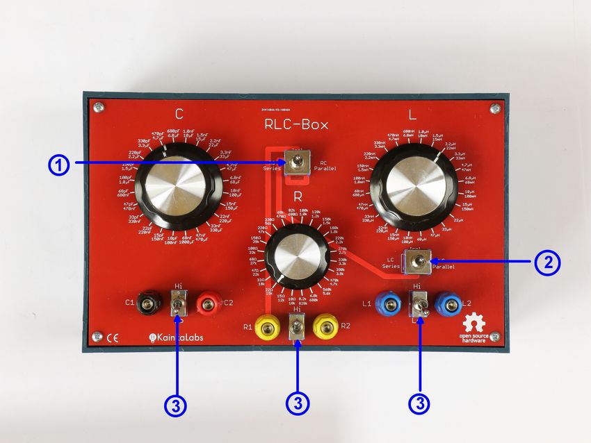
RLC-Box Standard-Version

(1) Toggle-Switch (DPDT On-None-On) for R+C in parallel, R+C in series or
   mutually isolated

(2) Toggle-Switch (DPDT On-None-On) for L+C in parallel, L+C in series or
   mutually isolated

(3) Toggle-Switch (SPDT) for upper and lower range of the 24-position rotary
    switches for L, R, C
    R(low) = 10Ω - 8.2kΩ (10Ω - 1kΩ E6-stepping; else: E12-stepping)
    R(high) = 10kΩ - 820kΩ (E12-stepping)
    C(low) = 10pF - 68nF      (E6-stepping)
    C(high) = 100nF - 1000µF (E6-stepping)
    L(low) = 10nH - 68µH (E6-stepping)
    L(high) = 100µH - 150mH (E6-stepping)

               © 2020 by Roger Leifert, AK-Modul-Bus, KainkaLabs
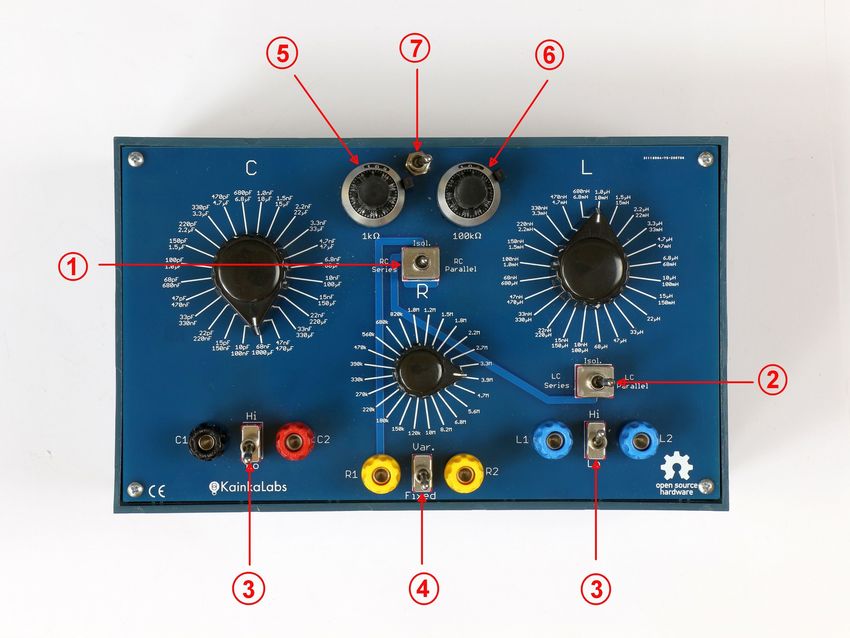
RLC-Box Deluxe-Version

(1) Toggle-Switch (DPDT On-None-On) for R+C in parallel, R+C in series or
    mutually isolated
(2) Toggle-Switch (DPDT On-None-On) for L+C in parallel, L+C in series or
    mutually isolated

(3) Toggle-Switch (SPDT) for upper and lower range of the 24-position rotary
    switches for L, C. (Ranges as in Standard-Version)
(4) Toggle-Switch (SPDT) for fixed (24-position rotary switch) and variable
    range (2x10-turn pots) for R: 120kΩ-10MΩ in E12-Stepping

(5) 1kΩ 10-turn potentiometer with analog turning knob with dial for 10
    revolutions and 50 divisions per revolution
(6) 100kΩ 10-turn potentiometer with analog turning knob with dial for 10
    revolutions and 50 divisions per revolution
(7) Toggle-Switch (SPDT) for selecting 1kΩ or 100kΩ potentiometer

     The turning knobs for the potentiometers have a locking-lever.
            Do not to try to turn the knob while it is locked!

               © 2020 by Roger Leifert, AK-Modul-Bus, KainkaLabs
Technical data:
• Fixed Resistors:
◦ SMD12
◦ 1% tolerance
◦ =50VDC voltage rating
• 10-turn potentiometers:
◦ 5% tolerance of nominal value
◦ 0,25% linearity
◦ =50VDC voltage rating
• Capacitors:
◦ >=50VDC/30VAC voltage rating
◦ 10pF...68nF: SMD1206 COG/NP0 ceramic capacitors 5% tolerance
◦ 100nF...1µF: Polypropylene plastic film capacitors 5%/10% tolerance
◦ 1.5µF...10µF: PET plastic film capacitors 5%/10% tolerance
◦ 15µF...1000µF: Aluminum electrolytic capacitors; 10%/20% tolerance
◦ parasitic parallel capacitance: ca. 10...20 pF
• Inductors:
◦ 10nH-680nH: SMD1210; Fastron AS1210
◦ 1µH...150mH: (mostly) cylindrical Fastron inductors
◦ parasitic series inductance: 100...250 nH
◦ tolerance 5%/10%/20%
◦ current rating: see table
• Size: 215x110x130 mm
• Weight: 680g (Standard) / 730g (Deluxe)
© 2020 by Roger Leifert, AK-Modul-Bus, KainkaLabsRC- LC- Common Eckfrequenz/
# Typ Eingang Ausgang Güte
Schalter Schalter GND Resonanzfrequ.
1. R (isoliert) Independent Independent R1+R2
2. L (isoliert) Independent Independent L1+L2
3. C (isoliert) Independent Independent C1+C2
4. RC-Parallelschaltung Parallel Independent R2/C2 R1/C1
5. RC-Reihenschaltung Series Independent R1 C1
6. LC Paralell-Schwingkreis Independent Parallel C2/L1 C1/L2 1/(2*π*SQRT(L*C))
7. LC Reihen-Schwingkreis Independent Series C2 L1 1/(2*π*SQRT(L*C))
8. RC Tiefpass (6dB/Oct.) Series Independent R1 C1 R2/C2 1/(2*π*R*C)
9. RC Hochpass (6dB/Oct.) Series Independent C1 R2/C2 C2 1/(2*π*R*C)
10. RLC Low-pass (12dB/Oct.) Series Independent R1 C1 R2/C2 1/(2*π*R*C)
11. RLC High-pass (12dB/Oct.) Series Independent C1 R2/C2 C2 1/(2*π*R*C)
12. RLC SeriesBand-pass Series Series L1 R1 R2/C2 1/(2*π*SQRT(L*C)) 1/R*SQRT(L/C)
13. RLC Series Band-stop Series Series R1 L1 R2/C2 1/(2*π*SQRT(L*C)) 1/R*SQRT(L/C)
14. RLC Parallel Band-pass Series Series R1 C1/L2 C2/R2/L1
15. RLC Parallel Band-stop Series Series C1/L2 R1 C2/R2/L1
16. RLC Series Tank-Circuit Series Series R1 L1 1/(2*π*SQRT(L*C)) 1/R*SQRT(L/C)
17. RLC Parallel Tank-Circuit Parallel Parallel R2/C2/L1 R1/C1/L2 1/(2*π*SQRT(L*C))
Funktionen, Schalterstellung, Klemmenbelegung, Eck-/Resonanzfrequenz, Güte
In obiger Tabelle sind die Schalterstellungen und die Anschlussklemmen-Belegung
für die verschiedenen Funktionen zusammen mit einigen Kenndaten aufgelistet.
Die ersten 3 Einträge sind für die isolierte Verwendung der Bauteile:
1. Einstellung für isolierte Verwendung von R
2. Einstellung für isolierte Verwendung von L
3. Einstellung für isolierte Verwendung von C
Es folgen die Zusammenschaltung von Widerstand und Kondensator zu einer
Reihen- oder Parallel-Schaltung. Die Reihenschaltung wird z.B. als sog.
"Snubber" (auch "Boucherot-" bzw. "Zobel-Glied") eingesetzt:
4. RC-Parallelschaltung
5. RC-Serienschaltung
Das gleiche für die Zusammenschaltung von Kondensator und Induktivität zu
einem Reihen- oder Parallel-Schwingkreis.
Die Dämpfung wird hier im Wesentlichen durch den internen Serienwiderstand
der Induktivität begrenzt:
6. LC-Parallelschaltung
7. LC-Serienschaltung
© 2020 by Roger Leifert, AK-Modul-Bus, KainkaLabsAuf den nächsten Seiten folgen die Filterschaltungen und Schwingkreise, die auch
auf den Aufklebern der RLC-Box dargestellt sind.
Ein Kondensator ist immer als Elko dargestellt, um die Lage der Anode bei
Kapazitäten über 10µF (=rote Polklemme) in der Schaltung anzuzeigen.
Für die Spule wurde das alte/amerikanische Symbol verwendet, um die "Lesbarkeit"
für den englischsprachigen Raum zu verbessern bzw. um Verwechselungen zu
vermeiden.
Die Schalterstellung der beiden Kippschalter ist auf dem Bild jeweils rechts unten
dargestellt.
Die Anschlussbuchsen (z.B. "R1") für Ein-/Ausgang und der gemeinsame Anschluss
der Schaltung (=Common/Ground/Masse) sind an den entsprechenden Anschlüssen
eingezeichnet.
Wenn ein Anschluss parallel an mehreren Buchsen gleichzeitig anliegt, sind diese
durch einen Schrägstrich getrennt (z.B. "R2/C2")
Beispiel für ein Schaltbild mit Schalterstellung und Anschlussklemmen-Bezeichnungen
© 2020 by Roger Leifert, AK-Modul-Bus, KainkaLabs8. RC-Tiefpass 1.Ordnung (6dB/Oktave = 20dB/Dekade)
Das Bild zeigt den klassischen RC-Tiefpass 1. Ordnung mit 6dB/Oktave Steilheit.
1
3dB-Grenzfrequenz: f g =
2 π RC
1
Amplitude linear: A=
√ 1+(2 π f RC )2
1
Amplitude in dB: A=20∗log ( )
√ 1+(2 π f RC)2
Phasenverschiebung: ϕ =−arctan (2 π f RC )
Zeitkonstante (bei Verwendung als RC-Zeitglied): τ =RC
Die Einstellzeit bei Verwendung als RC-Zeitglied:
τ 2,3τ 4,6τ 6,9τ
37% 10% 1% 0,1%
© 2020 by Roger Leifert, AK-Modul-Bus, KainkaLabs9. RC-Hochpass 1.Ordnung (6dB/Oktave = 20dB/Dekade)
Das Bild zeigt den klassischen RC-Hochpass 1. Ordnung mit 6dB/Oktave Steilheit.
1
3dB-Grenzfrequenz: f g =
2 π RC
1
Amplitude linear: A=
√ 1+(1/(2 π f RC ))2
1
Amplitude in dB: A=20∗log ( )
√ 1+(1/(2 π f RC ))2
Phasenverschiebung: ϕ =arctan (1/(2 π f RC ))
© 2020 by Roger Leifert, AK-Modul-Bus, KainkaLabs10. RLC-Tiefpass 2.Ordnung (12dB/Oktave = 40dB/Dekade)
Das Bild zeigt eine Möglichkeit einen RLC-Tiefpass 2. Ordnung mit 12dB/Oktave
Steilheit zu realisieren.
Hier muss ausnahmsweise eine zusätzliche Verbindung zwischen den Klemmen
L2 und R1 hergestellt werden!
3dB-Grenzfrequenz:
Amplitude linear:
Amplitude in dB:
Phasenverschiebung:
© 2020 by Roger Leifert, AK-Modul-Bus, KainkaLabs© 2020 by Roger Leifert, AK-Modul-Bus, KainkaLabs
11. RLC-Hochpass 2.Ordnung (12dB/Oktave = 40dB/Dekade)

Das Bild zeigt eine Möglichkeit einen RLC-Hochpass 2. Ordnung mit 12dB/Oktave
Steilheit zu realisieren.

3dB-Grenzfrequenz:

Amplitude linear:

Amplitude in dB:

Phasenverschiebung:

                    © 2020 by Roger Leifert, AK-Modul-Bus, KainkaLabs
12. RLC-Bandpass (Variante 1)
Das Bild zeigt eine Möglichkeit für einen RLC-Bandpass
© 2020 by Roger Leifert, AK-Modul-Bus, KainkaLabs13. RLC-Bandsperre (Variante 1)
Das Bild zeigt eine Möglichkeit für eine RLC-Bandsperre
© 2020 by Roger Leifert, AK-Modul-Bus, KainkaLabs14. RLC-Bandpass (Variante 2)
Das Bild zeigt eine Möglichkeit für einen RLC-Bandpass
© 2020 by Roger Leifert, AK-Modul-Bus, KainkaLabs15. RLC-Bandsperre (Variante 2)
Das Bild zeigt eine Möglichkeit für eine RLC-Bandsperre
© 2020 by Roger Leifert, AK-Modul-Bus, KainkaLabs16. RLC-Serienschwingkreis
Das Bild zeigt einen (durch R1) gedämpften Serienschwingkreis.
© 2020 by Roger Leifert, AK-Modul-Bus, KainkaLabs17. RLC-Parallelschwingkreis
Das Bild zeigt einen (durch R1) gedämpften Parallelschwingkreis.
© 2020 by Roger Leifert, AK-Modul-Bus, KainkaLabsTechnical Data of the used components Actual types & specifications may vary due to availability! © 2020 by Roger Leifert, AK-Modul-Bus, KainkaLabs
Circuit-Diagrams of the "Standard" and "Deluxe" Model

        © 2020 by Roger Leifert, AK-Modul-Bus, KainkaLabs
Inside the prototype of the "Deluxe" Version
The PCBs for the inductors and capacitors are "double-stacked" and soldered directly
to the rotary switch contacts.
You also can see the two blue 10-turn precision potentiometers.
(In the standard version the rotary switch for the resistors also has double-stacked
PCBs)
© 2020 by Roger Leifert, AK-Modul-Bus, KainkaLabsThe "original" RLC-Box build around 2005 for personal use
© 2020 by Roger Leifert, AK-Modul-Bus, KainkaLabsAdhesive labels for the sides of the RLC-box (for custom cutout)
© 2020 by Roger Leifert, AK-Modul-Bus, KainkaLabsProtocol of the measured L- and C-values of the first prototype
You can see from the data that the parasitic parallel capacitance is around 15 pF and the paratic
series inductance is around 100...150 nH.
The first decade of the inductances is therefore of no good use und will be left out in later version.
Nevertheless the relatively low parasitic capacitance and inductance makes the RLC-Box also
useable for RF up to perhaps 30 MHz (depending on the actual application)
© 2020 by Roger Leifert, AK-Modul-Bus, KainkaLabsSie können auch lesen