15 Technischer Anhang - Technical appendix - WAGNER GMBH
←
→
Transkription von Seiteninhalten
Wenn Ihr Browser die Seite nicht korrekt rendert, bitte, lesen Sie den Inhalt der Seite unten
15   Technischer Anhang
     Technical appendix

                C   US

                          Technischer Anhang/Technical appendix ∙ 477
Inhaltsverzeichnis

 Produktbezeichnung/Ausführung                   Kapitel   Seite   Produktbezeichnung/Ausführung                  Kapitel     Seite

 Maße                                                              Normen & Zertifizierungen

 blueglobe – Baumaße                                       480     Informationen zu IP-Schutzarten                            513

 blueglobe – Anschlussmaße                                 481     blueglobe – IP-Schutzklasse nach EN 60529                  514

 blueglobe – Montageabstände                               481     blueglobe – Zugentlastungsklasse EN 62444/UL 514 B         514

 UNI Dicht – Baumaße                                       482     UNI Dicht – Zugentlastungsklasse gemäß EN 62444/UL 514 B   516

 UNI Dicht – Anschlussmaße                                 484     blueglobe – Schlagprüfung nach EN 62444                    517

 UNI Dicht – Montageabstände                               485     PFLITSCH-Prüflabor                                         518

 Anleitungen                                                       Werkstoffe

 blueglobe – Montageanleitung                              487     Werkstoffkenndaten                                         519

 blueglobe – Anzugsdrehmomente                             488

 UNI Dicht – Anzugsdrehmomente                             489

 Geteilte Kabelverschraubungssysteme – Montageanleitung    490

 blueglobe TRI – Montageanleitung inklusive Anzugsdreh-    494
 momente

 UNI IRIS EMV Dicht/UNI HF Dicht – Montageanleitung        495

 UNI Entstör Dicht/UNI EMV Dicht – Montageanleitung        496

 blueglobe AC – Montageanleitung inklusive Anzugsdreh-     497
 momente

 blueglobe EMV – Montageanleitung inklusive Anzugsdreh-    498
 momente

 blueglobe CLEAN Plus – Montageanleitung inklusive An-     499
 zugsdrehmomente

 blueglobe TRI CLEAN Plus – Montageanleitung inklusive     501
 Anzugsdrehmomente

 ProTect – Montageanleitung inklusive Anzugsdrehmomente    504

 Anleitung für das Aufbohren der Dichteinsätze             506

 Normen & Zertifizierungen

 Gesamtübersicht der Zertifizierungen                      507

 Informationen zu CE, EX, RoHS                             508

 Informationen zu EN 62444, UL, CSA                        509

 Informationen zu Brandschutz UL 94                        510

 Informationen zu Brandschutz in Schienenfahrzeugen        511
 EN 45545

 Informationen zu GL, EAC und Salzsprühnebeltest nach      512
 DIN EN ISO 60068-2-52

478 ∙ Technischer Anhang/Technical appendix
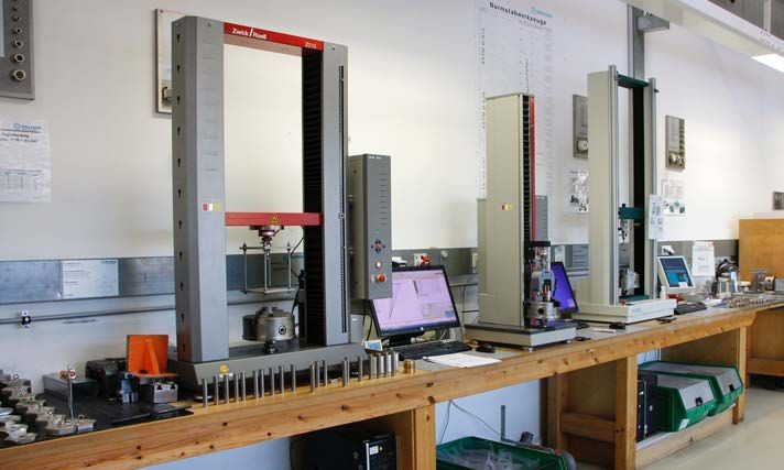
Table of contents

Product designation/Type                             Chapter   Page   Product designation/Type                            Chapter         Page

Dimensions                                                            Standards & certifications

blueglobe – System dimensions                                  480    Information about IP types of protection                              513

blueglobe – Connection dimensions                              481    blueglobe – IP type of protection EN 60529                            514

blueglobe – Mounting distances                                 481    blueglobe – Strain relief classes EN 62444/UL 514 B                   514

UNI Dicht – System dimensions                                  482    UNI Dicht – Strain relief class EN 62444/UL 514 B                     516

UNI Dicht – Connection dimensions                              484    blueglobe – Impact testing as per EN 62444                            517

UNI Dicht – Mounting distances                                 485    PFLITSCH test laboratory                                              518

Instructions                                                          Materials

blueglobe – Assembly instructions                              487    Material characteristics                                              519

blueglobe – Tightening torques                                 488

UNI Dicht – Tightening torques                                 489

Splittable cable gland systems – Assembly instructions         490

blueglobe TRI – Assembly instructions inclusive of             494
tightening torques

UNI IRIS EMV Dicht/UNI HF Dicht – Assembly instructions        495

UNI Entstör Dicht/UNI EMC Dicht – Assembly instructions        496

blueglobe AC – Assembly instructions inclusive of tighten-     497
ing torques

blueglobe EMC – Assembly instructions inclusive of tight-      498
ening torques

blueglobe CLEAN Plus – Assembly instructions inclusive of      499
tightening torques

blueglobe TRI CLEAN Plus – Assembly instructions inclusive     501
of tightening torques

ProTect – Assembly instruciton inclusive of tightening         504
torques

Instructions for drilling out sealing inserts                  506

Standards & certifications

Overview certifications                                        507

Information about CE, EX, RoHS                                 508

Information about EN 62444, UL, CSA                            509

Information about fire protection UL 94                        510

Information about fire protection in rail vehicles EN 45545    511

Infomation about GL, EAC and salt spray test in accordance     512
with DIN EN ISO 60068-2-52

                                                                                                           Technischer Anhang/Technical appendix ∙ 479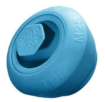
blueglobe-System – Baumaße
 blueglobe system – System dimensions

 Abb. 1                                   Abb. 2                                   Abb. 3                   Abb. 4                                    Abb. 5
 Fig. 1                                   Fig. 2                                   Fig. 3                   Fig. 4                                    Fig. 5

blueglobe-Kabelverschraubungen aus Messing und Edelstahl (Abb. 1)                           blueglobe TRI-Kabelverschraubungen aus Messing und Edelstahl (Abb. 2)
blueglobe cable glands made of brass and stainless steel (fig. 1)                           blueglobe TRI cable glands made of brass and stainless steel (fig. 2)

A               SW x E           D                 C                E             F         A               SW x E           D               C                 E             F
                mm               mm                mm               mm            mm                        mm               mm              mm                mm            mm
M10x1,0         13x14,2            6,0             20,0             6,5           6,5       M12x1,5         17x18,9            5,0             21,0            5,2           8,2
M12x1,5         17x18,9            5,0             21,0             8,2           8,2       M16x1,5         20x22,2            6,0             25,0            9,3           11,2
M16x1,5         20x22,2            6,0             25,0             11,3          11,2      M20x1,5         24x26,5            6,5             29,0            12,3          14,2
M20x1,5         24x26,5            6,5             29,0             14,3          14,2      M25x1,5         30x33              7,5             30,0            17,3          20,2
M25x1,5         30x33              7,5             30,0             20,3          20,2      M32x1,5         36x39,5            8,0             32,0            21,3          25,2
M32x1,5         36x39,5            8,0             32,0             25,3          25,2      M40x1,5         45x48            		15,0            35,0            28,5          32,3
M40x1,5         45x48              8,0             35,0             32,3          32,3      M50x1,5         57x61            		15,0            39,0            37,3          42,3
M50x1,5         57x61            		10,0            39,0             42,3          42,3      M63x1,5         68x72            		20,0            40,0            47,5          54,3
M63x1,5         68x72            		10,0            40,0             54,3          54,3      M75x1,5         81x87            		20,0            47,0            58,4          65,5
M75x1,5         81x87            		15,0            47,0             65,4          65,5      M85x2,0         95x102           		20,0            49,0            67,5          77,5
M85x2,0         95x102           		15,0            49,0             77,5          77,5

blueglobe-Kabelverschraubungen aus PA (Abb. 3)                                              blueglobe CLEAN Plus-Kabelverschraubungen aus Edelstahl (Abb. 4)
blueglobe cable glands made of PA (fig. 3)                                                  blueglobe CLEAN Plus cable glands made of stainless steel (fig. 4)

A               SW x E           D                 C                E             F         A             SW1/SW2 x E2       D            C2           C              E        F
                mm               mm                mm               mm            mm                      mm                 mm           mm           mm             mm       mm
M12x1,5         17x19,5            8,0             23,0             7,6           8,2       M8x1,0        7/11x11,9            4,5        12,0          15,0          5,4      5,2
M16x1,5         20x22,8            9,0             27,0             11,3          11,2      M10x1,0       10/15x16,5           6,0        15,0          19,0          8,2      7,2
M20x1,5         24x27              9,0             33,0             14,4          14,2      M12x1,5       10/17x19,4           7,0        15,0          19,0          8,2      8,2
M25x1,5         30x34              9,0             34,0             20,3          20,2      M16x1,5       14/20x23,4           9,0        18,0          21,0          11,3     11,2
M32x1,5         36x41            		11,0            35,0             25,3          25,2      M20x1,5       19/24x27,4           9,0        21,0          27,0          14,3     14,1
M40x1,5         45x49,5          		12,0            38,0             32,3          32,3      M25x1,5       24/30x33,4         		10,0       23,0          27,0          20,3     20,2
M50x1,5         57x61            		15,0            47,0             42,3          42,1      M32x1,5       30/36x39,4         		11,0       24,0          27,0          25,3     26,0
M63x1,5         70x75            		15,0            49,0             54,3          54,0      M40x1,5       36/45x48,4         		11,0       28,0          32,0          32,3     33,0
                                                                                            M50x1,5       46/55x58,4         		11,0       29,0          34,0          42,3     42,3
                                                                                            M63x1,5       60/68x71,4         		11,0       29,0          33,0          56,0     56,0

blueglobe CLEAN Plus-Kabelverschraubungen aus PA (Abb. 4)                                   blueglobe TRI CLEAN Plus-Kabelverschraubungen aus Edelstahl (Abb. 5)
blueglobe CLEAN Plus cable glands made of PA (fig. 4)                                       blueglobe TRI CLEAN Plus cable glands made of stainless steel (fig. 5)

A             SW1/SW2 x E2       D            C2           C               E        F       A             SW1/SW2 x E2      D             C2           C              E        F
              mm                 mm           mm           mm              mm       mm                    mm                mm            mm           mm             mm       mm
M16x1,5       14/22x24,9          9,0         20,0          25,0           10,0     11,2    M12x1,5       10/17x19,4          7,0         15,0          19,0          5,2      8,2
M20x1,5       18/26x28,9          9,0         25,0          30,0           12,5     14,1    M16x1,5       14/20x23,4          9,0         18,0          21,0          9,3      11,2
M25x1,5       24/32x34,9         		10,0       27,0          30,0           18,5     20,2    M20x1,5       19/24x27,4          9,0         21,0          27,0          12,3     14,1
M32x1,5       30/38x40,9         		11,0       28,0          31,0           25,3     26,0    M25x1,5       24/30x33,4        		11,0        23,0          27,0          17,3     20,2
                                                                                            M32x1,5       30/36x39,4        		12,0        24,0          27,0          21,3     26,0
                                                                                            M40x1,5       36/45x48,4        		22,5        28,0          32,0          28,5     33,0

480 ∙ Technischer Anhang/Technical appendix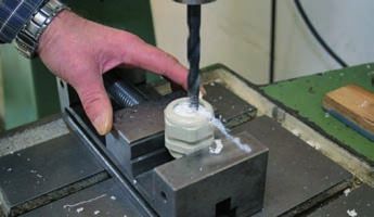
blueglobe – Anschlussmaße
 blueglobe – Connection dimension

                                                                                                               Metrische Gewinde gemäß EN 60423
                                                                                                               Metric thread as per EN 60423

 Abb. 1                                                 Abb. 2 – Bis auf Gewindeaußen-Ø (A) angesenkt
 Fig. 1                                                 Fig. 2 – Up to major diameters of thread countersunk (A)

Metr. Gewinde                                     Kerndurchmesser max.                               Nennmaß                                     Durchgangsbohrung
Metric thread                                     Core diameter max.                                 Nominal size                                Through bore
EN 60423                                          d1                                                 ØA                                          Ø d2
                                                  mm                                                 mm                                          mm (0/+0,2 mm)
M10x1,0                                             8,747                                            10                                          10
M12x1,5                                            10,128                                            12                                          12
M16x1,5                                            14,128                                            16                                          16
M20x1,5                                            18,128                                            20                                          20
M25x1,5                                            23,128                                            25                                          25
M32x1,5                                            30,128                                            32                                          32
M40x1,5                                            38,128                                            40                                          40
M50x1,5                                            48,128                                            50                                          50
M63x1,5                                            61,128                                            63                                          63
M75x1,5                                            73,128                                            75                                          75
M85x2,0                                            82,508                                            85                                          85

                                                                                                      i      M12 PA muss auf 13,0 mm bis 13,5 mm im Außendurchmesser angesenkt werden.
                                                                                                             Countersunk outer thread down to 13.0 mm up to 13.5 mm for M12 made of PA.

 blueglobe – Montageabstände
 blueglobe – Mounting distances

                                                            Montageabstände Kabelverschraubungen
                                                            Metrisches Gewinde EN 60423
                                                            Gewindebohrung, ohne Gegenmutter, Frontmontage
                                                            Werkstoffe:         Ms, VA, PA
                                                            Montagewerkzeug: Steckschlüsselreihe SSG
                                                                                Variabler Montageschlüssel VMS
                                                            Mounting distances cable glands
                                                            Metric thread EN 60423
                                                            Threaded hole, without locknut, front mounting
                                                            Materials:                 Brass, VA, PA
                                                            Mounting tool:             Socket wrench range SSG
                                                                                       Variable mounting wrench VMS

 Abb. 1
 Fig. 1

blueglobe-Kabelverschraubungen aus Messing (CuZn39Pb3), Edelstahl (1.4305 und 1.4571) und PA
blueglobe cable glands made of brass (CuZn39Pb3), stainless steel (AISI 303 and AISI 316Ti) and PA
                      M12               M16              M20                M25               M32                  M40        M50              M63              M63PA           M75

 mm        SWxE       17x18,9           20x22,2          24x26,5            30x33             36x39,5              45x48      57x61            68x72            70x75           81x87

 M12       17x18,9    22,7              24,4             27,3               31,6              35,3                 40,5       50,2             56,6             57,7            64,7
 M16       20x22,2    24,4              26               28,9               33,2              36,9                 42,1       51,8             58,2             59,3            66,3
 M20       24x26,5    27,3              28,9             31,1               35,4              39,1                 44,3       54               60,4             61,5            68,5
 M25       30x33      31,6              33,2             35,4               38,6              42,3                 47,5       57,2             63,6             64,7            71,7
 M32       36x39,5    35,3              36,9             39,1               42,3              45,6                 50,8       60,5             66,9             68              75
 M40       45x48      40,5              42,1             44,3               47,5              50,8                 55         64,7             71,1             72,2            79,2
 M50       57x61      50,2              51,8             54                 57,2              60,5                 64,7       71,2             77,6             78,7            85,7
 M63       68x72      56,6              58,2             60,4               63,6              66,9                 71,1       77,6             83,1             84,2            91,2
 M63PA 70x75          57,7              59,3             61,5               64,7              68                   72,2       78,7             84,2             85,7            92,7
 M75       81x87      64,7              66,3             68,5               71,7              75                   79,2       85,7             91,2             92,7            98,7
SW = Schlüsselweite/E = Eckmaß
SW = spanner width/E = width across corners
                                                                                                                                                      Technischer Anhang/Technical appendix ∙ 481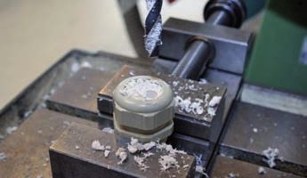
UNI Dicht-System – Baumaße metrisch
UNI Dicht system – System dimensions metric
Abb. 1 Abb. 2 Abb. 3 Abb. 4 Abb. 5
Fig. 1 Fig. 2 Fig. 3 Fig. 4 Fig. 5
UNI Dicht-Kabelverschraubungen aus Messing (CuZn39Pb3), Edelstahl (1.4305) und Zinkdruckguss (ZnAl4CU1)
UNI Dicht cable glands made of brass (CuZn39Pb3), stainless steel (AISI 303) and zinc die-casting (ZnAl4CU1)
A SW1xE1/SW2xE2 D C1 C2 C3 C4 C5 C6 E F
mm mm mm mm mm mm mm mm mm
M4x0,7 6x6,8 2,7 8,8 - - - - - 2,0 2,0
M6x0,75 8x9 4,5 14,0 - - - - - 3,5 3,0
M8x1,0 11x12,2 6,5 15,5 - - - - - 5,0 4,5
M10x1,0 14x15,5 5,0 19,5 - - - - - 6,5 7,0
M10x1,5 14x15,5 5,0 19,5 - - - - - 6,5 7,0
M12x1,5 14x15,5 5,0 19,0 53,0 - - - - 7,0 7,0
M16x1,5 18x20/17x18,9 6,0 20,0 66,0 38,0 42,0 25,0 46,0 9,7 10,0
M20x1,5 22x24,4 6,5 21,0 77,0 40,0 48,0 32,0 47,0 13,5 13,5
M20x1,5* 24x26,7 6,5 21,0 - 40,0 - - 47,0 16,0 16,0
M25x1,5** 28x31,2/24x26,7 7,5 21,0 83,0 40,0 49,0 35,0 47,0 16,0 16,0
M25x1,5*** 27x29,5/24x26,7 7,5 21,0 - - - - - 16,0 16,2
M32x1,5** 35x38,5/30x33,5 8,0 26,0 80,0 44,0 - - - 21,0 18,5/21,0
M32x1,5*** 36x39,5/30x33,5 8,0 26,0 - - - - - 21,3 18,5/21,0
M40x1,5** 43x47,3/40x43,5 8,0 29,0 84,0 47,0 - - 55,0 28,5 29,0
M40x1,5*** 46x50/41x44,5 8,0 28,0 - - - - - 28,5 29,0
M50x1,5 54x58/50x54 10,0 30,0 - 51,0 - - 61,0 37,5 38,0
M50x1,5* 57x61 10,0 32,0 - - - - - 42,0 42,0
M50x1,5*** 55x60,5/50x54 10,0 29,0 - - - - - 37,5 38,0
M63x1,5** 68x74/64x69 10,0 30,0 - - - - - 47,0 47,0
M63x1,5*** 68x74/65x70 10,0 30,0 - - - - - 47,0 47,0
M75x1,5 81x87 15,0 46,0 - - - - - 64,0 59,5
M80x2,0 95x102 15,0 61,0 - - - - - 72,5 72,5
M90x2,0 120x128 20,0 62,0 - - - - - 80,0 87,0
M100x2,0 120x128 20,0 63,0 - - - - - 92,0 87,0/92,0
M120x2,0 145x155 30,0 70,0 - - - - - 110,0 110,0
* Erweitert ** Messing *** Edelstahl
UNI Dicht-Kabelverschraubungen aus PVDF und Polycarbonat * Extended ** Brass *** Stainless steel
UNI Dicht cable glands made of PVDF and polycarbonate
A SW1xE1/SW2xE2 D C1 C2 C3 C4 C5 C6 E F
mm mm mm mm mm mm mm mm mm
M12x1,5 15x16,5 8,0 23,0 55,0 - - - - 7,0 6,8
M16x1,5 19x21,2 9,0 22,0 68,0 41,0 38,0 23,0 47,0 10,0 10,0
M20x1,5 24x26,5/22x24,4 9,0 23,0 75,0 42,0 46,0 28,0 - 12,0 11,0
M20x1,5 24x26,5 9,0 23,0 80,0 42,0 - - 49,0 14,0 13,5
M25x1,5* 30x33,5/27x29,5 9,0 24,0 85,0 42,0 52,0 32,0 - 16,0 16,0
M25x1,5** 29x31,5/27x29,5 9,0 26,0 85,0 - - - 49,0 16,0 16,0
M32x1,5* 36x39,5/33x36,5 11,0 29,0 82,0 46,0 - - - 21,0 21,0
M32x1,5** 38x42/33x36,5 11,0 29,0 82,0 - - - - 21,0 21,0
M40x1,5* 46x50/43x46,5 11,5 33,0 84,0 - - - - 28,5 28,0
M40x1,5** 46x50/43x46 11,5 34,0 88,0 - - - 63,0 28,5 28,0
M50x1,5 56x61/53x57 14,0 34,0 - - - - 63,0 37,0 37,0
* PC ** PVDF
482 ∙ Technischer Anhang/Technical appendix * PC ** PVDF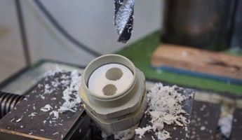
UNI Dicht-System – Baumaße Pg
 UNI Dicht system – System dimensions Pg

                                                                                                                                                    C4

                                                                                                                                   C5
                                                                                                                                                                SW2 xE 2

                                                                                                                                    SW1 xE 1    A

        Abb. 1                                          Abb. 2                                            Abb. 3                    Abb. 4
        Fig. 1                                          Fig. 2                                            Fig. 3                    Fig. 4

UNI Dicht-Kabelverschraubungen aus Messing (CuZn39Pb3), Edelstahl (1.4305) und Zinkdruckguss (ZnAl4CU1)
UNI Dicht cable glands made of brass (CuZn39Pb3), stainless steel (AISI 303) and zinc die-casting (ZnAl4CU1)

A                SW1xE1/SW2xE2          D                   C1                  C2                  C3             C4     C5            E                 F
                                        mm                  mm                  mm                  mm             mm     mm            mm                mm

Pg 7             14x15,5                  5,0                20,0                53,0                 -             -      -            7,0               7,0
Pg 9             18x20/17x18,9            8,5                20,0                64,0                40,0          41,0   24,5          9,7               10,0
Pg 11*           22x24,4/20x22,2          8,0                20,0                66,0                 -            43,4   27,0          11,5              11,5
Pg 11**          22x24,4                  6,0                20,0                 -                  40,0           -      -            11,5              11,5
Pg 13,5          24x26,7/22x24,4          8,0                21,0                77,0                40,0          46,6   31,0          13,5              13,5
Pg 16            26x29/24x26,7            8,0                21,0                83,0                40,0          48,7   33,0          16,0              16,2
Pg 21            35x38,5/30x33,5        		11,0               25,0                80,0                44,0          59,5   39,5          21,3              18,5
Pg 29*           43x47,5/40x43,5        		11,0               28,0                84,0                47,0           -      -            28,5              29,0
Pg 29**          41x44,5                  8,0                28,0                 -                   -             -      -            28,5              29,0
Pg 36            50x54                    9,0                28,0                 -                  50,0           -      -            37,5              38,0
Pg 42*           57x61                  		10,0               30,0                 -                   -             -      -            42,0              42,0
Pg 42**          60x65                  		10,0               30,0                 -                   -             -      -            42,0              42,0
Pg 48*           64x69                  		10,0               30,0                 -                   -             -      -            47,0              47,0
Pg 48**          65x70                  		10,0               30,0                 -                   -             -      -            47,0              47,0
G2 1/2"          81x87                  		15,0               40,0                 -                   -             -      -            64,0              59,5
G3"              95x102                 		15,0               40,0                 -                   -             -      -            72,0              72,5

* Messing ** Edelstahl
* Brass ** Stainless steel

UNI Dicht-Kabelverschraubungen aus PVDF und Polycarbonat
UNI Dicht cable glands made of PVDF and polycarbonate

A                   SW1xE1/SW2xE2       D                   C1                  C2                 C3              C4     C5            E                 F
                                        mm                  mm                  mm                 mm              mm     mm            mm                mm

Pg 7                15x16,5               8,0                23,0                58,0                 -             -      -            7,0               6,8
Pg 9                19x21,2               8,0                23,0                65,0                41,0          40,0   23,0          10,0              10,0
Pg 11               22x24,4               9,0                24,0                67,0                42,0          43,0   25,0          11,5              11,0
Pg 13,5             24x26,4               9,0                24,0                80,0                42,0          47,0   28,0          14,0              13,0
Pg 16               27x29,5             		10,0               24,0                81,0                42,0          52,0   32,0          16,0              16,0
Pg 21               33x36,5             		11,0               29,0                82,0                46,0           -      -            21,0              21,0
Pg 29               43x46,5             		11,0               33,0                88,0                 -             -      -            31,5              28,0
Pg 36               53x57               		14,0               33,0                 -                   -             -      -            37,0              37,0
Pg 42*              60x65               		13,0               38,0                 -                   -             -      -            42,0              43,0
Pg 48*              65x70               		14,0               41,0                 -                   -             -      -            47,0              47,0

* POM
* POM

                                                                                                                                 Technischer Anhang/Technical appendix ∙ 483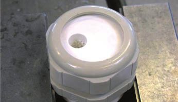
UNI Dicht – Anschlussmaße metrisch
UNI Dicht – Connection dimensions metric
Metrische Gewinde gemäß EN 60423
Metric thread as per EN 60423
d1
A
d2
Abb. 1 Abb. 2 – Bis auf Gewindeaußen-Ø (A) angesenkt
Fig. 1 Fig. 2 – Up to major diameters of thread countersunk (A)
Metr. Gewinde Kerndurchmesser max. Nennmaß Steigung Durchgangsbohrung
Metric thread Core diameter max. Nominal size Pitch Through bore
EN 60423 d1 ØA P Ø d2
mm mm mm (0/+0,2 mm)
M4x0,7 3,141 4 0,7 4
M6x0,75 5,058 6 0,75 6
M8x1,0 6,747 8 1 8
M10x1,0 8,747 10 1 10
M10x1,5 8,128 10 1,5 10
M12x1,5 10,128 12 1,5 12
M16x1,5 14,128 16 1,5 16
M20x1,5 18,128 20 1,5 20
M25x1,5 23,128 25 1,5 25
M32x1,5 30,128 32 1,5 32
M40x1,5 38,128 40 1,5 40
M50x1,5 48,128 50 1,5 50
M63x1,5 61,128 63 1,5 63
M75x1,5 73,128 75 1,5 75
M80x2,0 77,508 80 2 80
M90x2,0 87,508 90 2 90
M100x2,0 97,508 100 2 100
M120x2,0 117,508 120 2 120
UNI Dicht – Anschlussmaße Pg
UNI Dicht – Connection dimensions Pg
Pg-Gewinde
Pg thread
d1
A
d2
Abb. 1 Abb. 2 – Bis auf Gewindeaußen-Ø (A) angesenkt
Fig. 1 Fig. 2 – Up to major diameters of thread countersunk (A)
Pg-Gewinde Kerndurchmesser max. Nennmaß Steigung Durchgangsbohrung
Pg thread Core diameter max. Nominal size Pitch Bore through
DIN 40430 d1 ØA P Ø d2
mm mm mm (0/+0,2 mm)
Pg 7 11,280 12,5 1,27 12,5
Pg 9 13,860 15,2 1,41 15,2
Pg 11* 17,260 18,6 1,41 18,5
Pg 13,5 19,060 20,4 1,41 20,5
Pg 16 21,160 22,5 1,41 22,5
Pg 21 26,780 28,3 1,59 28,5
Pg 29* 35,480 37 1,59 37
Pg 36 45,480 47 1,59 47
Pg 42* 52,480 54 1,59 54
Pg 48* 57,780 59,3 1,59 59,5
* Messing
484 ∙ Technischer Anhang/Technical appendix
* Brass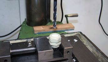
UNI Dicht – Montageabstände metrisch
 UNI Dicht – Mounting distances metric

                                                            Montageabstände Kabelverschraubungen
                                                            Metrisches Gewinde EN 60423
                                                            Gewindebohrung, ohne Gegenmutter, Frontmontage
                                                            Werkstoffe:         Ms, VA, PVDF, PC
                                                            Montagewerkzeug: Steckschlüsselreihe SSG
                                                                                Variabler Montageschlüssel VMS
                                                            Mounting distances cable glands
                                                            Metric thread EN 60423
                                                            Threaded hole, without counter nut, front mounting
                                                            Materials:               Brass, VA, PVDF, PC
                                                            Mounting tool:           Socket wrench range SSG
                                                                                     Variable mounting wrench VMS

 Abb. 1
 Fig. 1

UNI Dicht-Kabelverschraubungen aus Messing (CuZn39Pb3), Edelstahl (1.4305), PC und PVDF
UNI Dicht cable glands made of brass (CuZn39Pb3) and stainless steel (AISI 303), PC and PVDF

 SWxE        14x    15x     18x     19x       22x    24x     27x    28x     29x     30x        35x    36x    38x   41x     43x     46x    53x     54x     55x    57x     60x     68x    81x
             15,5   17      20      21        24,4   26,5    29,5   31,2    31,5    33,5       38,5   39,5   42    44,5    47,3    50     57      58      60,5   61      65      74     87
 14x15,5     18     19      21      21        23     25      26     27      27      28         32     32     33    36      36      38     43      44      44     47      48      53     61
 15x17       19     19      21      22        24     26      28     28      29      30         33     33     33    36      37      39     44      45      45     48      50      54     62
 18x20       21     21      23      23        25     27      28     29      30      31         34     34     34    38      38      40     45      46      46     49      50      55     63
 19x21       21     22      23      24        26     27      29     30      30      31         34     35     36    38      39      41     46      47      47     49      50      56     64
 22x24,4     23     24      25      26        27     29      31     31      32      33         36     37     38    40      40      42     48      49      49     51      52      57     65
 24x26,5     25     26      27      27        29     30      32     32      33      34         37     38     39    41      42      43     49      50      50     52      53      58     66
 27x29,5     26     28      28      29        31     32      34     34      35      36         39     39     41    43      43      45     50      52      52     53      55      60     68
 28x31,2     27     28      29      30        31     32      34     35      35      36         39     40     41    43      44      46     51      52      52     54      56      61     69
 29x31,5     27     29      30      30        32     33      35     35      35      36         40     40     41    44      44      46     51      52      52     55      56      61     69
 30x33,5     28     30      31      31        33     34      36     36      36      37         41     41     42    45      45      47     52      53      53     56      57      62     70
 35x38,5     32     33      34      34        36     37      39     39      40      41         43     44     45    47      48      49     55      56      56     58      59      64     72
 36x39,5     32     33      34      35        37     38      39     40      40      41         44     44     45    48      48      50     55      56      56     59      60      65     73
 38x42       33     33      34      36        38     39      41     41      41      42         45     45     47    49      59      51     56      58      58     60      61      66     74
 41x44,5     36     36      38      38        40     41      43     43      44      45         47     48     49    50      51      53     58      59      59     61      63      68     76
 43x47,3     36     37      38      39        40     42      43     44      44      45         48     48     49    51      52      54     59      60      60     62      64      69     77
 46x50       38     39      40      41        42     43      45     46      46      47         49     50     51    53      54      55     60      61      61     64      65      70     78
 53x57       43     44      45      46        48     49      50     51      51      52         55     55     56    58      59      60     64      65      65     67      69      74     82
 54x58       44     45      46      47        49     50      52     52      52      53         56     56     58    59      60      61     65      65      65     68      69      74     82
 55x60,5     44     45      46      47        49     50      52     52      52      53         56     56     58    59      60      61     65      65      67     69      70      75     83
 57x61       47     48      49      49        51     52      53     54      55      56         58     59     60    61      62      64     67      68      69     69      70      76     84
 60x65       48     50      50      50        52     53      55     56      56      57         59     60     61    63      64      65     69      69      70     70      72      78     86
 68x74       53     54      55      56        57     58      60     61      61      62         64     65     66    68      69      70     74      74      75     76      78      82     90
 81x87       61     62      63      64        65     66      68     69      69      70         72     73     74    76      77      78     82      82      83     84      86      90     97
SW = Schlüsselweite/E = Eckmaß
SW = spanner width/E = width across corners                                                                  i     Montageabstände für UNI Dicht Erweitert bitte aus den Montageabstän-
                                                                                                                   den Pg entnehmen
                                                                                                                   For mounting distances for UNI Dicht Extended, please see mounting distances
                                                                                                                   Pg.

                                                                                                                                                   Technischer Anhang/Technical appendix ∙ 485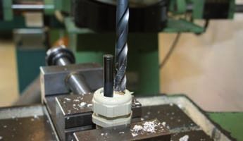
UNI Dicht – Montageabstände Pg
 UNI Dicht – Mounting distances Pg

                                                            Montageabstände Kabelverschraubungen
                                                            Pg-Gewinde
                                                            Gewindebohrung, ohne Gegenmutter, Frontmontage
                                                            Werkstoffe:        Ms, VA, PVDF, PC
                                                            Montagewerkzeug: Steckschlüsselreihe SSG
                                                                               Variable Montageschlüssel VMS
                                                            Mounting distances cable glands
                                                            Pg thread
                                                            Threaded hole, without counter nut, front mounting
                                                            Materials:                 Brass, VA, PVDF, PC
                                                            Mounting tool:             Socket wrench range SSG
                                                                                       Variable mounting wrench VMS

 Abb. 1
 Fig. 1

UNI Dicht-Kabelverschraubungen aus Messing (CuZn39Pb3), Edelstahl (1.4305), PC und PVDF
UNI Dicht cable glands made of brass (CuZn39Pb3) and stainless steel (AISI 303), PC and PVDF
 SWxE       14x       17x        19x       20x       22x       24x       27x       30x         33x    40x    41x   43x    50x   53x   57x   60x   64x   65x
            15,5      18,9       21        22,2      24,4      26,7      29,5      33,5        36,5   43,5   44    46,3   54    57    61    65    69    70

 14x15,5    18        20         21        22        23        25        26        28          30     34     35    36     40    42    44    48    49    51
 17x18,9    20        21         23        24        25        26        28        30          31     35     37    38     42    44    46    50    51    53
 19x21,0    21        23         24        25        26        28        29        31          33     37     38    39     43    45    47    51    52    54
 20x22,2    22        24         25        26        26        28        30        32          33     37     39    40     44    46    48    52    53    55
 22x24,4    23        25         26        26        27        29        31        33          34     36     40    41     45    47    50    53    55    56
 24x26,7    25        26         28        28        29        30        32        34          35     39     41    42     46    48    50    54    55    57
 27x29,5    26        28         29        30        31        32        33        35          37     41     42    43     47    49    51    55    56    58
 30x33,5    28        30         31        32        33        34        35        37          39     43     44    45     49    51    53    57    58    60
 33x36,5    30        31         33        33        34        35        37        39          41     44     46    47     51    53    55    59    60    62
 40x43,5    34        35         37        37        36        39        41        43          44     48     50    51     55    57    59    62    64    65
 41x44,5    35        37         38        39        40        41        42        44          46     50     51    52     55    57    59    63    64    66
 43x46,3    36        38         39        40        41        42        43        45          47     51     52    52     56    58    60    64    65    67
 50x54,0    40        42         43        44        45        46        47        49          51     55     55    56     60    62    64    67    69    71
 53x57,0    42        44         45        46        47        48        49        51          53     57     57    58     62    64    66    69    71    72
 57x61,0    44        46         47        48        50        50        51        53          55     59     59    60     64    66    68    71    73    74
 60x65,0    48        50         51        52        53        54        55        57          59     62     63    64     67    69    71    73    75    76
 64x69,0    49        51         52        53        55        55        56        58          60     64     64    65     69    71    73    75    78    78
 65x70,0    51        53         54        55        56        57        58        60          62     65     66    67     71    72    74    76    78    79
SW = Schlüsselweite/E = Eckmaß
SW = spanner width/E = width across corners

486 ∙ Technischer Anhang/Technical appendix
blueglobe – Montageanleitung
blueglobe – Assembly instructions
A
B
A = Dichtbereich ohne Inlet
B = Dichtbereich mit Inlet
(globemarker ab Größe M20)
A = sealing range with inlet
B = sealing range without inlet
(globemarker from size M20)
1 2
Bei großem Kabeldurchmesser Inlet entfernen. Dazu den Schrau- Zur optimalen Montage von Verschraubungen empfehlen wir die
bendreher senkrecht einstechen und Inlet aushebeln. Verwendung der PFLITSCH-Steckschlüssel SSG.
In case of a large cable diameter remove inlet. To do so, push the screw- For the optimal installation of glands we recommend using the PFLITSCH
driver in vertically and remove inlet. socket wrench SSG.
SICHERHEITSHINWEISE!
SAFETY INSTRUCTIONS!
Bei Dichteinsätzen mit Inlet muss das Kabel entweder mit außen-
liegendem oder ohne globemarker installiert werden, um IP 68 zu
gewährleisten.
Bei den zweiteiligen HT-Dichteinsätzen M32 bis M63 ist vor dem
Anziehen der Druckschraube das Inlet exakt zu positionieren.
If the cable is installed with an inlet in the sealing insert, the globemarker
has to be outside or removed to guarantee IP 68.
With the two-part HT sealing inserts M32 to M63, the inlet must be posi-
tioned exactly before tightening the pressure screw.
Technischer Anhang/Technical appendix ∙ 487blueglobe – Maximale Anzugsdrehmomente
blueglobe – Maximum tightening torque
Die Druckschraube ist so weit anzuziehen, bis der Dichteinsatz
bündig zur Oberkante der Druckschraube ist. Dabei dürfen die
maximalen Anzugsdrehmomente nicht überschritten werden.
Ein Unterschreiten ist jedoch möglich. Dies gilt für Wandungen
mit Gewinde und bei Durchgangsbohrungen mit Gegenmutter.
Tighten the pressure screw until the sealing insert is flush with the
outer edge of the pressure screw. Do not exceed the maximum per-
missible tightening torque. Note: It is possible to exceed it. This applies
to walls with threads and through-holes with a locknut.
Abb. 1 – Druckschraube anziehen, bis Dichteinsatz und Druckschraube auf einer Höhe sind
Fig. 1 – Tighten the pressure screw until pressure screw and sealing insert are at the same level.
blueglobe Ms/VA blueglobe PA
blueglobe brass/VA blueglobe PA
Metr. Gewinde Anzugsdrehmoment Metr. Gewinde Anzugsdrehmoment
Metric thread Nominal torque Metric thread Nominal torque
M10x1,0 3,0 Nm M12x1,5 1,5 Nm
M12x1,5 5,0 Nm M16x1,5 4,5 Nm
M16x1,5 8,0 Nm M20x1,5 8,0 Nm
M20x1,5 10,0 Nm M25x1,5 10,0 Nm
M25x1,5 15,0 Nm M32x1,5 12,0 Nm
M32x1,5 15,0 Nm M40x1,5 14,0 Nm
M40x1,5 20,0 Nm M50x1,5 25,0 Nm
M50x1,5 30,0 Nm M63x1,5 30,0 Nm
M63x1,5 35,0 Nm
M75x1,5
M85x2,0
80,0 Nm
100,0 Nm
i Der Doppelnippel ist mit dem aufgeführten maximalen Anzugsdrehmoment
anzuziehen.
The douple nipple must be tightened to the maximum tightening torque listed.
488 ∙ Technischer Anhang/Technical appendixUNI Dicht – Maximale Anzugsdrehmomente
UNI Dicht – Maximum tightening torques
UNI Dicht metrisch Metall UNI Dicht metrisch Kunststoff
UNI Dicht metric metal UNI Dicht metric plastic
Metr. Gewinde Anzugsdrehmoment Metr. Gewinde Anzugsdrehmoment
Metric thread Nominal torque Metric thread Nominal torque
M4x0,7 0,7 Nm M12x1,5 1,5 Nm
M6x0,75 2,0 Nm M16x1,5 3,0 Nm
M8x1,0 4,0 Nm M20x1,5 4,0 Nm
M10x1,0 6,0 Nm M25x1,5 6,0 Nm
M12x1,5 6,0 Nm M32x1,5 8,0 Nm
M16x1,5 8,0 Nm M40x1,5 10,0 Nm
M20x1,5 10,0 Nm M50x1,5 15,0 Nm
M25x1,5 10,0 Nm M63x1,5 15,0 Nm
M32x1,5 15,0 Nm
M40x1,5 20,0 Nm
M50x1,5 30,0 Nm
M63x1,5 40,0 Nm
M75x1,5 80,0 Nm
M80x2,0 80,0 Nm
M90x2,0 140,0 Nm
M100x2,0 140,0 Nm
M120x2,0 200,0 Nm
UNI Dicht Pg Metall UNI Dicht Pg Kunststoff
UNI Dicht Pg metal UNI Dicht Pg plastic
Pg-Gewinde Anzugsdrehmoment Pg-Gewinde Anzugsdrehmoment
Pg thread Nominal torque Pg thread Nominal torque
Pg 7 6,0 Nm Pg 7 2,5 Nm
Pg 9 8,0 Nm Pg 9 4,0 Nm
Pg 11 10,0 Nm Pg 11 4,0 Nm
Pg 13,5 10,0 Nm Pg 13,5 4,0 Nm
Pg 16 10,0 Nm Pg 16 6,0 Nm
Pg 21 15,0 Nm Pg 21 8,0 Nm
Pg 29 20,0 Nm Pg 29 10,0 Nm
Pg 36 30,0 Nm Pg 36 15,0 Nm
Pg 42* 30,0 Nm Pg 42 15,0 Nm
Pg 48 40,0 Nm Pg 48 15,0 Nm
* Messing
* Brass i Tabellenwerte sind allgemeine Vorgaben. Das Drehmoment hängt vom
verwendeten Kabel und von der Einsatzdichtung ab, sollte aber die in der
Tabelle angegebenen Werte nicht überschreiten.
Table figures are general terms of reference. The torque depends on the cable used
and the insert sealing; it should not, however, exceed the figures stated in the table.
Technischer Anhang/Technical appendix ∙ 489UNI Split Gland – Montageanleitung
UNI Split Gland – Assembly instructions
1 M20, M32
2
1x
2x
1x
1x
1x
1x Art.-Nr.
Art. no.
M25 WSZ 16
Bestandteile: teilbarer Doppelnippel, Dichteinsatz, teilbare Als Montagehilfe der Dichteinsätze empfehlen wir unsere Spreiz-
Druckschraube zange.
Components: Splittable double nipple, sealing insert, splittable pressure We recommend you use our spreader pliers to help you insert the sealing
screw inserts.
3 4
click!
Dichteinsatz am Kabel montieren Doppelnippel zusammensetzen
Fit sealing insert to cable Assemble double nipple
5 6
Art.-Nr.
Art.-No.
SSG 30gV
SSG 35gV
SSG 46gV
M20 M25 M25 HD M32
30 35 36 46
4 6 12 10
Zum Festschrauben empfehlen wir die Verwendung eines Gleit- Doppelnippel anziehen
mittels auf der Schaumdichtung (z. B. FÖRCH Vaselinestift). Tighten double nipple
We recommend you apply an anti-seize agent to the foam seal when tight-
ening, e.g. FÖRCH Vaseline Stick.
490 ∙ Technischer Anhang/Technical appendixUNI Split Gland – Montageanleitung
UNI Split Gland – Assembly instructions
7 8
Dichteinsatz in Doppelnippel eindrücken Druckschraube zusammensetzen
Press sealing insert into double nipple Assemble pressure screw
8a (M25) 9
M25
2.
1. M20
30
M25 M25 HD M32
35 36 46
2 4 13 10
Druckschraube zusammensetzen Druckschraube anziehen
Assemble pressure screw Tighten pressure screw
UNI Split Gland – Demontage
UNI Split Gland – Disassembly
1 Demontage
Disassembly
2 Demontage
Disassembly
2.
1.
Zur Demontage die Druckschraube lösen Dichteinsatz herausziehen und Doppelnippel lösen
Unscrew pressure screw to disassemble gland Pull out sealing insert and release double nipple
3 Demontage
Disassembly
2.
1.
3.
Kabelverschraubung in Einzelteile zerlegen
Completely take apart cable gland
Technischer Anhang/Technical appendix ∙ 491UNI Flansch – Montageanleitung
UNI flange – Assembly instructions
1
DIN EN ISO 4762
1x 3x 4x M4
1x
3x
3x
Bestandteile: teilbarer UNI Flansch, 3x Dichteinsatz, 3x teilbare Druckschraube. Zur Befestigung werden gängige M4 Schrauben benötigt.
Components: Splittable UNI flange, 3 sealing inserts, 3 splittable pressure screws Standard M4 screws are required for fastening.
2
0,2
130
0,2
0,2
112
32
360,2
,5
Art.-Nr.
Ø4
Art. no.
WSZ 16
Als Montagehilfe der Dichteinsätze empfehlen wir unsere Spreizzange.
We recommend you use our spreader pliers to help you insert the sealing inserts.
3
Rahmenhälften zusammenstecken
Connect frame halves to one another
492 ∙ Technischer Anhang/Technical appendixUNI Flansch – Montageanleitung
UNI flange – Assembly instructions
4 b 7,5
L
a
L=7,5+a+b
4x M4
MA= 3 Nm
Rahmenhälften mit Befestigungsschrauben montieren (Anzugsdrehmoment 2–3 Nm)
Install frame halves using fastening screws (tightening torque: 2–3 Nm)
5 6
2.
click! 1.
Dichteinsätze in Flanschöffnungen hineindrücken Druckschrauben zusammensetzen und montieren
Press sealing inserts into flange openings Assemble pressure screws and install them
7
4 6
50
5
b
Nm
in.l
SW 35
MA = 4 Nm
Art.-Nr.
Art. no.
SSG 36gV
Druckschrauben anziehen
Tighten pressure screws
Technischer Anhang/Technical appendix ∙ 493blueglobe TRI – Montageanleitung
blueglobe TRI – Assembly instructions
1 C
D
2 Variante 1
Variant 1
B
A
Variante 2
Variant 2
min. a + 5 mm (siehe Tabelle unten)
min. a + 5 mm (see table below)
Bestandteile: Doppelnippel (A), Feder (B), Globe-Dichteinsatz (C), Vorbereitung: Leitung abmanteln, Geflecht mit Isolierband
Druckschraube (D) schützen
Components: Double nipple (A), spring (B), globe-sealing insert (C), Preparation: Dismantle wire, protect braid below
pressure screw (D)
3 4
Kabel mit leichter Drehung einführen Markieren, wenn der Kabelmantel die Feder berührt
Insert cable with slight turning Mark when cable sheath touches spring
5 6
Kabel gemäß Maß a zurückziehen (siehe Tabelle unten) Druckschraube mit Anzugsdrehmoment festziehen (siehe Tabelle
Withdraw cable according to size a (see table below) unten)
Fix pressure screw with nominal torque (see table below)
Tabelle
Table
Art.-Nr. a Maximales Anzugsdrehmoment
Art. no. mm Maximum tightening torque
bg 212ms tri 7 5,0 Nm
bg 216ms tri 8 8,0 Nm
bg 220ms tri 9 10,0 Nm
bg 225ms tri 10 15,0 Nm
bg 232ms tri 11 15,0 Nm
bg 240ms tri 13 20,0 Nm
bg 250ms tri 15 30,0 Nm
bg 263ms tri 15 35,0 Nm
bg 275ms tri 15 80,0 Nm
bg 285ms tri 15 100,0 Nm
494 ∙ Technischer Anhang/Technical appendixUNI IRIS EMV Dicht und UNI HF Dicht – Montageanleitung
UNI IRIS EMC Dicht and UNI HF Dicht – Assembly instructions
Anschlussgewinde-Dichtring U71. UNI IRIS EMV Dicht-Kabelverschraubung, Messing
Connection thread-sealing ring Druckschraube vernickelt
Dichteinsatz
Konen Sealing insert Pressure screw In Abhängigkeit vom Außen-Ø des Kabels und vom
Cones Außen-Ø des Kabelschirmes kommen zwei Montage-
varianten zur Anwendung.
Variante A – abgesetzter Kabelmantel (siehe Abb. 2)
Variante B – durchgängiger Kabelmantel (siehe Abb. 3)
U71. UNI IRIS EMC Dicht cable gland, brass, nickel-plated
Two different installation variants are applied depending on
Kabel the cables and cable shield’s outer diameter.
UNI IRIS-Feder
UNI IRIS spring Cable Variant A – removed outer sheath (see fig. 2)
Gegenmutter Doppelnippel Variant B – continuous outer sheath (see fig. 3)
Locknut Double nipple S
Abb. 1 Montagerichtung
Fig. 1 Installation direction
i Die UNI IRIS EMV Dicht mit den zwei Konen wird auf dem mit Maß S
freigelegten Schirm nach Abb. 1 und Tabelle 1 montiert.
The UNI IRIS EMC Dicht equipped with two cones is installed on the uncovered
shield as per dimension S (see fig. 1 and table 1).
Tabelle 1: Maß S min.
Table 1: Dimension S min.
M 16/18 20 24/25 30/32 40 45/50 56 63/72
Pg 11 13,5 16 21 29 36 42 48
S (mm) 8 8 9 9 11 14 14 16
Abb. 2 – Variante A: abgesetzter Außenmantel Abb. 3 – Variante B: durchgängiger Außenmantel
Fig. 2 – Variant A: removed outer sheath Fig. 3 – Variant B: continuous outer sheath
Anschlussgewinde-Dichtring U87. UNI HF Dicht-Kabelverschraubung, Messing ver-
Connection thread-sealing ring Dichteinsatz nickelt
Kabel
Konen Sealing insert Cable In Abhängigkeit vom Außen-Ø des Kabels und des
Cones Außen-Ø des Kabelschirmes kommen zwei Montage-
varianten zur Anwendung.
Variante A – abgesetzter Kabelmantel (siehe Abb. 2)
Variante B – durchgängiger Kabelmantel (siehe Abb. 3)
U87. UNI HF Dicht cable gland, brass, nickel-plated
Two different installation variants are applied depending on
the cables and cable shield’s outer diameter.
Variant A – removed outer sheath (see fig. 2)
UNI IRIS-Feder Druckschraube
Schirmgeflecht Variant B – continuous outer sheath (see fig. 3)
UNI IRIS spring Pressure screw
Shielding braid
Abb. 1 Montagerichtung
Fig. 1 Installation direction
i Die UNI HF Dicht mit den zwei Konen wird auf dem mit Maß S freigeleg-
ten Schirm nach Abb. 1 und Tabelle 2 montiert.
The UNI HF equipped with two cones is installed on the uncovered shield as per
dimension S (see fig. 1 and table 2).
Tabelle 2: Maß S min.
Table 2: Dimension S min.
M 12 16 20 20 25 32 40 50 50 63 75 80
Pg 7 9 11 13,5 16 21 29 36 42 48 G2 1/2" G3
S (mm) 7 8 8 8 9 9 11 14 14 16 18 20
Abb. 2 – Variante A: abgesetzter Außenmantel Abb. 3 – Variante B: durchgängiger Außenmantel
Fig. 2 – Variant A: removed outer sheath Fig. 3 – Variant B: continuous outer sheath
Technischer Anhang/Technical appendix ∙ 495UNI Entstör Dicht und UNI EMV Dicht – Montageanleitung
UNI Interference Suppression and UNI EMC Dicht – Assembly instructions
U4. UNI Entstör Dicht-Kabelverschraubung
Doppelnippel Messing vernickelt
Dichteinsatz Druckschraube
Double nipple
Sealing insert Pressure screw
U4. UNI Interference Suppression Dicht cable gland (suppres-
sion shielding)
brass, nickel-plated
Schirmgeflecht
Konus
Shielding braid
Cone Kabel
Anschlussgewinde-Dichtring Cable
Connection thread-sealing ring
Abb. 1 Montagerichtung
Fig. 1 Installation direction
i Der Schirm des Kabels/der Leitung wird nach Abb. 1 und Tabelle 1 um
das Maß S freigelegt und leicht aufgeweitet.
The screened braid of the cable has to be shortened and widened slightly as per
dimension S (see fig. 1 and table 1).
Tabelle 1: Maß S min.
Table 1: Dimension S min.
M 10/12 16 - 20 25 32 40 50
Pg 7 9 11 13,5 16 21 29 36
S (mm) 3 5 5 5 6 8 8 8
U40. UNI EMV Dicht-Kabelverschraubung
Doppelnippel Druckschraube
Dichteinsatz Messing vernickelt
Double nipple Pressure screw
Sealing insert U40. UNI EMC Dicht cable gland
Schirmgeflecht
Shielding braid brass, nickel-plated
Konenpaar Kabel
Pair of cones Cable
Anschlussgewinde-Dichtring
Connection thread-sealing ring
Montagerichtung
Abb. 1
Fig. 1
Installation direction i Das Schirmgeflecht des Kabels/der Leitung wird nach Abb. 1 + 2 um das
Maß S von 9 mm bis 12 mm freigelegt und leicht aufgeweitet.
The screened braid of the cable has to be shortened up to a length of 9 mm to
12 mm and to be widened slightly (see fig. 1 + 2).
9 - 12 mm
Abb. 2
Fig. 2
496 ∙ Technischer Anhang/Technical appendixblueglobe AC – Montageanleitung
blueglobe AC – Assembly instructions
1 2
Bestandteile: Adapter mit O-Ring1, Klemmring2, Druckring3, Dich- Adapter1, Doppelnippel5.1, Druckschraube5.2
tung4, Doppelnippel5, Dichteinsatz6 und Druckschraube7 Adapter 1, double nipple 5.1, pressure screw 5.2
Components: Adapter with o-ring 1, clamping ring 2, pressure ring 3, sealing 4,
double nipple 5, sealing insert 6 and pressure screw 7
3 4
Kabel abmanteln, Länge X markieren Kabel mit Länge X einführen
Strip off the cable, mark length X Insert cable with length X
5 6
DN anziehen zum Kontaktieren DS anziehen zur Abdichtung
Tighten double nipple to connect Tighten pressure screw to seal
Tabelle
Table
Art.-Nr. LA X Maximales Anzugsdrehmoment DN Maximales Anzugsdrehmoment DS
Art. no. mm mm Maximum tightening torque DN Maximum tightening torque DS
220bg220msAC11 20 35 15,0 Nm 10,0 Nm
225bg225msAC17 22 37 15,0 Nm 15,0 Nm
232bg232msAC23 26 40 25,0 Nm 15,0 Nm
240bg240msAC31 28 43 20,0 Nm 20,0 Nm
250bg250msAC36 32 49 50,0 Nm 30,0 Nm
263bg263msAC46 32 50 50,0 Nm 35,0 Nm
275bg275msAC61 36 62 80,0 Nm 80,0 Nm
285bg285msAC70 38 64 100,0 Nm 100,0 Nm
Technischer Anhang/Technical appendix ∙ 497blueglobe EMV – Montageanleitung
blueglobe EMC – Assembly instructions
1 A
B
2
Leitung abmanteln, Schirme (A + B) freilegen
Dismantle wire and bare shield (A + B)
3 D
C
4 Kontaktierung der Selektivschirme
Contacting selective shields
Kontaktierung des Gesamtschirms
Contacting outer shield
Druckschraube mit Dichteinsatz (C) und Verschraubungskörper (D) auf den Kabelmantel auffädeln
Push pressure screw with sealing insert (C) and gland body (D) onto the cable sheath
5 6
Innenschirm 1
F Inner shield A1
E
Innenschirm 2
Inner shield A2
Schirmanschlussbleche (E) aufschieben, sodass (bei Kabeln mit zwei Selektivschirmen) einer der Innenschirme links, der andere rechts der
mittigen Schraube (F) zum Liegen kommt; Anzugsdrehmomente siehe Tabelle 1
Install shield connection plates (E) so that one of the inner shields is on the left and the other one on the right of the central screw (F) (valid for cables with
two selective shields); for tightening torques see table 1
7 8
D
C
E
Die Leitung unter leichtem Drehen im Uhrzeigersinn so weit zurückziehen, bis das Schirmanschlusselement (E) in den Verschraubungs-
körper (D) eintaucht. Druckschraube (C) anziehen; Anzugsdrehmomente siehe Tabelle 2
Pull back wire (E) while slightly turning clockwise until shield connection unit is fully fixed in double nipple (D). Fix pressure screw (C); for tightening torques
see table 2
Tabelle 1 Tabelle 2
Table 1 Table 2
Art.-Nr. Schraube (F) Maximales Anzugsdrehmoment Art.-Nr. Druckschraube (C) Maximales Anzugsdrehmoment
Art. no. Screw (F) Maximum tightening torque Art. no. Pressure screw (C) Maximum tightening torque
bgSS 220ms11- 7 M2 0,7 Nm bgSS 220ms11- 7 M20 10,0 Nm
bgSS 225ms12-10 M3 0,8 Nm bgSS 225ms12-10 M25 15,0 Nm
bgSS 232ms16-12 M3 0,8 Nm bgSS 232ms16-12 M32 15,0 Nm
498 ∙ Technischer Anhang/Technical appendixblueglobe CLEAN Plus – Montageanleitung
blueglobe CLEAN Plus – Assembly instructions
1 Druckschraube
Pressure screw
Dichtring
Sealing ring
Dichteinsatz
Sealing insert
Doppelnippel
Double nipple
Unterlegscheiben
(Verwendung nach Bedarf)
Washers
(Use as required)
Einzelteile: Druckschraube DS, Dichtring, Dichteinsatz DE, Doppelnippel DN, Unterlegscheiben S
Components: Pressure screw DS, sealing ring, sealing insert DE, double nipple DN, washers S
2
2 Unterlegscheiben für 1 Unterlegscheibe für Ohne Unterlegscheibe für
unteren Dichtbereich mittleren Dichtbereich oberen Dichtbereich
2 washers for a cable in 1 washer for a cable in Without washer for a cable
a lower sealing range a medium sealing range in a higher sealing range
Wichtig! Die Anzahl der Unterlegscheiben ist vom Durchmesser und von der Qualität des Kabels abhängig.
Important! The number of washers depends on the diameter and the quality of the cable.
Variante A: ohne Gegenmutter Variante B: mit Gegenmutter
Variant A: without locknut Variant B: with locknut
3 3
Montage des Doppelnippels (DN): Variante A mit Anzugsdreh- Montage des Doppelnippels (DN): Variante B mit Anzugsdreh-
moment MDN moment MDN
Assembly of double nipple (DN): variant A without locknut to nominal Assembly of double nipple (DN): variant B without locknut to nominal
torque M DN torque M DN
Technischer Anhang/Technical appendix ∙ 499blueglobe CLEAN Plus – Montageanleitung
blueglobe CLEAN Plus – Assembly instructions
Variante A: ohne Gegenmutter Variante B: mit Gegenmutter
Variant A: without locknut Variant B: with locknut
4 4
Montage der Druckschraube (DS): Variante A auf Block Montage der Druckschraube (DS): Variante B auf Block
Assembly of pressure screw (DS): variant A on block Assembly of pressure screw (DS): variant B on block
5
1 Unterlegscheibe zu wenig Unterlegscheibe o. k. 1 Unterlegscheibe zu viel
1 washer too few Washer OK 1 washer too many
Montage der Druckschraube (DS) auf Block und Kontrolle
Assembly of pressure screw (DS) on block and verification
Montagehilfe
Assembly aid
Art.-Nr. Prüfdorn Scheibenanzahl Art.-Nr. Prüfdorn Scheibenanzahl Art.-Nr. Prüfdorn Scheibenanzahl
Art. no. Test mandrel No. of washers Art. no. Test mandrel No. of washers Art. no. Test mandrel No. of washers
bg 208VA cp – – Ø 11 mm 0 bg 232VA21 cp Ø 21 mm 0
bg 210VA cp Ø 7 mm 0 Ø 10 mm 0 Ø 20 mm 0
Ø 6 mm 0 Ø 9 mm 1 Ø 19 mm 1
Ø 5 mm 1 bg 225VA15 cp Ø 15 mm 0 Ø 18 mm 3
bg 212VA cp Ø 7 mm 0 Ø 14 mm 1 bg 232VA cp Ø 23 mm 0
Ø 6 mm 0 Ø 13 mm 2 Ø 22 mm 1
Ø 5 mm 1 Ø 12 mm 2 Ø 21 mm 1
bg 216VA cp Ø 9 mm 0 bg 225VA cp Ø 18 mm 0 Ø 20 mm 2
Ø 8 mm 1 Ø 17 mm 0 bg 240VA26 cp Ø 26 mm 0
Ø 7 mm 1 Ø 16 mm 1 Ø 25 mm 1
bg 220VA cp Ø 12 mm 0 Ø 15 mm 2 Ø 24 mm 2
Ø 23 mm 3
Tabelle
Table bg 240VA cp Ø 29 mm 0
Metrisches Gewinde Durchgangsbohrung Ø 28 mm 1
Metric thread Bore through Ø 27 mm 2
Art.-Nr. Maximales Anzugsdrehmoment DN Ø d2 Ø 26 mm 3
Art. no. Maximum tightening torque DN mm (0/+0,2 mm)
bg 208VA cp 5,0 Nm 8
bg 210VA cp 5,0 Nm 10 i Montageanleitung für blueglobe CLEAN Plus in Kombination mit Schläu-
chen und Wellrohr auf Anfrage erhältlich
Assembly instructions for blueglobe CLEAN Plus in combination with hoses and
bg 212VA cp 5,0 Nm 12
corrugated conduit on request
bg 216VA cp 12,0 Nm 16
bg 220VA cp 15,0 Nm 20
bg 225VA15 cp 15,0 Nm 25
bg 225VA cp 15,0 Nm 25
bg 232VA21 cp 20,0 Nm 32
bg 232VA cp 20,0 Nm 32
bg 240VA26 cp 20,0 Nm 40
bg 240VA cp 20,0 Nm 40
500 ∙ Technischer Anhang/Technical appendixblueglobe TRI CLEAN Plus – Montageanleitung
blueglobe TRI CLEAN Plus – Assembly instructions
1 Druckschraube
Pressure screw
Dichteinsatz
Sealing insert
Doppelnippel
Double nipple
Unterlegscheiben
(Verwendung nach Bedarf)
Washers
(Use as required)
Dichtring
Sealing ring
TRI-Feder
TRI spring
Einzelteile: Druckschraube DS, Dichtring, Dichteinsatz DE, TRI-Feder, Doppelnippel DN, Unterlegscheiben S
Components: Pressure screw DS, sealing ring, sealing insert DE, TRI spring, double nipple DN, washers S
2
2 Unterlegscheiben für 1 Unterlegscheibe für Ohne Unterlegscheibe für
unteren Dichtbereich mittleren Dichtbereich oberen Dichtbereich
2 washers for a cable in 1 washer for a cable in Without washer for a cable
a lower sealing range a medium sealing range in a higher sealing range
Wichtig! Die Anzahl der Unterlegscheiben ist vom Durchmesser und von der Qualität des Kabels abhängig.
Important! The number of washers depends on the diameter and the quality of the cable.
Variante A: ohne Gegenmutter Variante B: mit Gegenmutter
Variant A: without locknut Variant B: with locknut
3 3
Montage des Doppelnippels (DN): Variante A mit Anzugsdreh- Montage des Doppelnippels (DN): Variante B mit Anzugsdreh-
moment MDN moment MDN
Assembly of double nipple (DN): variant A without locknut to nominal Assembly of double nipple (DN): variant B without locknut to nominal
torque M DN torque M DN
Technischer Anhang/Technical appendix ∙ 501blueglobe TRI CLEAN Plus – Montageanleitung
blueglobe TRI CLEAN Plus – Assembly instructions
Variante A: ohne Gegenmutter Variante B: mit Gegenmutter
Variant A: without locknut Variant B: with locknut
4 4
Montage der Druckschraube (DS): Variante A auf Block Montage der Druckschraube (DS): Variante B auf Block
Assembly of pressure screw (DS): variant A on block Assembly of pressure screw (DS): variant B on block
5 6
Variante 1
Variant 1
Variante 2
Variant 2
Vorbereitung: Leitung abmanteln, Geflecht mit Isolierband Kabel mit leichter Drehung einführen
schützen Insert cable with slight turning
Preparation: Dismantle wire, protect braid below
7 8
Markieren, wenn der Kabelmantel die Feder berührt Kabel gemäß Maß a zurückziehen (siehe Tabelle unten)
Mark when cable sheath touches spring Withdraw cable according to size a (see table below)
9
Druckschraube mit Anzugsdrehmoment festziehen (siehe Tabelle
unten)
Fix pressure screw with nominal torque (see table below)
502 ∙ Technischer Anhang/Technical appendixblueglobe TRI CLEAN Plus – Montageanleitung
blueglobe TRI CLEAN Plus – Assembly instructions
10
1 Unterlegscheibe zu wenig Unterlegscheibe o. k. 1 Unterlegscheibe zu viel
1 washer too few Washer OK 1 washer too many
Montage der Druckschraube (DS) auf Block und Kontrolle
Assembly of pressure screw (DS) on block and verification
Tabelle Tabelle
Table Table
Metrisches Gewinde Durchgangsbohrung Art.-Nr. Prüfdorn Scheibenanzahl
Metric thread Bore through Art. no. Test mandrel No. of washers
Art.-Nr. a Maximales Anzugsdrehmoment DN Ø d2 bg 212VA tri cp Ø 7 mm 0
Art. no. mm Maximum tightening torque DN mm (0/+0,2 mm)
Ø 6 mm 0
Ø 5 mm 1
bg 212VA tri cp 7 5,0 Nm 12
bg 216VA tri cp Ø 9 mm 0
bg 216VA tri cp 8 12,0 Nm 16 Ø 8 mm 1
bg 220VA tri cp 9 15,0 Nm 20 Ø 7 mm 1
bg 225VA15 tri cp 10 15,0 Nm 25 bg 220VA tri cp Ø 12 mm 0
bg 225VA tri cp 10 15,0 Nm 25 Ø 11 mm 0
Ø 10 mm 0
bg 232VA21 tri cp 11 20,0 Nm 32
Ø 9 mm 1
bg 232VA tri cp 11 20,0 Nm 32
bg 225VA15 tri cp Ø 15 mm 0
bg 240VA26 tri cp 13 20,0 Nm 40 Ø 14 mm 1
bg 240VA tri cp 13 20,0 Nm 40 Ø 13 mm 2
Ø 12 mm 2
bg 225VA tri cp Ø 18 mm 0
Ø 17 mm 0
Ø 16 mm 1
Ø 15 mm 2
bg 232VA21 tri cp Ø 21 mm 0
Ø 20 mm 0
Ø 19 mm 1
Ø 18 mm 3
bg 232VA tri cp Ø 23 mm 0
Ø 22 mm 1
Ø 21 mm 1
Ø 20 mm 2
bg 240VA26 tri cp Ø 26 mm 0
Ø 25 mm 1
Ø 24 mm 2
Ø 23 mm 3
bg 240VA tri cp Ø 29 mm 0
Ø 28 mm 1
Ø 27 mm 2
Ø 26 mm 3
Technischer Anhang/Technical appendix ∙ 503Montageanleitung ProTect-Wellrohrsystem, Variante IP 66 Assembly instruction for ProTect corrugated conduit systems, IP 66 version 1 2 Wellrohr mit einer Drehbewegung bis zum Anschlag in das Fitting Wellrohr leicht zurückziehen, um festen Sitz des Systems zu einführen. Befindet sich das Fitting in der entriegelten Stellung, prüfen. muss das Fitting nach Einführen des Wellrohres mit dem Entrie- Pull back the conduit slightly to ensure that the system is fully engaged. gelungswerkzeug verriegelt werden (vgl. Ausführung IP 68/IP 69, Abb. 3). Push in and twist the conduit inside the fitting fully to the end. If the fitting is opened, it must be locked once the conduit is inserted (see version IP 68/ IP 69, fig.3). 3 Öffnen: mit dem Entriegelungswerkzeug entriegeln. Open: Unlock with the opening tool. Maximales Anzugsdrehmoment Varianten IP 66 und IP 68/IP 69 Maximum tightening torque variants IP 66 and IP 68/IP 69 Anschlussgewinde Maximales Anzugsdrehmoment Nm – Metall Maximales Anzugsdrehmoment Nm – Kunststoff Connection thread Maximum tightening torque Nm – Metal Maximum tightening torque Nm – Plastic M12 5 3 M16 6 4 M20 7 5 M25 10 8 M32 10 10 M40 15 15 M50 15 15 M63 15 15 504 ∙ Technischer Anhang/Technical appendix
Montageanleitung ProTect-Wellrohrsystem, Variante IP 68/IP 69
Assembly instruction for ProTect corrugated conduit systems, IP 68/IP 69 version

1                                                                                  2

Den Dichtring über das Wellrohrende schieben.                                     Das Fitting mit dem Entriegelungswerkzeug entriegeln und das
Fit the seal cap onto the cut end of the conduit.                                  Wellrohr mit Dichtring bis zum Anschlag in das Fitting einführen.
                                                                                   Unlock the fitting with the opening tool. Push the conduit with applied seal
                                                                                   cap into the fitting fully to the end.

3                                                                                  4

Schließen: mit dem Werkzeug verriegeln.*                                           Wellrohr leicht zurückziehen, um festen Sitz des Systems zu prüfen.
* Aus Sicherheitsgründen lässt sich das System nicht verriegeln,                 Pull back the conduit slightly to ensure that the system is fully engaged.
   wenn das Wellrohr mit Dichtring nicht korrekt im Fitting sitzt.
Close: Lock with the tool.*
* F or safety reasons the system will not lock if the corrugated conduit with
   sealing ring is not fully installed.

5

Öffnen: mit dem Entriegelungswerkzeug entriegeln.
Open: Unlock with the opening tool.

                                                                                                                           Technischer Anhang/Technical appendix ∙ 505
Anleitung für das Aufbohren der Dichteinsätze
Instructions for drilling out sealing inserts
Anleitung zur Herstellung einer Kabelverschraubung mit eigenem Lochbild aus einem geschlossenen Dichteinsatz aus TPE/TPE-V
Instructions for drilling a customised sealing insert made of the material TPE/TPE-V
1 2
Montage des Dichteinsatzes in einem passenden Verschraubungs- Bohrer an gewünschter Stelle positionieren. Bei geringer Dreh-
körper zahl mit einem handelsüblichen HSS-Bohrer arbeiten.
Mount the sealing insert in a suitable gland body. Position the drill at the point desired. Work at a low speed with a conven-
tional HSS drill.
3 4
Bohrung getätigt Draufsicht der ersten Bohrung
Borehole executed Top view of the first borehole
5 6
Bei Anfertigung eines zweiten Bohrloches ist das erste mit einem Zweite Bohrung in der Ansicht von unten
Bohrer oder mit einem passenden Bolzen zu verschließen, um dem Second borehole seen from below
Dichteinsatz eine Formstabilität zu geben.
Mindestwandabstände zwischen den Bohrungen: 1 mm
Bei Bohrungsdurchmesser > 10 mm = 2 mm
When making a second borehole, the first has to be closed with a drill
or fitting bolt to give the sealing insert dimensional stability.
Minimum wall thickness between boreholes of 1 mm
With a drilling diameter > 10 mm = 2 mm
506 ∙ Technischer Anhang/Technical appendixZertifizierungen
Certifications
Zertifizierungen für Baureihe blueglobe
Cetifications for the blueglobe series
Artikel
Article
RoHS
blueglobe X X X X – X – – – – – –
blueglobe HT – X – – – – – – – – – –
blueglobe HP X X – – – – – – – – – –
blueglobe Mehrfach-Inlet
blueglobe multiple inlet X X X X – – – – – – – –
blueglobe TRI X X – X – – – – – – – –
blueglobe Ex-e II X X – – – – X X X – – –
blueglobe CLEAN Plus X X – – – – – – – X X –
blueglobe Brandschutz
blueglobe fire protection X X – – – – – – – – – X
blueglobe HT Brandschutz
blueglobe HT fire protection X X – – – – – – – – – X
Zertifizierungen für Baureihe UNI Dicht
Cetifications for the UNI Dicht series
Artikel*
Article*
RoHS
TPE
UNI Dicht Messing TPE-V
UNI Dicht brass X X Silikon/
TPE-V TPE-V TPE-V – – TPE TPE TPE – T80sS55
silicone
TPE
UNI Dicht Edelstahl TPE-V
UNI Dicht stainless steel X X Silikon/
TPE-V TPE-V – – – TPE TPE TPE – T80sS55
silicone
UNI Dicht Polycarbonat TPE
UNI Dicht polycarbonate X X TPE-V
TPE-V TPE-V TPE-V – – – – – – –
TPE
TPE-V
UNI Dicht PVDF X X Silikon/
– – – TPE-V – – – – – –
silicone
UNI Dicht Mehrfach Messing/Edelstahl
UNI Dicht multiple brass/stainless steel X X TPE TPE-V TPE-V TPE-V – – – – – – –
UNI Dicht Mehrfach Polycarbonat
UNI Dicht multiple polycarbonate X X TPE TPE-V TPE-V TPE-V – – – – – – –
UNI Entstör Dicht
UNI Interference Suppression Dicht X X – TPE-V TPE-V – – – – – – – –
UNI EMV Dicht
UNI EMC Dicht X X – TPE-V TPE-V – – TPE-V TPE TPE TPE – –
UNI HF Dicht X X – TPE-V TPE-V – – TPE-V TPE TPE TPE – –
Blindstopfen Sechskant
Blind plug hexagonal X X – X – – – – X X X – X
Silikon/ Silikon/ Silikon/ Silikon/ Silikon/ Silikon/
LevelEx X X silicone
– – – –
silicone silicone silicone silicone silicone
–
*Abweichungen bei einzelnen Größen und Varianten möglich
*Deviations possible for individual sizes and variants
Technischer Anhang/Technical appendix ∙ 507Normen/Zertifizierungen
Standards/certifications
CE CE
Es gibt zurzeit 20 EU-Richtlinien, die eine CE-Kennzeichnung vorsehen, There are currently 20 EU Directives requiring CE marking, e.g.:
z. B.:
- Niederspannungsrichtlinie Nr. 2014/35/EU - Low voltage directive No. 2014/35/EU
- Maschinenrichtlinie Nr. 2006/42/EG - Machine directive No. 2006/42/EC
- Elektromagnetische Verträglichkeit Nr. 2014/30/EU - Electromagnetic compatibility No. 2014/30/EU
- Produktsicherheitsrichtlinie Nr. 2001/95/EG - Product safety directive No. 2001/95/EC
- ATEX-Richtlinie Nr. 2014/34/EU - ATEX directive No. 2014/34/EU
Mit der Einordnung der EN 62444 unter die Niederspannungsrichtlinie With EN 62444 falling under the classification of the low-voltage direct-
sind für Kabelverschraubungen von PFLITSCH diese und die ATEX-Richt- ive, this directive and the ATEX directive are mandatory for PFLITSCH’s
linie verpflichtend. Entsprechende Kennzeichnungen und Konformitäts- cable glands. Corresponding marking and conformity declarations by
erklärungen durch PFLITSCH erfolgen bzw. werden bereitgehalten. PFLITSCH are in execution or being held in preparation.
Die europäische Richtlinie 2014/34/EU regelt das Inverkehrbringen tech- The European Directive 2014/34/EU regulates marketing technical
nischer Geräte und Schutzsysteme in explosionsgefährdeten Bereichen. equipment and protective systems in areas with explosion hazard.
PFLITSCH hat diese Prüfungen, Zertifizierung und entsprechende EG- PFLITSCH passed these tests, receiving certification to this effect as well
Baumusterprüfbescheinigungen mit der PTB für eine große Anzahl (Ver- as the corresponding EC design test certificates with PTB for a large
schraubungskörper aus Messing, Edelstahl, Dichteinsätze aus TPE und number (gland bodies made of brass, stainless steel, sealing inserts
Silikon, Einfach-, Mehrfach- und Sonder-Dichteinsätze, EMV-Verschrau- made of TPE and silicone, single, multiple and special sealing inserts,
bungen und Zubehör) von Standard UNI Dicht-Kabelverschraubungen EMC glands and accessories) of standard UNI Dicht cable glands and
und blueglobe erreicht. blueglobe.
Beschreibung
PTB IECEx
Description
blueglobe-Kabelverschraubung aus Messing und Edelstahl
PTB 06 ATEX 1036X IECEx PTB 10.0004X
blueglobe cable gland made of brass and stainless steel
blueglobe HT-Kabelverschraubung aus Messing und Edelstahl
PTB 11 ATEX 1007X IECEx PTB 11.0019X
blueglobe HT cable gland made of brass and stainless steel
Blindstopfen, Erweiterungen und Reduzierungen aus Messing und Edelstahl
PTB 09 ATEX 1002 IECEx PTB 10.0003
Blind plugs, extensions and reductions made of brass and stainless steel
UNI Dicht-Kabelverschraubung Standard und EMV aus Messing, Messing vernickelt und Edelstahl
PTB 14 ATEX 1011X IECEx PTB 14.0021X
UNI Dicht standard cable gland and EMC made of brass, brass nickel plated and stainless steel
UNI Klemm Dicht-Kabelverschraubung aus Messing, Messing vernickelt und Edelstahl
PTB 14 ATEX 1012 IECEx PTB 14.0022
UNI Klemm Dicht cable gland made of brass, brass nickel plated and stainless steel
UNI Ex Silikon-Kabelverschraubung aus Messing und Edelstahl
PTB 15 ATEX 1001X IECEx PTB 15.0001X
UNI Ex silicone cable gland made of brass and stainless steel
LevelEx PTB 18 ATEX 1001X IECEx PTB 18.0001X
Ex-d Zubehör
PTB 19 ATEX 1010 IECEx PTB 19.0033
Ex-d accessories
RoHS RoHS RoHS RoHS
Richtlinie 2011/65/EU RoHS Directive 2011/65/EU (RoHS)
Wir bestätigen, dass unsere Standardprodukte mit den RoHS-Richtlinien We confirm that all our standard products are compliant with the re-
konform sind. quirements of RoHS.
508 ∙ Technischer Anhang/Technical appendixNormen/Zertifizierungen
Standards/certifications
EN 62444 EN 62444
Die EN 62444, europäischer Standard für Kabelverschraubungen, EN 62444, the European standard for cable glands, requires metric con-
schreibt metrische Anschlussgewinde nach EN 60423, M6x0,75 bis nection threads in accordance with EN 60423, M6x0.75 up to M110x2.
M110x2 vor.
The required tests were undertaken in PFLITSCH`s testing laboratory with
Die notwendigen Tests und Prüfungen werden im PFLITSCH-Prüflabor the VDE Testing and Certification Institute present.
vorgenommen.
More than 300 different constellations (gland bodies made of brass,
Mehr als 300 unterschiedliche Konstellationen (Verschraubungskörper stainless steel, polycarbonate and PVDF with sealing inserts made of TPE,
aus Messing, Edelstahl, Polycarbonat und PVDF mit Dichteinsätzen aus TPE-V and silicone) of cable glands were tested and certified. Corres-
TPE, TPE-V und Silikon) von Kabelverschraubungen wurden getestet. ponding product labels are provided with the VDE test sign.
Prüfinhalte der EN 62444: The testing content of EN 62444:
∙ Alterung bzw. Konditionierung ∙ Aging or conditioning
∙ Mechanische Eigenschaften ∙ Mechanical properties
- Rückhaltevermögen - Cable retention capacity
- Zugentlastungsprüfung A oder B - Strain relief A or B
- Verdrehprüfung - Twisting test
∙ Widerstand gegen Schlageinwirkung ∙ Impact resistance
∙ Dichtungseigenschaften ∙ Seal performance
∙ Äußere Einflüsse ∙ External influences
- Schutzartprüfung - Protection type testing
UL UL
File Nr. E 216 848 nach UL-514 B ist ein Zertifikat des US Test Institute. File no. E 216 848 as per UL-514 B is a certificate from the US Test
Entsprechende Prüfungen und Messungen (Verschraubungskörper Institute.
aus Messing, Polycarbonat, Dichteinsätze TPE-V, Einfach- und Mehr- Appropriate tests and measurements (gland bodies made of brass, poly-
fach-Dichteinsätze) wurden durch den TÜV Rheinland und bei der UL carbonate, sealing inserts TPE-V, single and multiple sealing inserts) were
in den USA vorgenommen. Ebenfalls durch die UL geprüft wurde die executed by TÜV Rheinland and at UL in the USA. The blueglobe made
blueglobe in Messing, Edelstahl und Polyamid. of brass, stainless steel and polyamide was also checked by UL.
Die Prüfung wird nacheinander an gleichen Prüfkörpern ohne Demonta- Testing is carried out consecutively on the same test bodies without their
ge durchgeführt. Fällt ein Prüfling aus, werden die weiteren Tests nicht being disassembled. Should one test specimen fail, further tests are not
gemacht. Dieser Prüfling hat die UL-Anforderungen nicht bestanden. conducted. This test specimen did not pass the UL requirements. The
Prüfinhalte der UL-514 B sind: Assembly, Aging, Oil Spray, Flexing und UL-514 B testing content includes assembly ageing, oil spray, flexing
Pull. and pull.
CSA CSA
C US C US
Ist ein Zertifikat des Canadian Test Institute. This is a certificate from the Canadian Test Institute.
Prüfinhalte sind: CSA 22.2 No. 18-98, UL-Std. 514 B. The testing content includes: CSA 22.2 No. 18-98, UL-Std. 514 B
Prüfungen und Messungen (Verschraubungskörper aus Messing, Poly- Tests and measurements (gland bodies made of brass, polycarbonate,
carbonat, PVDF, Dichteinsätze TPE-V, Einfach- und Mehrfach-Dichtein- PVDF, sealing inserts TPE-V, single and multiple sealing inserts) were ex-
sätze) wurden durch den TÜV Rheinland vorgenommen. ecuted by TÜV Rheinland.
Die CSA/US-Zertifizierung durch das Canadian Test Institute erlaubt auch CSA/US certification by the Canadian Test Institute also allows for ex-
den Export in den US-amerikanischen Markt. ports to the US market.
Technischer Anhang/Technical appendix ∙ 509Sie können auch lesen