Dokumentation Documentation - Hersteller / Manufacturer : Malux
←
→
Transkription von Seiteninhalten
Wenn Ihr Browser die Seite nicht korrekt rendert, bitte, lesen Sie den Inhalt der Seite unten
Dokumentation
                      Documentation

Hersteller / Manufacturer :   ELMESS-Thermosystemtechnik
                              Nordallee 1
                              D-29525 Uelzen

Angebot / Quotation :         10144796

Projekt / Project :           Malux Sweden AB

Objekt / Object :             Ex-Heizlüfter / Ex Air Heater
                              EHG11/HRV-9,0-T3
Inhaltsverzeichnis / Table of Contents Angebot / Quoation 10144796
Seite / Page 1/1
Projekt / Project : Malux Sweden AB
Objekt / Object : Ex-Heizlüfter / Ex Air Heater
Typ / Type: EHG11/HRV-9,0-T3
Dokument Dokument-Nr. Blatt
Document Document No. Sheet
1. Betriebsanleitung EHG../HRV… ; EHG/HRG… 11
Operating manual
- Beschreibung Heizlüfter / Description of Air Blower Heater
- Spezifikation / Specification
- Maßbild / Dimension drawing
- Anschlussschaltbild / Wiring diagram
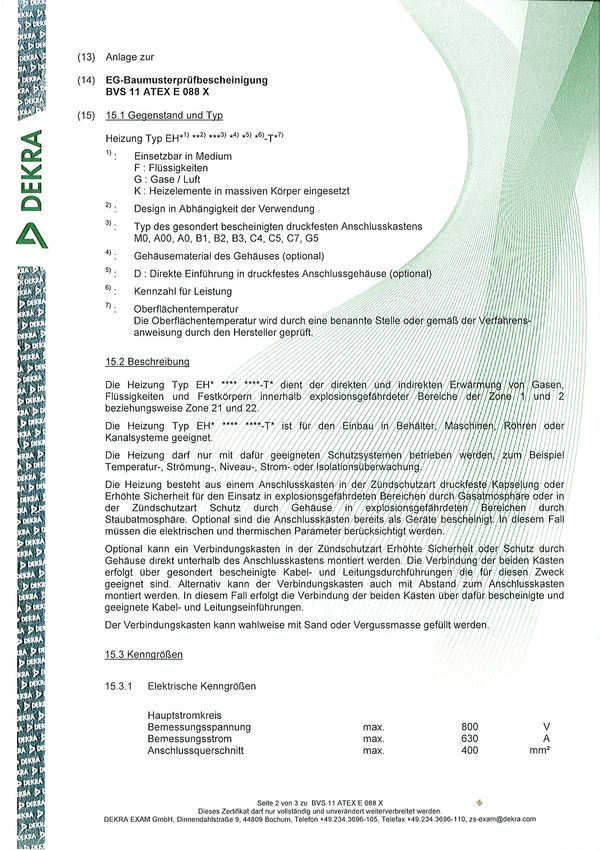
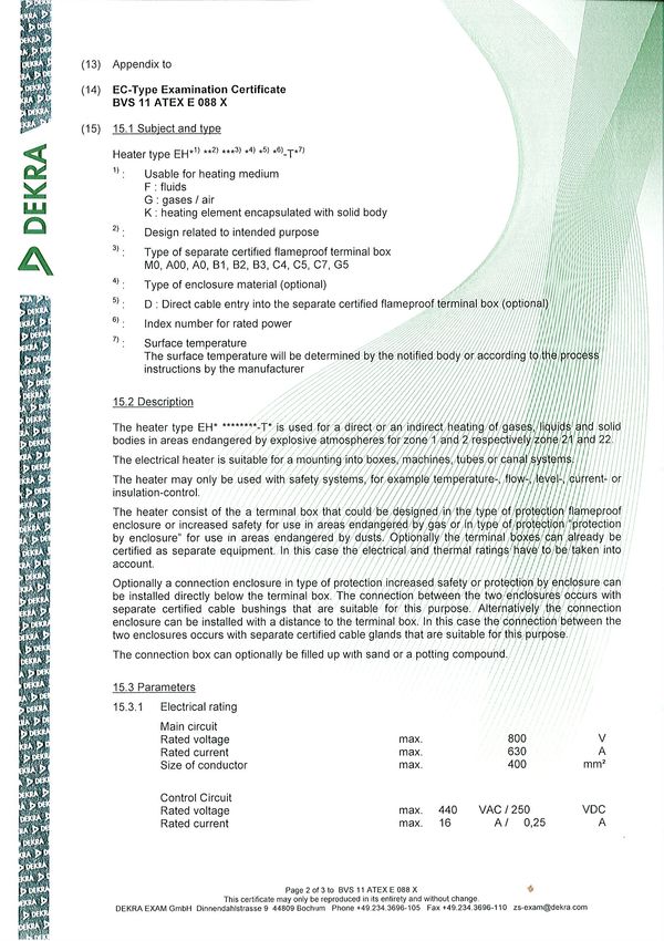
2. EG-Baumusterprüfbescheinigung BVS 11 ATEX E 088 X 6
Ex-Type Examination Certificate
N:\Auftragsdoku\Angebote\10140000 - 10144999\10144700 - 10144799\10144796\Inhaltsverzeichnis_9,0 kW.doc
06.05.2020 Fr
Betriebsanleitung / Operating manual

Heizlüfter                                       Typ EHG../HRV… ; EHG../HRG…
Die Betriebsanleitung besteht aus                - Beschreibung Heizlüfter mit
                                                   EU Konformitätserklärung
                                                 - Spezifikation
                                                 - Maßbild
                                                 - Anschlussschaltbild
                                                 - Betriebsanleitung Ventilator bzw. Gebläse mit
                                                   EU/EG Baumusterprüfbescheinigung

Air Blower Heater                                Type EHG../HRV… ; EHG../HRG…
The operating manual consists of                 - Description of Air Blower Heater together with
                                                   EU Declaration of Conformity
                                                 - Specification
                                                 - Dimensional drawing
                                                 - Wiring diagram
                                                 - Operating Manual for fan resp. blower together with
                                                   EU/EC Type Examination Certificate

Anschrift des Herstellers / Manufacturer:
ELMESS Thermosystemtechnik GmbH & Co. KG
Nordallee 1
29525 Uelzen
e-Mail: et@elmess.de  Tel.: +49 581 9083-0
www.elmess.de         Fax: +49 581 908344

Betriebsanleitung EHG_HR.-DE-EN_Rev-25-03-2019
Beschreibung Heizlüfter /
Description of Air Blower Heater

Inhalt
   1. Aufbau und bestimmungsgemäße Verwendung .......................................................................
  2. Bedingungen für den sicheren Betrieb des Heizlüfters, Allg. Sicherheitshinweise ......................
   3. Montage, Installation und Inbetriebnahme..............................................................................
   4. Einstellungen ..........................................................................................................................
   5. Wartung, Austausch von Ersatzteilen und Störfall ....................................................................
   6. Entsorgung. ............................................................................................................................

1. Aufbau und bestimmungsgemäße Verwendung
Der Heizlüfter ist in explosionsgeschützter Ausführung für den Betrieb in Kategorie                                      II 2 G gebaut.

Der Heizlüfter ist eine Baugruppe aus einem Heizregister und einem Ventilator und dient zur Erwärmung
von Luft innerhalb der Kategorie 2 G.

Der Heizlüfter muss für die Anwendung geeignet sein und darf nur bestimmungsgemäß verwendet
werden.

Der Betrieb des Heizlüfters ist nur unter Anwendung eines auf die zuverlässige Funktion beurteilten
Schutzsystems zulässig.

Das Schutzsystem besteht mindestens aus einem auf die zuverlässige Funktion beurteilten
Temperaturbegrenzungssystem und einem zertifizierten Motorschutz (Motorschutzrelais und
Kaltleiterüberwachungsrelais).

Vom Hersteller eingebaute Kapillarrohrfühler mit Schaltkontakt bzw. Temperaturfühler zusammen mit
dem mitgelieferten elektronischen Schutz-Temperatur-Begrenzer Typ eB*6*** sind entsprechend ATEX
Richtlinie geprüft und geeignet.
Alle Überwachungsgeräte müssen durch andere Schutzgeräte, z.B. Sicherungen und Schaltschütze,
Isolationsfehlerüberwachungseinrichtungen zu einem kompletten Schutzsystem ergänzt werden. Ein
Ansprechen einer oder mehrerer Schutzeinrichtungen muss direkt und zwangsweise zu einem
potentialfreien Trennen des Heizlüfters vom Netz führen.
Zusätzlich kann der Heizlüfter mit anderen Temperaturbegrenzungs- oder Regeleinrichtungen bzw.
Temperaturmessfühlern ausgerüstet sein. Dienen diese Geräte ebenfalls zur Überwachung des
Heizlüfters, sind sie in das Schutzsystem zu integrieren.
Die gelieferte Heizung wurde entsprechend dem Typ geprüft. Veränderungen an der Konstruktion oder
Betriebsbedingungen können eine erneute Prüfung erfordern.
Warnhinweis:
Während des Betriebes können an den Oberflächen der Heizung hohe Temperaturen auftreten.
Durch geeignete Maßnahmen bauseits, ist auf die Verbrennungsgefahr hinzuweisen bzw. die
Verbrennungsgefahr ist durch Dämmung der Heizung zu verhindern. Die der Betriebsanleitung
beiliegenden Warnschilder „Vorsicht heiße Oberfläche“ sind vor der Inbetriebnahme sichtbar am Gerät
anzubringen.

ELMESS-Thermosystemtechnik GmbH & Co. KG
Betriebsanleitung EHG_HR.-DE-EN_Rev-25-03-2019                                                                                     Seite / Page 1
Beschreibung Heizlüfter /
Description of Air Blower Heater
2. Bedingungen für den sicheren Betrieb des Heizlüfters -
Allgemeine Sicherheitshinweise
Die in der EG-Baumusterprüfbescheinigung und Betriebsanleitung des Ventilators genannten
besonderen Bedingungen sind zu beachten.
Die Spaltweite zwischen Flügelrad und Wand des Ventilators ist regelmäßig zu kontrollieren.
Der Ansaugbereich des Heizlüfters muss frei von Hindernissen sein. Die maximale
Ansaugtemperatur des Heizlüfters beträgt plus 40 °C
Beim Betrieb des Heizlüfters ist eine ungehinderte und gleichmäßige Wärmeabgabe
sicherzustellen. Die Ausblasjalousie muss mindestens teilweise geöffnet sein.
Der Betrieb der Heizung ist nur mit Lüfter erlaubt. Auf ausreichenden Nachlauf des Lüfters beim
Abschalten der Heizung ist zu achten.
Der Heizlüfter ist entsprechend der auf dem Maßbild angegebenen Gebrauchslage und unter
Beachtung der Strömungsrichtung zu betreiben.
Die thermische Stückprüfung zur Festlegung der Temperaturklasse erfolgt durch den Hersteller.
Die eingesetzten Sicherheitseinrichtungen für die Temperaturbegrenzung, Überwachung der
Strömung müssen für diesen Zweck geeignet und bescheinigt sein.
Die Heizung ist nur in der vorgegebenen Gebrauchslage und in dem vorgegebenen
Umgebungstemperaturbereich zu betreiben.
Die Anordnung der Temperaturfühler der Temperaturbegrenzer muss einen Phasenausfall mit
einschließen.
3. Montage, Installation und Inbetriebnahme
Wird der Heizlüfter nicht sofort errichtet und betrieben, sind die jedem Heizlüfter beiliegenden
Lagerungsvorschriften zu beachten. Besonders ist die Heizung vor eindringender Feuchtigkeit zu schützen.
Für die Errichtung und Installation ist für diese Kategorie geeignetes Material zu verwenden.
Für die Errichtung, Installation und den Betrieb sind die jeweils gültigen Vorschriften z.B. DIN IEC 60364 zu
beachten. Es gelten die Normen IEC/EN 60079-14, IEC/EN 60079-17 und in Europa die europäischen
Richtlinie 1999/92/EG. In Deutschland gelten zusätzlich die Ex-Regeln der Berufsgenossenschaft Chemie
sowie die Betriebssicherheitsverordnung.
Die Aufstellung/Errichtung des Heizlüfters muss gemäß den Angaben auf dem Maßbild und geschützt vor
direkter Sonneneinstrahlung erfolgen. Besonders ist auf die vorgegebene Gebrauchslage zu beachten.
Der Heizlüfter ist für eine senkrechte Wandmontage durch 2 U-Profilhalterungen vorbereitet. Nach
erfolgter Montage muss der Ventilator unten am Heizlüfter mit den 6 beiliegenden Schrauben fest mit
dem Heizlüfter verbunden werden.
ELMESS-Thermosystemtechnik GmbH & Co. KG
Betriebsanleitung EHG_HR.-DE-EN_Rev-25-03-2019 Seite / Page 2
Beschreibung Heizlüfter /
Description of Air Blower Heater

Die elektrische Installation muss mit fest verlegten Kabeln bzw. Leitungen entsprechend harmonisierter
Normen mit dem der Leistung entsprechenden Querschnitt auf die im Anschlussgehäuse vorgesehenen
Klemmen unter Einhaltung von mindestens 12 mm Luftstrecke erfolgen. Die Heizlüfter sind mit der
entsprechenden Vorsicherung zu sichern.

Für jede eingeführte Leitung ist ein Schutzleiteranschluss vorhanden, der angeschlossen werden muss.

Nicht verwendete Kabeleinführungen bzw. Öffnungen müssen entsprechend IEC/EN 60079-14
verschlossen werden.

Am Heizlüfter sind außen Potenzialausgleichsklemmen in der Zündschutzart Ex e vorhanden, mit der der
Heizlüfter in den äußeren Potenzialausgleich eingebunden werden muss.

4. Einstellungen
Der Abschaltstrom des Motorschutzrelais ist entsprechend des Typschildes des Lüftermotors in
Zündschutzart Ex e einzustellen.

5. Wartung, Austausch von Ersatzteilen und Störfall
Die Wartung der Heizung hat regelmäßig entsprechend IEC EN 60079-17 durch fachkundiges Personal
unter dessen Verantwortung zu erfolgen.
Die Wirksamkeit des Schutzsystems ist bei der Inbetriebnahme und danach im Rahmen der
wiederkehrenden Anlagenprüfungen, spätestens jedoch alle drei Jahre, zu überprüfen.
Von außen sichtbare Beschädigungen bzw. Korrosion an Gehäuseteilen sowie an Anschlussteilen sind
umgehend mit Originalersatzteilen durch den Hersteller, die Firma ELMESS-Thermosystemtechnik GmbH
& Co. KG, Nordallee 1, D-29525 Uelzen, oder durch fachkundiges Personal (IEC EN 60079-19, Anhang B)
unter dessen Verantwortung nach Montageanleitung zu beheben.
Es dürfen nur Originalersatzteile des Herstellers verwendet werden.

6. Entsorgung
Die Heizung und der Ventilator müssen getrennt und unter Beachtung der Vorschriften für Sondermüll
entsorgt werden. Es sind mehrfach wiederverwertbare Stoffe enthalten.

Weitere Information unter www.elmess.de

ELMESS-Thermosystemtechnik GmbH & Co. KG
Betriebsanleitung EHG_HR.-DE-EN_Rev-25-03-2019                                              Seite / Page 3
Beschreibung Heizlüfter /
Description of Air Blower Heater

Übersetzung, Original Deutsch; Translation, original German

Table of content
   1. Design and proper use ............................................................................................................
   2. Conditions for safe operation of the Air Blower Heater, general safety instructions ..................
   3. Mounting, installation and commissioning...............................................................................
   4. Adjustments ...........................................................................................................................
   5. Maintenance, exchange of spare parts and malfunctions .........................................................
   6. Disposing ................................................................................................................................

1. Design and proper use
The Air Blower Heater is manufactured in explosion proof design for operation in category                                              II 2 G.

The Air Blower Heater is manufactured as an assembly of a heater and a fan and serves for heating air
within category 2 G.

The Air Blower Heater must be suitable for the specified application and may only be used in a manner
appropriate to its purpose.

It is only permitted to operate the Air Blower Heater in conjunction with a safety system acknowledged
to be reliable in its function.

The safety system must consist of at least one temperature limiting system, which all have been
successfully acknowledged to be reliable together with a certified engine protection (protection relay
and thermistor monitoring device).

Capillary temperature probes with a switching contact installed by the manufacturer or temperature
sensors, together with the delivered thermal cut-out type eB*6*** have been inspected and approved
according to ATEX directive. All monitoring devices must be fitted with other protective devices, e.g. fuses
and relays, contactors, RCD’s to form a complete safety system. Should one or more of the safety devices
be activated, the heater must, without exception, be immediately physically disconnected from the
electrical mains supply.
The Air Blower Heater can also be fitted with other temperature limiters, regulators or temperature
sensors. If these devices are also to be used for monitoring purposes, they shall be integrated into the
safety system.
The delivered heater is tested according the type. Any change of construction or operating conditions may
the type test necessary once more.
Warning:
At heater surfaces high temperatures occur during operation.
By appropriate measure on site, the risk of burning is to indicate, respectively the risk of burning is to
prevent by insolation the heater. Two signs “Caution hot surface”, attached at the operating manual,
must placed visible at the device, before put into operation.
ELMESS-Thermosystemtechnik GmbH & Co. KG
Betriebsanleitung EHG_HR.-DE-EN_Rev-25-03-2019                                                                                       Seite / Page 4
Beschreibung Heizlüfter /
Description of Air Blower Heater
2. Conditions for safe operation of the Air Blower Heater –
General Safety Instructions
The special conditions named in the EC Type Examination Certificate and operating manual for the
fan must be observed.
The gap between fan wheel and wall of fan must be checked regularly.
The inlet of the Air Blower Heater must be free of any kind of barrier. The maximum of input
temperature must not exceed 40 °C.
It should be ensured that the heat emission is evenly distributed and not obstructed during
operation. The outlet shutter must be open, at least partially open.
Operation of heater is only permitted together with fan. A delay for switch off of fan after trip of
heater must be secured.
The Air Blower Heater may only be operated in position according dimension sheet and by
observing the flow direction.
The individual thermal test to determine the temperature class is to be carried out by the
manufacturer.
The used safety devices for limiting the temperature, monitoring the flow rate have to be suitable
for this purpose and have to be certified.
The heater with flow rate monitoring may only be used when the flow rate is above the minimum
flow rate that was mentioned in the specification.
It should be ensured that the heat emission is evenly distributed and not obstructed during
operation.
The positioning of the temperature sensors for the temperature limiter has to be carried out in
such a way, that a failure of one phase is included.
3. Mounting, installation and commissioning
If the Air Blower Heater is not to be immediately fitted and operated, the storage instructions included
with every heater delivery must be observed. The heater must be protected from damp entering the
device in particular.
Material appropriate to the category is to be used when fitting and operating the device.
Applicable regulations, e.g. DIN IEC 60364 must be observed when fitting, installing and operating the
device. Following standards IEC/EN 60079-14, IEC/EN 60079-17 and in Europe the EC directive
1999/92/EC must apply. Furthermore, local regulations, such as the explosion protection regulations of
the Chemical Industry Employer's Liability Insurance Association and the Ordinance on Industrial Safety
and Health for Germany, have to be observed.
ELMESS-Thermosystemtechnik GmbH & Co. KG
Betriebsanleitung EHG_HR.-DE-EN_Rev-25-03-2019 Seite / Page 5Beschreibung Heizlüfter / Description of Air Blower Heater The erection of the Air Blower Heater has to occur in accordance with the dimensional drawing and to be protected against solar radiation. Especially the mounting position has to be considered. The Air Blower Heater is prepared for a vertical mounting by 2 U-profil holdfasts. After mounting the Air Blower Heater at a wall, the fan must be tight mounted at the botton side of Air Blower Heater by 6 attached screws. The electrical installation must be done on terminal box by using fix connected wiring, which meets harmonised standards, with a cross-section appropriate to the power rating on the matching terminals and concerning a 12 mm air distance in between. The heater must be protected with an appropriate back- up fuse. For each cable leading must be an earth conductor, which must be connected. Cable entries respectively open holes, which are not used, must be safely shut in accordance to IEC/EN 60079-14. The potential equalisation terminals with type of protection Ex e are available on the exterior of casing, to which the Air Blower Heater must be connected with the external potential equalisation source. 4. Adjustments The trip current of engine protection relay must be adjusted according the value at name plate of fan with type of protection Ex e. 5. Maintenance, exchange of spare parts and malfunctions The heater must be maintained in accordance with IEC EN 60079-17 by and in responsibility of qualified personnel. The efficiency of the protecting system must be examined when commissioning the device and thereafter with the repeating system checks, latest every 3 years. Externally visible damage or corrosion of components of the flame proof enclosure or of connector components must be repaired immediately using genuine spare parts by the manufacturer, ELMESS- Thermosystemtechnik GmbH & Co. KG, Nordallee 1, D-29525 Uelzen, Germany, or by qualified personnel (IEC EN 60079-19, app. B) at its responsibility acc. to mounting instructions. Only genuine spare parts of manufacturer may be used. 6. Disposing The heater unit and the fan must be removed and handled in compliance with the District Council. Inside are several parts of recyclable materials. Further information available under www.elmess.de ELMESS-Thermosystemtechnik GmbH & Co. KG Betriebsanleitung EHG_HR.-DE-EN_Rev-25-03-2019 Seite / Page 6
Heizregister                                                        Spezifikation
Kunde                              Malux Sweden AB                              Datum                  04.05.2020                                 Rev00
Fabrik Nr.                         000000 / 001                                 Anzahl                 1
Auftrag Nr. / Position             000000 - 0010                                Kunden
Artikel Nr.                        5006…                                        Angaben
Bezeichnung                        Ex-Heizregister                              Typ                    EHG11/HR-9-T3 *)

1 Schutzart IEC/EN 60529                                     IP 66
2 Ex-Kennzeichnung Zündschutzart
   IEC/EN 60079                                              (Ex) II 2G Ex e IIC T3
   IEC/EN 60079-31
  EG-Baumusterprüfbescheinigung | IECExZertifikat            BVS 11 ATEX E 088 X                                          ----
   EU Konformitätserklärung          ( für die Baugruppe )   ELM 16-009
3 Elektrische Daten und Anschluss
   Leistungsgruppen                                    E1    Gesamt
   Bemessungsleistung                                        9,0 kW
   Bemessungsstrom                                           13 A
   Vorsicherung                                              16 A
   Bemessungsspannung                                        400 V 3/PE 50 Hz
   Spezifische Oberflächenbelastung                          0,4 W/cm²
   Steuerstromkreis Temperaturüberwachung                    max. 10 A; 230 V 1/N/PE 50 Hz
   Steuerstromkreis weitere Überwachungsgeräte               ----
   Gehäuseheizung                                      E2    ----
   Anschlussschaltplan                                       16-1656-40
   Anschlussquerschnitt Laststromkreis                       4 mm²
   Anschlussquerschnitt Steuerstromkreis                     max. 4 mm²
   Kabeleinführung Laststromkreis / Material                 1x M25x1,5; für Kabel-ø 9…17 mm / PA                     Anzugsdrehmoment: 5,5 Nm
   Kabeleinführung Laststromkreis / Material                 ----
   Kabeleinführung Steuerstromkreis / Material               1x M25x1,5; für Kabel-ø 9…17 mm / PA                     Anzugsdrehmoment: 5,5 Nm
   Kabeleinführung Gehäuseheizung / Material                 ----
4 Schutzsystem
   Temperaturüberwachung                               B1    TB = T3 - wirksam auf Heizelementoberfläche

  Isolations- bzw. Fehlerstromüberwachung                    min. 50 Ω pro Volt bzw. max. 100 mA
  Strömungsüberwachung                                 B3    nicht erforderlich

  weitere Überwachungsgeräte bzw. Sensoren
  Temperatur Wächter, Regler                           B2    TR = 0…200 °C - wirksam auf Heizelementoberfläche

  Temperatur Wächter, Regler                           B4    ----

5 Abmessungen
   Massblatt / Zeichnung                                     000000
   Lichte Kanalabmessung Höhe H + H1                         260 / 335 mm
   Lichte Kanalabmessung Breite B + B1                       260 / ~485 mm
   Lichte Kanalabmessung Tiefe T + T1                        1190 / 1420 mm
   Flanschrahmenbreite                                       18 mm
   Angaben Bohr- / Schaltschema                              000000
   Blechverkleidung nach Zeichnung                           09-009-30
   Flanschplatte nach Zeichnung                              21-
6 Werkstoffe / Oberfläche
   Heizbündel                                                1.4541                                    metallisch blank
   Strömungskanal                                            1.4301                                    metallisch blank
   Flanschrahmen                                             1.4301                                    metallisch blank
   Gehäuse                                                   1.4301                                    metallisch blank
7 Betriebsdaten
   Medium / Volumenstrom                                     Luft                                      / max. 1000 m³/h i.N.
   Austrittstemperatur                                       max. 60 °C
   Temperaturerhöhung                                        ~ 18 K
   Umgebungstemperatur / max. Gehäuseinnentemp.              -20 ... +40 °C    / 60 °C
   Einbau                                                    im Aggregat, Tank oder Behälter; Einbaulage waagerecht;
                                                             Kabeleinführung rechts; H 90, V 90
8 Auslegungsdaten
   Auslegungscode                                            ----
   Maximal zulässiger Betriebsüberdruck (PS)                 ----
   Zulässige Temperatur min. / max. (TS)                     ----
   Fluidgruppe / Diagramm                                    ----
   Kategorie / Modul                                         ----
   Abnahme / Zeugnis / Protokoll                             ---- / ----                            / 000000 - 0010
9 Dokumentation
   Sprache                                                   deutsch                     /              englisch                    /             ----
   Betriebsanleitung                                         EHG../HRV…; EHG../HRG…
10 Bemerkungen                                               *) komplettiert zur Baugruppe Ex-Heizlüfter Typ: EHG11/HRV-9-T3
                                                             mit eingebautem Ex-Ventilator Fabrikat MAICO Typ: DZR 20/2 B E Ex e,
                                                             65 W / 0,23 A / Lwa5 = 80 dB(A) / IP 54, 2950 U/min / 1150m³/h frei blasend;
                                                             EG Baumusterprüfbescheinigung EX5 03 06 39250 007
11 Interne Angaben
  RHK: Anzahl Form; Schaltung; Typ                           30 DW; YP; NR 199V 5G / 200W / 230V
  Lot / Schweißzusatz / RHK-ø                                A 314 / 1.4576 / 8,5 mm
  Projektleiter / Sachbearbeiter                             Hr. Lemmermann                     Hr. Büthe

\\Elmess-file02\et\Auftragsdoku\Angebote\10140000 - 10144999\10144700 - 10144799\10144796\9,0 kW.xlsm                                            04.05.2020
Heating Coil Specification
Translation, Original German
Client Malux Sweden AB Date 04.05.2020 Rev00
Fabric No. 000000 / 001 Piece 1
Order No. / Position 000000 - 0010 Client details
Article No. 5006…
Name Ex-Heating coil Type EHG11/HR-9-T3 *)
1 Degree of Protection IEC/EN 60529 IP 66
2 Ex Marking and Type of Protection
IEC/EN 60079 (Ex) II 2G Ex e IIC T3
IEC/EN 60079-31
EC Type Examination Certificate | IECEx Certificate BVS 11 ATEX E 088 X ----
( for the module
EU Declaration of Conformity ELM 16-009
)
3 Electrical data and connection
Power groups E1 Complete
Rated power 9,0 kW
Rated current 13 A
Back up fuse 16 A
Rated voltage 400 V 3/PE 50 Hz
Specific surface load 0,4 W/cm²
Control circuit temperature monitoring max. 10 A; 230 V 1/N/PE 50Hz
Control circuit additional monitoring devices ----
Anti condensation heater E2 ----
Connection diagramm 16-1656-40
Connection cross section power circuit 4 mm²
Connection cross section control circuit max. 4 mm²
Cable entry power circuit / material 1x M25x1,5; for cable-ø 9…17 mm / PA tightening torque: 5,5 Nm
Cable entry power circuit / material ----
Cable entry control circuit / material 1x M25x1,5; for cable-ø 9…17 mm / PA tightening torque: 5,5 Nm
Cable entry anti condensation heater / material ----
4 Protection system
Temperature monitoring B1 TL = T3 - effective on heating element surface
Isolation resp. residual current device min. 50 Ω per voltage resp. max. 100 mA
Flow monitoring device B3 not necessary
Additional monitoring devices or sensors
Temperature monitor, regulators B2 TR = 0…200 °C - effective on heating element surface
Temperature monitor, regulators B4 ----
5 Dimensions
Dimension sheet / drawing 000000
Duct dimensions height H + H1 260 / 335 mm
Duct dimensions width B + B1 260 / ~485 mm
Duct dimensions depth T + T1 1190 / 1420 mm
Flange frame width 18 mm
Intern. data: drill / wiring diagramm 000000
Sheet covering accord. to drawing 09-009-30
Flange plate accord. to drawing 21-
6 Material & Surface
Heating elements 1.4541 metallic bright
Flow channel 1.4301 metallic bright
Flange frame 1.4301 metallic bright
Connection enclosure 1.4301 metallic bright
7 Operation data
Medium / flow rate Air / max. 1000 m³/h i.N.
Temperature out max. 60 °C
Increase of temperature ~ 18 K
Ambient temperature / max. housing temperature -20 ... +40 °C / 60 °C
Mounting position in aggregate, tank or container; Heater horizontal;
cable glands from right hand side; H 90, V 90
8 Design data
Design code ----
Allowable operating pressure ----
Allowable temperature min. / max. ----
Fluid group / diagramm ----
Category / module ----
Inspection / certificate / report ---- / ---- / 000000 - 0010
9 Documentation
Language german / english / ----
Operation manual EHG../HRV…; EHG../HRG…
10 Remarks *) assambled to module Ex-fan heater type: EHG11/HRV-9-T3
with Ex-fan fabrication MAICO Type: DZR 20/2 B E Ex e;
65 W / 0,23 A / Lwa5 = 80 dB(A) / IP 54; 2950 U/min / 1150 m³/h free blowing;
Ex Type Examination Certificate EX5 03 06 39250 007
11 Internal remarks
Heating elements: pieces; shape; wiring; type 30 DW; YP; NR 199V 5G / 200W / 230V
Solder / welding filler / heating elements diameter A 314 / 1.4576 / 8,5 mm
In charge / Project team Mr. Lemmermann Mr. Büthe
\\Elmess-file02\et\Auftragsdoku\Angebote\10140000 - 10144999\10144700 - 10144799\10144796\9,0 kW.xlsm 04.05.2020Elektrische Schaltung Heizung
Electrical diagram heater
Typ / Type EHG11/HR-9-T3 *)
Bemessungsleistung / Rated power 9,0 kW Auftrag Nr. / Order No. 000000 - 0010
Bemessungsspannung / Rated voltage 400 V 3/PE 50 Hz Kunde / Customer Malux Sweden AB
Bemessungsstrom / Rated current 13 A Schaltplan-Nr. / Diagram No. 16-1656-40
Vorsicherung / Back up fuse 16 A
Klick für Anschlussschaltbild
Ex-Heizregister TB = T3 - wirksam auf TR = 0…200 °C - wirksam auf Lüfter MAICO Typ: DZR 20/2 B E Ex e,
Heizelementoberfläche Heizelementoberfläche 65 W / 0,23 A / Lwa5 = 80 dB(A) / IP 54, 2950 U/min
Ex-Heating coil TL = T3 - effective on heating element TR = 0…200 °C - effective on heating element Fan MAICO Type: DZR 20/2 B E Ex e;
surface surface 65 W / 0,23 A / Lwa5 = 80 dB(A) / IP 54; 2950 U/min
\\Elmess-file02\et\Auftragsdoku\Angebote\10140000 - 10144999\10144700 - 10144799\10144796\9,0 kW.xlsm 04.05.2020Sie können auch lesen


