DYC-817 3.0 Dynamikkompressor Bauanleitung - Hocheffizienter externer Dynamikkompressor mit dem SSM2167 von Analog Devices für die ...
←
→
Transkription von Seiteninhalten
Wenn Ihr Browser die Seite nicht korrekt rendert, bitte, lesen Sie den Inhalt der Seite unten
Dynamikkompressor
DYC-817                          3.0
Hocheffizienter externer Dynamikkompressor
mit dem SSM2167 von Analog Devices für die
Yaesu-Transceiver FT-817 bzw. FT-818

Bauanleitung
The kit for this dynamic compressor was
Construction Manual for DYC-817                                             originally introduced in [1] based on an
                                                                            idea of Phil Salas, AD5X. It was develo-
Dynamic Compressor V3.0 for FT-817/818                                      ped especially for the FT-817 (now FT-
                                                                            818), but can also be used for other trans-
                                                                            ceivers with the same microphone interfa-
                                                                            ce, such as the FT-857, FT-897, FT-900 or
                                                                            FT-991. But never use the external com-
                                                                            pressor in combination with the internal of
                                                                            a transceiver!
When transmitting SSB, a dynamic compressor increases average trans-
mitted power, and thus the audibility of a weak signal at the distant re-

                                                                            The dynamic compressor is plugged in
ceiver, by at least one S-unit. This accessory is of special interest to

                                                                            between the microphone and the transcei-
amateur radio operators who work with lower transmitting power or wish

                                                                            ver. It does not require a separate power
to be better heard in a pile-up.

                                                                            supply, and can be switched on or off as
                                                                            needed. No modifications to the original
                                                                            microphone or to the transceiver are requi-
                                                                            red.

                                                                            The integral AF tone generator, which fa-
                                                                            cilitates antenna tuning in SSB mode, can
                                                                            be keyed via two existing buttons on the
                                                                            microphone. As a result, the general prac-
                                                                            tice of whistling for tuning is no longer re-
                                                                            quired.

                                                                            With the exception of one tantalum capa-
                                                                            citor, the SMD components are preassem-
                                                                            bled. Only a few wired components re-
                                                                            main; these can be easily installed even by
                                                                            less experienced builders.

2 • BX-817-3                                                                © Box 73 Amateurfunkservice GmbH 2018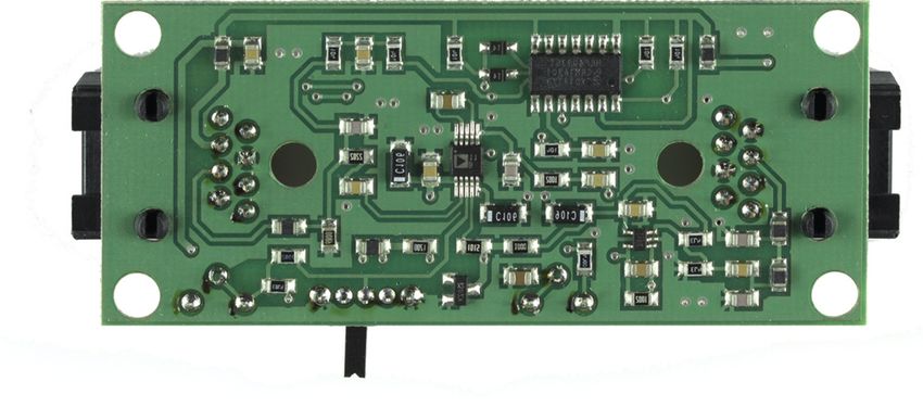
Der Bausatz basiert auf einer Idee von Phil
Bauanleitung zum Dynamikkompressor Salas, AD5X, und wurde ursprünglich in
[1] vorgestellt. Er war seinerzeit speziell
DYC-817 Vers. 3.0 für FT-817 und FT-818 für den FT-817 (jetzt FT-818) konzipiert,
ist aber auch an anderen Transceivern ver-
wendbar, die über die gleiche Mikrofon-
schnittstelle verfügen, wie z. B. FT-857,
FA-Leserservice
FT-897, FT-900 oder FT-991 und kann
ggf. alternativ (niemals in Kombination)
Ein Dynamikkompressors erhöht bei der Sendeart SSB die durchschnitt-
zum eingebauten Sprachprozessor dieser
Transceiver benutzt werden.
liche Sendeleistung und damit die Verständlichkeit eines schwachen
Empfangssignals um mindestens eine S-Stufe. Damit ist dieses Zusatz-
Der Dynamikkompressor wird in die Lei-
gerät speziell für Funkamateure interessant, die mit kleiner Sendeleis-
tung zwischen Mikrofon und Transceiver
tung arbeiten oder im Pile-up besser gehört werden wollen.
eingeschleift, benötigt keine separate
Stromversorgung und ist bei Bedarf zu-
oder abschaltbar. Modifikationen am Ori-
ginalmikrofon oder am Transceiver sind
nicht erforderlich.
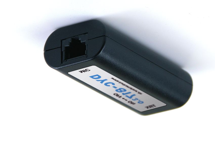
Bild 1:
Der integrierte NF-Generator lässt sich
Dynamikkompressor
mithilfe zweier Tasten am Mikrofon zu-
im fertig aufgebauten
schalten und erleichtert auf diese Weise
und einsatzbereiten
Zustand
das Abstimmen der Antenne in der Sende-
art SSB. Das oft praktizierte Abstimm-
Pfeifen wird damit überflüssig.
Die SMD-Bauelemente sind, bis auf einen
Tantal-Elko, bereits vorbestückt. Es blei-
ben somit nur noch einige bedrahtete Bau-
teile übrig, die sich auch von weniger ge-
übten Bastlern einfach verarbeiten lassen.
Figure 1:
A dynamic compres-
sor, fully assembled
and ready to use
© Box 73 Amateurfunkservice GmbH 2018 BX-817-3 • 3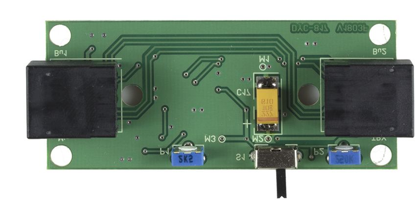
■ Circuit

Figure 2 shows the AF dynamic compres-
sor’s schematic. Its central feature is the
special Analog Devices SSM2167 micro-
phone preamplifier. This IC has a fixed
gain of 18 dB, which is compensated for
by the R14/R18 voltage divider.
The adjustment resistor P1 in the negative
feedback branch of the low-noise pream-
plifier IC1 serves to raise the level of the
microphone signal until it exceeds the no-
ise gate of the SSM2167. Quiet (distur-
bing) noises can be effectively suppressed
in this way.
 The Switch S1is used to turn the compres-
sor function on and off, and along with po-
tentiometer P2 sets the desired compres-
sion ratio. Three of the four NAND gates
on CMOS chip IC2 form the AF generator,
which can be activated by simultaneously
pressing the PTT and Down microphone
buttons.

The compressor is powered from the inter-
nal 5V DC rail of the connected transcei-
ver. Current consumption is approximate-
ly 10 mA.                                      Figure 2:
                                               Schematic
                                               DYC-817-3

4 • BX-817-3                                               © Box 73 Amateurfunkservice GmbH 2018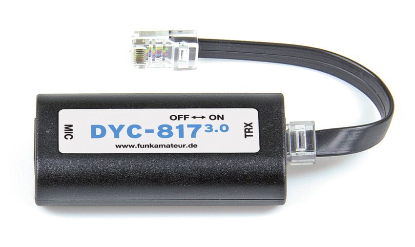
■ Schaltung

                                                                 In Bild 2 ist die Schaltung des neuen NF-
                                                                 Dynamikkompressors zu sehen. Die Über-
                                                                 arbeitung machte sich erforderlich, da der
                                                                 bisher eingesetzte SSM2165P von Analog
                                                                 Devices nicht mehr verfügbar ist.
                                                                 Herzstück ist nunmehr der SSM2167. Er
                                                                 hat eine Grundverstärkung von 18 dB, die
                                                                 mit dem Spannungsteiler R14/R18 kom-
                                                                 pensiert wird. Der Einstellwiderstand P1
                                                                 im Gegenkopplungszweig des NF-Vorver-
                                                                 stärkers IC1 dient dazu, den Pegel des
                                                                 Mikrofonsignals so weit anzuheben, bis er
                                                                 die Ansprechschwelle (Noise Gate) des
                                                                 SSM2167 überschreitet. Leise (Stör-)Ge-
                                                                 räusche lassen sich auf diese Weise wirk-
                                                                 sam unterdrücken.
                                                                 Der Schiebeschalter S1 dient zum Ein-
                                                                 und Ausschalten der Kompressorfunktion
                                                                 und mit dem Einstellwiderstand P2 kann
                                                                 man das Kompressionsverhältnis einstel-
                                                                 len.
                                                                 Drei der vier NAND-Gatter des CMOS-
                                                                 Schaltkreises IC2 bilden den NF-Genera-
                                                                 tor, der durch gleichzeitiges Drücken der
                                                                 Mikrofontasten PTT und Down aktiviert
                                                                 werden kann.
                                                                 Ihre Betriebsspannung von 5 V bezieht die
                                                                 Schaltung vom Transceiver, die Stromauf-
                                        Bild 2: Schaltplan des

                                                                 nahme beträgt etwa 10 mA.
                                        Dynamikkompressors
                                        DYC-817-3

© Box 73 Amateurfunkservice GmbH 2018                                                        BX-817-3 • 5
■ Construction

After checking all parts against the parts     sary in order to facilitate soldering the ca-
list, you may begin assembly of the circuit    pacitor. Next, heat the previously tinned
board. You will need a temperature-con-        solder pad with a soldering iron and, in
trolled low-voltage soldering iron, 1 mm       this way, “tack” it to the capacitor. If the
dia. rosin-cored solder, a pair of tweezers    capacitor is sitting incorrectly, it can still
and a small pair of wire-cutters.              be straightened at this stage. If everything
                                               fits, solder the negative pole and subse-
Warning! When working on the board, be         quently, the positive pole.
sure that it is not exposed to undue mecha-
nical stress. Strong pressure, which causes    This is followed by the two potentiometers
transverse deflection on the board, should     P1 (2,5 k) and P2 (250 k) and the miniatu-
be avoided. Lengthwise rotation (torsion)      re slide switch S1. Along with the box, the
should be avoided as well.                     latter should sit flat on the circuit board so
                                               that the horizontal lever later fits through
Both RJ45 sockets are already inserted on      the opening in the box.
the board, so only the eight pins of each
socket need to be soldered to the board        Now, the protruding leads of P1, P2 and
                                               S1 located on the solder side in the imme-
Next, tantalum capacitor C17 is installed.     diate vicinity of the board edge, must be
Its positive pole is marked with a dash,       carefully cut flush with the board using
and its correct positioning can be seen in     wire cutters so that the board fits nicely in-
Figures 3 and 5 of the assembly guide.         to the bottom half of the box when assem-
                                               bled.
When soldering C17, proceed as follows:
First, tin the solder pad of the terminal to
the board. Then, center the capacitor and
its solder connections over the board’s two
solder pads. These have been intentionally
designed to be slightly larger than neces-

6 • BX-817-3                                                                                    © Box 73 Amateurfunkservice GmbH 2018
■ Aufbau
Nach der Prüfung der Vollzähligkeit der
wenigen Bauteile anhand der Stückliste
kann man mit der Bestückung der Platine
beginnen. Dazu werden ein geregelter
Niederspannungslötkolben, 1-mm-Löt-
draht mit Flussmittelseele, eine Pinzette
sowie ein kleiner Seitenschneider benötigt.
Achtung! Bei Arbeiten an der Platine ist
darauf zu achten, dass diese keinen über-
mäßigen mechanischen Belastungen aus-
gesetzt wird. Starker Druck, der zum
Durchbiegen der Leiterplatte in Querrich-
tung führt, ist ebenso zu vermeiden wie
ein Verdrehen in Längsrichtung.
Die beiden RJ45-Buchsen sind bereits auf
die Platine gesteckt, sodass nur noch die
jeweils acht Anschlüsse zu verlöten sind.
Zweckmäßigerweise bestückt man dann
den Tantal-Elektrolytkondensator C17.
Dessen Pluspol ist mit einem Querstrich
gekennzeichnet. Seine korrekte Positio-
nierung ist sowohl im Bestückungsplan
Bild 3 als auch in Bild 5 ersichtlich.
Beim Einlöten von C17 geht man wie
folgt vor: Zuerst wird das Lötpad des Plus-
pols auf der Platine verzinnt. Anschlie-
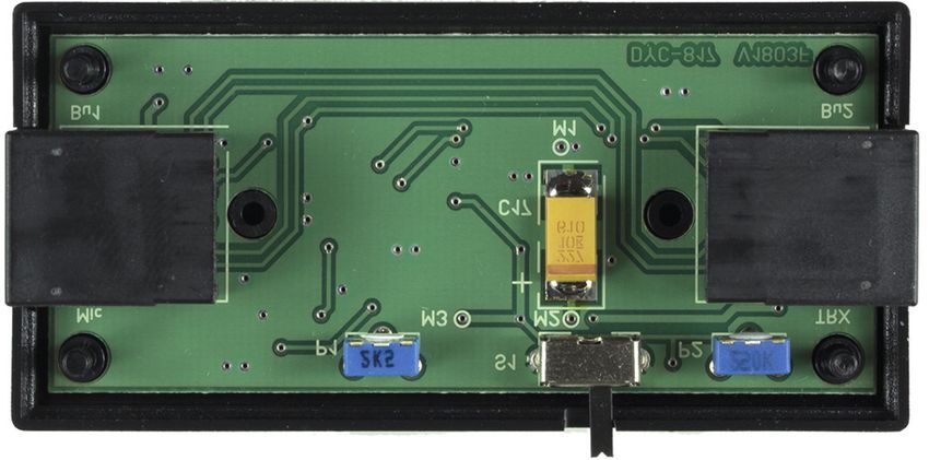
Bild 3: Bestückungsplan des Dynamikkompressors (Oberseite der Platine)
Figure 3: Assembly diagram (PCB, top side)
© Box 73 Amateurfunkservice GmbH 2018 BX-817-3 • 7Bild 4: Bestückungsplan der SMD-Bauelemente (Unterseite der Platine)
Figure 4: Assembly diagram of the preassembled SMD parts (PCB, bottom side)
8 • BX-817-3 © Box 73 Amateurfunkservice GmbH 2018ßend setzt man den Kondensator mit sei-
nen Lötanschlüssen mittig auf die beiden
Lötflächen der Platine. Diese sind absicht-
lich etwas größer als erforderlich dimen-
sioniert, um das Einlöten des Kondensa-
tors zu vereinfachen. Nun wird das zuvor
Bild 5:
verzinnte Lötpad mit dem Lötkolben er-
Vollständig bestückte
wärmt und auf diese Weise der Kondensa-
Platine (Oberseite)
tor „angeheftet“. Falls er doch noch schief
sitzen sollte, lässt sich das jetzt noch kor-
rigieren. Wenn alles passt, lötet man jetzt
den Minuspol an und den Pluspol noch
einmal nach.
Es folgen die beiden unterschiedlichen
Figure 5:
Einstellwiderstände P1 (2,5 k) und P2
Fully assembled
(250 k) sowie der Miniatur-Schiebeschal-
printed circuit board
ter S1. Letzterer sollte mit seinem Gehäu-
(top)
se flach auf der Platine sitzen, damit der
waagerecht liegende Schalthebel später
durch die Öffnung im Gehäuse passt.
Bild 6:
SMD-vorbestückte
Nun sind noch die in unmittelbarer Nähe
Platine (Unterseite-
seite)
des Platinenrandes befindlichen Bauele-
menteanschlüsse von P1, P2 und S1 auf
der Platinenunterseite mit dem Seiten-
schneider vorsichtig zu kürzen, damit die
Platine später gut in die Unterschale des
Figure 6:
Fully preassembled
Gehäuses passt.
printed circuit board
(bottom)
© Box 73 Amateurfunkservice GmbH 2018 BX-817-3 • 9■ Start-Up
Before the compressor is connected to the stage, it can be corrected with P1. Refer to
transceiver for the first time, current con- the guide in the section on operating in-
sumption should be checked. To do this, structions when adjustingthe compression
you will need a 5V laboratory power sup- ratio with P2.
ply and a multimeter with a current mea-
suring range.
The required operating voltage connection To install the unit inside the box, the as-
■ Box installation
can be made with two thin wires provisio- sembled board is placed inside the lower
nally soldered across C17. The multime- half of the shell (Figure 7). The upper half
ter, connected in series, should show a cur- of the shell is placed on the lower half.
rent of about 10 mA. A significantly diffe- Both halves of the box have corresponding
rent value points to an assembly error. Be- sockets and pins to ensure firm cohesion.
fore moving on, it is necessary to find and It is not necessary to affix the board to the
fix this error. Particular attention should box with additional screws. After pressing
be paid to proper mounting and clean sol- the two halves together and applying the
der joints. label, the dynamic compressor is ready for
use (Figure 1).
Warning! If you connect the dynamic
compressor to the transceiver despite ex-
cessive current consumption, the transcei-
ver may be damaged.
Potentiometers P1 and P2 are set at mid-
range from the factory. P1 and P2 already
produce a clearly perceptible effect in this
position. For this reason, the first tests
should be conducted at this setting. If the
microphone level is too high or low at this
10 • BX-817-3 © Box 73 Amateurfunkservice GmbH 2018■ Inbetriebnahme
Bevor der Kompressor zum ersten Mal an Achtung! Sollten Sie den Dynamikkom-
den Transceiver angeschlossen wird, sollte pressor trotz einer möglicherweise zu ho-
man die Stromaufnahme überprüfen. Dazu hen Stromaufnahme an den Transceiver
werden ein 5-V-Labornetzgerät und ein anschließen, kann der Transceiver beschä-
Multimeter mit Strommessbereich benö- digt werden.
tigt. Die Einstellwiderstände P1 und P2 befin-
Der dazu erforderliche Betriebspannungs- den sich bei Auslieferung in Mittelstel-
anschluss kann mit zwei dünnen Drähten lung. Schon so ergibt sich ein deutlich
erfolgen, die man parallel zu C17 proviso- wahrnehmbarer Effekt. Die ersten Tests
risch angelötet. Das in Reihe geschaltete sollte man deshalb auch mit dieser Einstel-
Multimeter sollte einen Strom von etwa 10 lung vornehmen. Wenn sich dabei zeigt,
mA anzeigen. Ein deutlich abweichender dass der Mikrofonpegel zu gering oder zu
Wert weist auf einen Aufbaufehler hin. hoch ist, kann dieser mit P1 korrigiert wer-
Dieser Fehler ist zunächst zu finden und den. Zur Einstellung der Kompression mit
zu beheben. Besonderes Augenmerk ist P2 sind die Hinweise im Abschnitt Be-
dabei auf die korrekte Bestückung und auf triebshinweise zu beachten.
saubere Lötstellen zu legen.
Zum Einbau in das Gehäuse wird die be-
■ Einbau in das Gehäuse
stückte Platine in die Unterschale gelegt
Bild 7:
(Bild 7) und die Oberschale daraufgesetzt.
Gehäuseunterschale
Beide Gehäusehälften verfügen über
mit eingesetzter
Platine
Buchsen und Zapfen, die einen festen Zu-
sammenhalt gewährleisten. Eine Fixie-
rung der Platine mit Schrauben ist nicht
erforderlich. Nach dem Zusammendrü-
cken der beiden Gehäuseschalen und dem
Aufbringen des Aufklebers ist der Dyna-
Figure 7:
mikkompressor einsatzbereit (Bild 1).
Lower part of
the box with inlaid
circuit board
© Box 73 Amateurfunkservice GmbH 2018 BX-817-3 • 11Especially at low SSB signal received
strength, dynamic compression has a po-
■ Operating Instructions
The AF dynamic compressor DYC-817-3 sitive effect on speech intelligibility. Dis-
is looped into the microphone lead of the tant stations will notice a signal strength
original Yaesu MH-31A8J microphone. It increase of about 1 S-unit (6 dB), and the
is not suited for use with the optional increase in loudness may be even higher.
DTMF microphone.
The dynamic compressor should not be
To connect to the transceiver, one of the turned on for FM, as there are no resulting
two plugs on the supplied short cable must benefits. On the contrary, the signal quali-
be inserted into the dynamic compressor’s ty will be degraded on the receiving end.
TRX socket. The other plug must be in- The same applies to SSB paths with good
serted into the transceiver’s microphone audibility. The compressor comes into its
jack. The plug on the microphone cable is own with signals at the limit of audibility.
then inserted into the MIC port on the It should not be turned on in any other ca-
compressor. When the transceiver is tur- se.
ned on, the DYC-817-3 is ready for use.
The position of slide switch S1determines When using 100W transceivers, it is parti-
whether the microphone signal is com- cularly important to note that any shortco-
pressed (ON) or not (OFF). mings in the station setup cannot be com-
pensated for with the use of the dynamic
The compression ratio can be adjusted to compressor. This mainly concerns poorly
individual requirements by varying the re- engineered antennas without adequate RF
sulting resistance between Pin 8 and Pin ground and EMC issues such as RF feed-
10 of IC1 and levels in the range of 15 kΩ back via the microphone cable, which can
to 178 kΩ. The result is that the compres- cause problems especially when used with
sion ratio’s adjustment range runs from a linear amplifier.
2:1 to 10:1, which is sufficient for all ca-
ses. Additionally, the DYC-817-3 contains a
simple AF generator. This can be used to
generate a stable test tone for tuning an-
12 • BX-817-3 © Box 73 Amateurfunkservice GmbH 2018Besonders bei niedrigen Empfangsfeld-
stärken von SSB-Signalen wirkt sich der
■ Betriebshinweise
Der NF-Dynamikkompressor DYC-817-3 Effekt der Dynamikkompression positiv
wird in die Mikrofonleitung des Original- auf die Sprachverständlichkeit aus.
Yaesu-Mikrofons MH-31A8J einge- Gegenstationen registrieren am S-Meter
schleift. Er eignet sich nicht für das optio- einen Signalanstieg von bis zu 6 dB, die
nal erhältliche DTMF-Mikrofon! gehörmäßige Zunahme der Lautstärke
kann sogar noch höher sein.
Für den Anschluss an den Transceiver ist
einer der beiden Stecker des mitgelieferten Bei FM sollte man den Dynamikkompres-
kurzen Kabels in die Buchse TRX des Dy- sor nicht einschalten, denn er bringt bei
namikkompressors zu stecken. Der andere FM keine Vorteile – ganz im Gegenteil, da
Stecker kommt in die Mikrofonbuchse des auf der Empfangsseite die Signalqualität
Transceivers und der Stecker des Mikro- schlechter wird. Gleiches gilt für SSB-
fonkabels wiederum in die Buchse MIC Verbindungen mit guter Hörbarkeit. Seine
des Kompressors. Bei eingeschaltetem Stärke entfaltet der Kompressor erst bei
Transceiver ist auch der DYC-817-3 so- Funkverbindungen an der Grenze der Hör-
fort betriebsbereit. Die Stellung des Schie- barkeit des Signals. In allen anderen Fäl-
beschalters S1 entscheidet darüber, ob das len sollte er nicht eingeschaltet werden.
Mikrofonsignal komprimiert wird (ON)
oder nicht (OFF). Es ist besonders bei 100-W-Transceivern
zu beachten, dass man eventuelle Unzu-
Das Kompressionsverhältnis lässt sich den länglichkeiten des Stationsaufbaus durch
individuellen Vorstellungen anpassen, in- das Zuschalten des Dynamikkompressor
dem man den resultierenden Widerstand nicht ausgleichen kann. Das betrifft haupt-
zwischen Pin 8 und Pin 10 des IC3 im sächlich schlecht abgestimmte unsymme-
Bereich von 15 kΩ bis 178 kΩ variiert. trische Antennen ohne ausreichende HF-
Daraus ergibt sich ein Einstellbereich des Erde und stark in das Mikrofonkabel ein-
Kompressionsverhältnisses von 2:1 bis strahlende Antennenspeiseleitungen, was
10:1, was für alle Fälle ausreicht. insbesondere bei Verwendung einer Li-
nearendstufe Probleme verursachen kann.
© Box 73 Amateurfunkservice GmbH 2018 BX-817-3 • 13tennas, ATU’s or linear amplifiers, for Good luck and have fun putting the kit to-
example. The AF generator is activated by gether and using your dynamic compres-
pressing the Down button on the micro- sor on the air!
phone while the PTT button is already de-
pressed. This can be done with one hand.
Please be sure to keep such tuning signals
support@funkamateur.de
as brief as possible and at the lowest pos-
sible RF power level, so as not to interfere Literature
with other radio communications.
[1] Theurich, K., DG0ZB: Dynamikkompressor für
den FT-817. FUNKAMATEUR 51 (2002) No. 4,
The standard functions of the microphone p. 389
buttons (Up, Down and Start Search) re-
main intact.
At high AF gain or when using the maxi-
mum compression level, be sure to listen
to your own transmitted signal and ask the
distant operator for an audio report. High
AF gain can cause background noise to
overwhelm the compressor circuit’s filter Parts list
threshold and be transmitted, especially
Name Model/Value Number Comment
when a high compression ratio has been C17 220 µF/10V 1 Tantalum
set. This should be strictly avoided. P1 Potentiometer 2,5 kΩ 1
P2 Potentiometer 250 kΩ 1
S1 Slide switch, 1-pin 1
Bu1, Bu2 RJ45 jack 2 on the board
Circuit board Circuit board 1 SMDs mounted
TRX connector cable 1 with 2 × RJ45
Box 1 processed
Label 1
Construction manual 1
14 • BX-817-3 © Box 73 Amateurfunkservice GmbH 2018Zusätzlich enthält der DYC-817-3 einen Die ursprünglichen Funktionen der Tasten
einfachen NF-Generator. Mit ihm kann am Mikrofon (Up, Down und Suchlauf-
man ein stabiles Sendesignal erzeugen, start) bleiben erhalten.
um zum Beispiel Antennen anzupassen. Bei hoch eingestellter NF-Verstärkung
Der NF-Generator wird aktiviert, indem oder bei maximalem Kompressionsgrad
man bei gedrückter PTT- zusätzlich die sollten Sie sich das eigene Sendesignal un-
Down-Taste am Mikrofon betätigt, was bedingt selbst anhören und/oder einen
mit einer Hand gut gelingt. Bitte achten QSO-Partner um die Beurteilung der Sig-
Sie darauf, solche Abstimmsignale so kurz nalqualität bitten. Hohe NF-Verstärkung
wie möglich und nur mit der minimal er- kann nämlich dazu führen, dass Hinter-
forderlichen Sendeleistung abzustrahlen, grundgeräusche die Schaltschwelle des
um andere Funkverbindungen nicht zu Noise Gates des Kompressorschaltkreises
stören. überwinden und dann – vor allem bei hoch
eingestelltem Kompressionsverhältnis –
auch abgestrahlt werden. Dies sollte unbe-
dingt vermieden werden.
Viel Spaß und Erfolg beim Aufbau des
Bausatzes und beim Funkbetrieb mit Ih-
Stückliste der im Bausatz enthaltenen Bauteile
rem Dynamikkompressor!
Bezeichnung Typ/Wert Anzahl Bemerkung
support@funkamateur.de
C17 220µF/10V 1 Tantal Literatur
P1 Trimmer 2,5 kΩ 1
P2 Trimmer 250 kΩ 1 [1] Theurich, K., DG0ZB: Dynamikkompressor für
S1 Schiebeschalter, 1-polig 1 den FT-817. FUNKAMATEUR 51 (2002) H. 4,
Bu1, Bu2 RJ45-Buchse 2 S. 389
Platine Platine 1 SMD-bestückt
Verbindungskabel zum TRX 1 konfektioniert (2 × RJ45)
Gehäuse 1 bearbeitet
Aufkleber 1 bedruckt
Baumappe 1 deutsch/englisch
© Box 73 Amateurfunkservice GmbH 2018 BX-817-3 • 15Bei der Entsorgung dieses Produkts sind
die Bestimmungen zum Umgang mit
Elektronikschrott zu beachten.
Box 73 Amateurfunkservice GmbH Elektronische Geräte, Batterien und
Majakowskiring 38 Akkus gehören nicht in den Hausmüll!
13156 Berlin
www.funkamateur.de Stand: Mai 2018 WEEE-Registrierungs-Nr. DE 80777816Sie können auch lesen