EINBAU- UND MONTAGEANLEITUNG - KESSEL-Boden-/Deckenablauf Ecoguss
←
→
Transkription von Seiteninhalten
Wenn Ihr Browser die Seite nicht korrekt rendert, bitte, lesen Sie den Inhalt der Seite unten
EINBAU- UND MONTAGEANLEITUNG
KESSEL-Boden-/Deckenablauf
Ecoguss

                               Mit KESSEL-typischen Vorteilen
                               • m etallischer Verbundwerkstoff metallische
                                 Eigenschaften und dennoch korrosionsfrei
                               • k eine Erdung notwendig
                               • o ptimale Rohrreinigung durch leicht
                                 herausnehmbare Geruchsverschlüsse
                               • teleskopisch höhenverstellbares
                                 Aufsatzstück, neigbar und drehbar
                                 zum Angleich an das Fliesenraster
                               • fest eingelegte Lippendichtung
                               • v orbeugender Brandschutz mit KESSEL-Fire Kit
                               • m it Designrosten kombinierbar
Abb. zeigt Art.Nr. 48 878.64

                 DIN EN 1253

                                              Dehnfuge zwischen Endbelag und
                                              Aufsatzstück legen.

                                              Änderungsstand:		2020/01
                                              Sachnummer:		325-913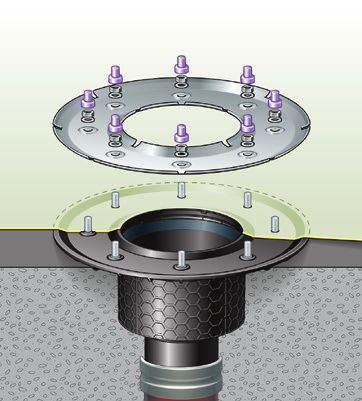
Maßangaben
Abbildung zeigt 48378.11                              Abbildung zeigt 48778.63

                                                                               273

                                                           min. 25
                                                           max. 70
                                                                               132

                                                                                                      H
                                                                                                    147
                                                                                              DN
                                                                                        B

(Art.-Nr. 48358, 48378, 48383, 48311)                  (Art.-Nr. 48758, 48778, 48783, 48711)
   DN        50        70         80           100        DN        50        70         80               100
    B        210     122,8       136,5        136,5        B        210     122,8       136,5            136,5
    H        120      109         92           92          H        120      109         92               92

Abbildung zeigt 48411.11                              Abbildung zeigt 48811.41

                           150                                                        273
                                    min. 20
                                    max. 76

                                                                                      150
                                                                     min. 25
                                                                     max. 67
                                 91

                                                                                                   107
                                 110

                                                                                                   110
                                                                                      ••
                           DN                                                         DN
                         135                                                    135
(Art.-Nr. 48458, 48478, 48483, 48411)                  (Art.-Nr. 48858, 48878, 48883, 48811)
   DN        50        70         80           100       DN          50        70            80          100
    H        100       110        110          110        H          100       110           110         110
Aussparungsmaße: 180 x 180 mm                          Aussparungsmaße: 180 x 180 mm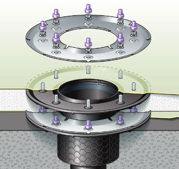
Einbauhinweise
Einbau mit Lippendichtung (im Lieferumfang des Aufsatzstückes) Rohrleitungsanschluss nach DIN 19522 (SML-Rohranschluss):
Bei Bodenaufbauten ohne Abdichtungsbahn, bzw. dort, wo das Ein- DN 50 70 80 100
dringen von rückstauendem Abwasser aus der Rohrleitung in den Bo- DA 58 78 83 110
denaufbau verhindert werden soll, wird zwischen Aufsatzstück und
Grundkörper, bzw. Verlängerungsstück die KESSEL-Lippendichtung Flexibler Niveauausgleich
nach DIN EN 681-1 montiert. Lippendichtung Aufsatzstück neigbar und teleskopisch höhenverstellbar zur
Anpassung an das Bodenniveau sowie drehbar zur Angleichung
an das Fliesenraster (1). Minimale Einbauhöhe durch Absägen
(2). Mit einem KESSEL-Verlängerungsstück kann die Einbautiefe
max. um 120 mm vergrößert werden (3).
Die Dichtung wird in die Nut im Grundkörper gedrückt. Damit wird ein
Herausziehen der Dichtung beim Höhenausgleich des Aufsatzstückes
verhindert.
Einsetzen des Geruchsverschlusses
Geruchsverschluss in den Auslauf des Bodenteils einsetzen und durch
Drehen des Oberteils verriegeln. Die Montage des Brandschutzeinsat-
zes entnehmen Sie der Montageanleitung zum KESSEL-Fire Kit Art. Einbau mit Sickerwasser
Nr. 48100. Ist z.B. in stark belasteten Nassbereichen mit Sickerwasser zu
Verbau des Pressdichtungsflansches (Art.Nr. 48402) rechnen, ist die Lippendichtung zu entfernen. Dadurch kann das
Beim Verpressen der Dichtungsbahnen sind die Drehmomente wie auf anfallende Sickerwasser zwischen Aufsatzstück und Grundkör-
folgender Tabelle aufgeführt zu beachten. per, bzw. Verlängerungsstück sicher in den Ablauf abgeführt
Werkstoff Dichtbahn Anzugsmoment werden.
empfohlen*
Sickerwasserableitung
Bitumenbahn 4-6 Nm
PIB mit Bitumenbahn 4-6 Nm
verklebt
Bitumenbahn mit Träger- 6-8 Nm (* in Anlehnung an DIN
einlage aus Glasgewebe 18195)
Elastomere Sperrbahn 48982 4-6 Nm
Bauzeitschutzabdeckung
Beim Einbau in drückendes Wasser muss die Dichtungsbahn nach Während der Bauzeit kann der KESSEL-Boden-/Deckenablauf
DIN 18195-6 mind. eine Dicke von 1,5 mm bei PIB und 2,0 mm bei Ecoguss mit der mitgelieferten Bauzeitschutzabdeckung gegen
ECB aufweisen. Beim Einbau mit Heißbitumen ist die Temperatur im das Eind ringen von
Pressdichtungsflansch-bereich von max. 400°C kurzfristig (ca. 1-2 Schmutz, z.B. Mörtel,
Min) zulässig. Beton etc. geschützt
Hinweis: Pressdichtungsflansch und Grundkörper sind bis max. 70 werden.
kg belastbar.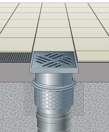
Einbauvorschlag
66 1 2
E coguss Auslauf senkrecht
➀ Bodenbelag
3 ➁ Bodenbelag-Kleber
9 7
4 ➂ Estrich
➃ Trennlage
➄ Betondecke
8
5 ➅ Dehnungsfuge
➆ Aufsatzstück mit Rost
➇ Geruchsverschluss
10
➈ Pressdichtungsflansch
➉ senkrechter Ablauf
66 1
Ecoguss Auslauf seitlich
2
➀ Bodenbelag
➁ Bodenbelag-Kleber
3
➂ Estrich
9 7 ➃ Trennlage
4
➄ Betondecke
➅ Dehnungsfuge
8 ➆ Aufsatzstück mit Rost
5
➇ Geruchsverschluss
10
➈ Pressdichtungsflansch
➉ waagrechter Ablauf
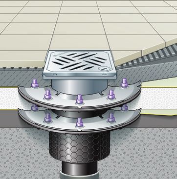
KESSEL-Bodenablauf mit Pressdichtungsflansch Technische Daten:
Grundkörper mit Oberkante Pressdichtungsflansch bündig mit der Betondecke einbauen. Temperaturbeständigkeit nach EN
Bauseits verlegte Dichtungsfolie im Ablaufbereich entsprechend ausschneiden. Die Ab- 1253-1 Klasse A; Ablaufleistung
dichtung muss bis an den Kragen des Ablaufkörpers herangeführt werden. Dichtungsbahn 1,8 l/s bei 20 mm Anstau, 1,1 l/s
gemäß den gültigen Normen und Vorschriften auf den Pressdichtungsflansch aufbringen bei 10 mm Anstau
und mit dem Losflansch verschrauben.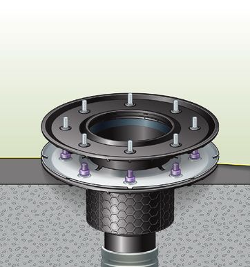
Einbauvorschläge
                                   Ablaufkörper vor dem Gie- Anschluss des Auslauf-                   Aufsatzstück in Grundkörper   Aufbringung des End-
                                   ßen der Decke /Bodenplatte stutzens an HT- bzw. KG-                einstecken und auf Höhe       belages (Fliesenkleber,
Einbau ohne Abdichtung

                                   einsetzen oder nachträg- Rohr vornehmen.                           ausrichten.                   Fliesen).
                                   lich in vorhandene Aus-
                                   sparung einsetzen.

                                   Grundkörper mit aufgesetz- Gegenflansch abnehmen.                  Aufbringung des weiteren   Fliesenverklebung mit
                                   tem Klebeflansch eingießen PVC-Dichtbahn-Ausschnitt (ca. 50        Bodenaufbaus (Estrich).    Fliesenkleber.
                                                                                                      Aufsatzstück auf Grundkör-
                                   oder nachträglich einsetzen. x 50 cm) auf Flansch kleben, ver-
Einbau mit Klebeflansch

                                                                legte Raumdichtung an Ausschnitt      per aufsetzen. Höhenniveau
                                                                                                      und Ausrichtung auf Grund-
                                                                verkleben, Gegenflansch wieder        lage von Endhöhe und
                                                                aufschrauben. Haltering zur Sicker-   Flie-senflucht vornehmen.
                                                                wasserableitung auf Flansch
                                                                setzen.

                                   Einbringen der ersten            Einsetzen von Verlänge-           Aufbringung des weiteren      Erstellung des restlichen
                                   Dichtbahn.                       rungsstück mit Dicht-             Bodenaufbaus, anschließend    Bodenaufbaus.
Einbau mit Pressdichtungsflansch

                                                                    flansch.                          zweite Dichtbahn verlegen.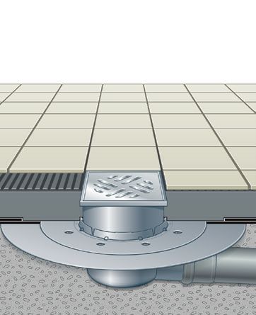
Schallschutz
➀
➁
➂
➃

➄

    ➀ Fliesen ➁ Fliesenkleber ➂ Estrich ➃ Schallschutz ➄ Betondecke
➀
➁
➂
➃

➄

      Ecoguss mit Brandschutzeinsatz
      Fire-Kit

Nach Messung des Fraunhofer Instituts Stuttgart: Boden-/Deckenablauf Ecoguss
- 16 dB(A) nach DIN 4109 - 14 dB(A) nach VDI 4100 SST III
Nach Messung des Fraunhofer Instituts Stuttgart: Boden-/Deckenablauf Ecoguss mit Fire-Kit
- 23 dB(A) nach DIN 4109 - 20 dB(A) nach VDI 4100 SST III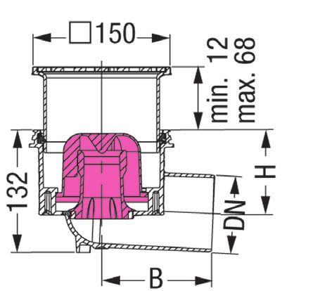
INSTALLATION AND FITTING INSTRUCTIONS

KESSEL floor/roof drain
Ecoguss

                                        With typical KESSEL advantages
                                        • M etallic composite material, metallic
                                          properties and yet still corrosion-free
                                        • N o earthing necessary
                                        • O ptimum pipe cleaning thanks to easy
                                          removal of odour traps
                                        • T elescopic height adjustment
                                          of upper section, can be tilted and turned
                                          to adapt to tile pattern
                                        • F irmly inserted lip seal
                                        • P reventive fire protection
                                          with KESSEL Fire Kit
Illustration shows art. no. 48 878.64   • C an be combined with design covers
                 DIN EN 1253

                                                       Place expansion joint between
                                                       end cover and upper section

                                                       Änderungsstand:		2020/01
                                                       Sachnummer:		325-913
Dimension specifications
Illustration shows 48378.11                             Illustration shows 48778.63

                                                                                  273

                                                              min. 25
                                                              max. 70
                                                                                  132

                                                                                                         H
                                                                                                       147
                                                                                                 DN
                                                                                           B

Art. no. 48358, 48378, 48383, 48311)                     Art. no. 48758, 48778, 48783, 48711)
   DN        50        70         80             100        DN        50        70         80                100
    B       210      122.8       136.5          136.5        B       210      122.8       136.5             136.5
    H       120        109        92             92          H       120        109        92                92

Illustration shows 48411.11                             Illustration shows 48811.41

                              150                                                        273
                                      min. 20
                                      max. 76

                                                                                         150
                                                                        min. 25
                                                                        max. 67
                                    91

                                                                                                      107
                                    110

                                                                                                      110
                                                                                         ••
                              DN                                                         DN
                        135                                                          135
Art. no. 48458, 48478, 48483, 48411)                     Art. no. 48858, 48878, 48883, 48811)
   DN        50        70         80             100       DN           50        70            80          100
    H       100        110        110            110        H           100       110           110         110
Installation area: 180 x 180 mm                          Installation area: 180 x 180 mm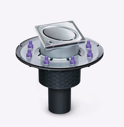
Installation instructions
Installation with lip seal (included in the scope of delivery of the Pipeline connection in accordance with DIN 19522 (SML pipe
upper section)                                                          connection):
In the case of floor constructions without sealing sheet, or wherever DN           50          70          80         100
the penetration of wastewater flowing back from the pipe into the floor DA         58          78          83         110
construction is to be avoided, the KESSEL lip seal must be mounted Flexible level adjustment
between the upper section and the drain body or extension section, in The upper section can be tilted and has telescopic height ad-
accordance with DIN EN 681-1.                                           justment for adaptation to the floor level, and it can be turned
                                   Lip seal                             to match the tile pattern (1). Minimum installation height thanks
                                                                        to sawing to size (2). The installation depth can be enlarged by
                                                                        a maximum of 120 mm using a KESSEL extension section (3).

The sealing gasket is pressed into the groove in the drain body. This
prevents that the sealing gasket is pulled out when the upper section
is adapted to the required height.

Inserting the odour trap
Insert the odour trap into the outlet of the base section and seal it by
turning the upper part. See the mounting instructions for the KES- Installation with seepage water
SEL Fire-Kit art. no. 48100 for instructions on how to install the fire If seepage water is to be expected in extremely wet areas, for
protection kit.                                                          example, the lip seal must be removed. This allows the seepage
                                                                         water to be discharged safely between the upper section and
Fitting the pressure sealing flange Art. no. 48402)
                                                                         drain body or extension section into the outlet.
When pressing the sealing sheets, the torques listed in the table below
must be heeded.
                                                                                                                 Seepage water
  Sealing sheet material        Tightening torque
                                recommended*                                                                     discharge
  Bitumen sheet                         4-6 Nm
  PIB glued with bitumen sheet          4-6 Nm

  Bitumen sheet with backing            6-8 Nm   (* following DIN 18195)
  made of glass fabric                                                     Temporary protective cover
  Elastomer waterproofing sheet 48982   4-6 Nm
                                                                           During construction work, the KESSEL floor/roof drain Ecoguss
For installation in water load, the sealing sheet must have a              can be protected against the penetration of dirt .e.g. mortar,
thickness of at least 1.5 mm for PIB and 2.0 mm for ECB in accordance      concrete etc. using the
with DIN EN 18195-6. When hot bitumen is used, the temperature in          temporary protective
the area around the pressure sealing flange may reach max. 400°C           cover provided.
briefly (approx. 1-2 min).
Note: Max. load on pressure sealing flange and drain body is 70 kg.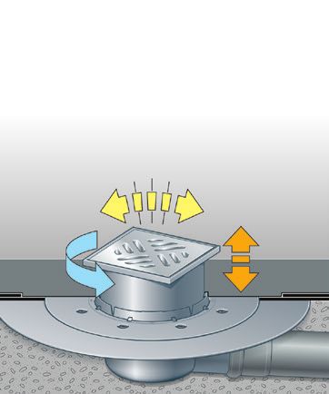
Installation suggestion
                               66                       1             2
                                                                                         Ecoguss - vertical outlet
                                                                                         ➀ Floor covering
               3                                                                         ➁ Adhesive
                           9             7
                                                                          4              ➂ Cement screed
                                                                                         ➃ Membrane
                                                                                         ➄ Concrete ceiling
                                         8
                                                                          5              ➅ Expansion joint
                                                                                         ➆	Upper section and cover
                                                                                         ➇ Odour trap
                                         10
                                                                                         ➈ Pressure sealing flange
                                                                                         ➉ Vertical outlet

                               66                        1
                                                                                       E coguss - horizontal outlet
                                                                 2
                                                                                        ➀ Floor covering
                                                                                        ➁ Adhesive
                   3
                                                                                        ➂ Cement screed
                           9             7                                              ➃ Membrane
                                                                  4
                                                                                        ➄ Concrete ceiling
                                                                                        ➅ Expansion joint
                                         8                                             ➆	Upper section and cover
                       5
                                                                                        ➇ Odour trap
                                                                 10
                                                                                       ➈ Pressure sealing flange
                                                                                       ➉ Horizontal outlet
KESSEL floor drain with pressure sealing flange                                             Technical data
Install the drain body with the upper edge of the pressure sealing flange flush to the con- Temperature resistance as per EN
crete surface. Cut out the sealing sheeting already laid in the drain area as required. The 1253-1 Class A; Draining capacity
waterproofing layer must be up to the collar of the drain body. Apply the seal sheeting to 1.8 l/s with 20 mm accumulation,
the pressure sealing flange according to the valid standards and regulations and screw 1.1 l/s with 10 mm accumulation.
to the loose flange.
Installation suggestions
Installation without waterproofing layer
Insert the drain body before Connect the drain muff to Insert the upper section into Apply the final flooring (tile
the roof/floor is cast in con- the HT or KG pipe. the drain body and align to adhesive, tiles).
crete or retrofit afterwards the right height.
in existing recess.
Cast in the drain body with Remove the counterflange. Glue Apply the next layer of floor Glue tiles in place with
glue flange in place or fit the PVC sealing sheet cut-out structure (screed). Insert tile adhesive.
Installation with glued flange
(approx. 50 x 50 cm) to the flange, upper section onto drain
later. body. Undertake height
glue the room seal to the cut-out,
levelling and alignment on
screw the counterflange back the basis of final height and
on again. Set supporting ring for tile alignment.
discharging seepage water onto
flange.
Position the first sealing Insert the extension section Apply the further floor struc- Finish the remaining
Installation with pressure sealing flange
sheet. with sealing flange. ture, then lay the second floor structure.
sealing sheet.Sound protection
➀
➁
➂
➃
➄
➀ Tiles ➁ Tile adhesive ➂ Screed ➃ Sound protection ➄ Concrete ceiling
➀
➁
➂
➃
➄
Ecoguss with fire protection insert
Fire-Kit
Measurements carried out by the Fraunhofer Institute in Stuttgart: Floor/roof drain Ecoguss
- 16 dB(A) according to DIN 4109 - 14 dB(A) according to VDI 4100 SST III
Measurements carried out by the Fraunhofer Institute in Stuttgart: Floor/roof drain Ecoguss with Fire-Kit
- 23 dB(A) according to DIN 4109 - 20 dB(A) according to VDI 4100 SST IIIINSTRUCTIONS DE POSE ET DE MONTAGE
Siphon de sol / siphon de plancher
KESSEL Ecoguss
Avantages spéciaux KESSEL
• M atériau composite métallique
propriétés métalliques sans risque de corrosion
• M ise à la terre superflue
• C urage optimal des tuyaux grâce aux
dispositifs anti-odeur faciles à enlever
• R ehause à réglable en hauteur télescopique,
inclinable et pivotante
par rapport au couvercle à carreler individuel
• J oint à lèvre engagé à demeure
• P rotection coupe-feu préventive
grâce au KESSEL-Fire-Kit
Le dessin représente la Réf. n° 48 878.64 • C ombinable avec des grilles design
DIN EN 1253
Placer le joint de dilatation entre le
revêtement final et la rehausse.
Änderungsstand: 2020/01
Sachnummer: 325-913Cotes
Le dessin représente 48378.11 Le dessin représente 48778.63
273
min. 25
max. 70
132
H
147
DN
B
(Réf. n° 48358, 48378, 48383, 48311) (Réf. n° 48758, 48778, 48783, 48711)
DN : 50 70 80 100 DN : 50 70 80 100
B 210 122,8 136,5 136,5 B 210 122,8 136,5 136,5
H 120 109 92 92 H 120 109 92 92
Le dessin représente 48411.11 Le dessin représente 48811.41
150 273
min. 20
max. 76
150
min. 25
max. 67
91
107
110
110
••
DN DN
135 135
(Réf. n° 48458, 48478, 48483, 48411) (Réf. n° 48858, 48878, 48883, 48811)
DN : 50 70 80 100 DN : 50 70 80 100
H 100 110 110 110 H 100 110 110 110
Réservation : 180 x 180 mm Réservation : 180 x 180 mmInstructions de pose
Pose avec un joint à lèvre (compris dans le détail de livraison de Raccordement des tuyaux selon DIN 19522 (connexion SML) :
la rehausse) DN 50 70 80 100
Dans le cas de constructions au sol sans bande d’étanchéité, resp. DA 58 78 83 110
s’il est requis d’éviter la pénétration des eaux usées refoulées par la
canalisation dans la structure du sol, il convient de monter le joint à Compensation de niveau flexible
lèvre KESSEL selon DIN EN 681-1 entre la rehausse et le corps de Rehausse inclinable et à réglage en hauteur télescopique d‘ad-
base ou la pièce de rallonge. aptation au niveau du sol et pivotante par rapport au couvercle
Joint à lèvre à carreler individuel (1). Hauteur de pose minimale par sciage
(2). Possibilité d’augmenter la profondeur de pose de 120 mm
maximum avec une pièce de rallonge KESSEL (3).
Presser le joint dans la gorge du corps de base. Ainsi, la compensation
de hauteur via la rehausse ne risque pas d’extraire le joint.
Insertion du dispositif anti-odeur
Insérer le dispositif anti-odeur dans la sortie du segment inférieur
et verrouiller en tournant le segment supérieur. Veuillez consulter
les instructions de montage spécifiques à l’insert coupe-feu, Réf. n° Pose en cas d’eau d‘infiltration
48100. Retirer le joint à lèvre si la zone humide est p. ex. fortement
Montage de la bride de compression (Réf. n° 48402) sujette à des infiltrations d’eau. Il s‘agit d’une précaution afin
Observer les couples mentionnés sur le tableau ci-après pour la com- que l’eau d‘infiltration se produisant puisse être bien évacuée
pression des bandes d‘étanchéité. entre la rehausse et le corps de base ou la pièce de rallonge
Matière de la bande d‘étanchéité Couple de serrage dans le siphon.
conseillé*
Évacuation des eaux
Bande bitumeuse 4-6 Nm
PIB collé sur bande bitumeuse 4-6 Nm
d‘infiltration
Bande bitumeuse avec couche support 6-8 Nm (* en s‘appuyant sur la
en tissu de verre textile norme DIN 18195)
Membrane d‘étanchéité en élastomère 48982 4-6 Nm
Couvercle de protection de chantier
En cas de pose dans des eaux poussantes, la bande d‘étanchéité selon Le couvercle de protection de chantier fourni est destiné à pro-
DIN 18195-6 doit présenter une épaisseur d’au moins 1,5 mm si com- téger le siphon de sol / siphon de plancher KESSEL Ecoguss
posée de PIB et de 2,0 mm si composée d’ECB. En cas de pose avec contre la pénétration
du bitume chaud, une température maximale de 400 °C est temporai- des saletés, p. ex. le
rement admissible (pendant env. 1 à 2 minutes) dans la zone de la mortier, béton, etc. au
bride de compression. cours de la phase de
Observation : la bride de compression et le corps de base support- construction.
ent une mise en charge de 70 kg maximum.Suggestion de pose
66 1 2
Ecoguss - Sortie verticale
➀ Revêtement de sol
3 ➁ Colle pour carrelage
9 7
4 ➂ Chape
➃ Emplacement de séparation
➄ Dalle en béton
8
5 ➅ Joint de dilatation
➆ Rehausse avec grille
➇ Dispositif anti-odeur
10
➈ Bride de compression
➉ Sortie verticale
66 1
E coguss - Sortie latérale
2
➀ Revêtement de sol
➁ Colle pour carrelage
3 ➂ Chape
9 7 ➃ Emplacement de séparation
4
➄ Dalle en béton
➅ Joint de dilatation
8 ➆ Rehausse avec grille
5
➇ Dispositif anti-odeur
10
➈ Bride de compression
➉ Sortie verticale
Siphon de sol KESSEL avec bride de compression Caractéristiques techniques
Poser le corps de base avec le bord supérieur de la bride de compression à franc-bord Thermostable suivant EN 1253-1,
avec la dalle en béton. Couper la feuille d’étanchéité à prévoir sur site à dimension dans Classe A
la zone du siphon. Abouter la feuille d’étanchéité jusqu’au bord du corps d‘avaloir. Ap- Débit de 1,8 l/s pour un reflux de
pliquer la bande d‘étanchéité sur la bride de compression dans le respect des normes et 20 mm, 1,1 l/s pour un reflux de
prescriptions et la visser avec la bride de décompression. 10 mmSuggestions de pose
Insérer le corps d‘avaloir Raccorder le manchon Introduire la rehausse dans Application du revêtement
avant de couler le plafond d‘écoulement au tuyau HT le corps de base et l’aligner final (colle pour carrelages,
/ la dalle de fondation ou ou de moulage en fonte à la hauteur correcte. carrelage).
Pose sans étanchéité
l’insérer ultérieurement pour canalisation.
dans l’évidement prévu à
cet effet.
Couler le corps de base Retirer la contre-bride. Coller la Application des autres Coller le carrelage avec une
avec la bride à coller mise découpe de bande d‘étanchéité structures du sol (chape). colle pour carrelage.
Pose avec une bride à coller
Placer la rehausse sur le
en place ou insérer la bride en PVC (env. 50 x 50 cm) sur la corps de base. Procéder
ultérieurement. bride, abouter le joint posé au sol
à une compensation de la
à la découpe par collage, revisser hauteur et à l’alignement
la contre-bride. Placer la bague sur la base de la hauteur
d‘arrêt sur la bride pour assurer finale et du carrelage.
l’évacuation des eaux d‘infiltra-
tion.
Application de la première Insertion de la pièce de Application des autres Réalisation de la
Pose avec une bride de compression
bande d‘étanchéité. rallonge avec la bride structures du sol, suivie de la structure résiduelle du sol.
d‘étanchéité. pose de la seconde bande
d‘étanchéité.Insonorisation
➀
➁
➂
➃
➄
➀ Carrelage ➁ Colle pour carrelage ➂ Chape ➃ Insonorisation ➄ Dalle en béton
➀
➁
➂
➃
➄
Ecoguss avec insert coupe-feu
Fire-Kit
Suivant la mesure effectuée par l’institut Fraunhofer de Stuttgart : Siphon de sol / siphon de
plancher Ecoguss
- 16 dB(A) selon DIN 4109 - 14 dB(A) selon VDI 4100 SST III
Suivant la mesure effectuée par l’institut Fraunhofer de Stuttgart : Siphon de sol / siphon de
plancher Ecoguss avec Fire-Kit
- 23 dB(A) selon DIN 4109 - 20 dB(A) selon VDI 4100 SST IIIISTRUZIONI PER L‘INSTALLAZIONE ED IL MONTAGGIO
Scarico di pavimenti e soffitti
KESSEL Ecoguss
Con i tipici vantaggi KESSEL
• M ateriale composito metallico,
con caratteristiche metalliche eppure immune dalla cor-
rosione
• N essuna messa a terra necessaria
• P ulizia dei tubi ottimale tramite le
chiusure antiodore semplici da rimuovere
• R egolabile in altezza telescopicamente
Rialzo inclinabile e girevole
per l’adeguamento al reticolo delle piastrelle
• G uarnizione a labbra posata fissa
• P rotezione antincendio preventiva
La figura mostra il cod.art. 48 878.64 con Fire-Kit KESSEL
• C ombinabile con le griglie Design
DIN EN 1253
Posare il giunto di dilatazione tra il rivesti-
mento finale ed
il rialzo.
Änderungsstand: 2020/01
Sachnummer: 325-913Misure
La figura mostra il modello 48378.11 La figura mostra il modello 48778.63
273
min. 25
max. 70
132
H
147
DN
B
(Cod.art. 48358, 48378, 48383, 48311) (Cod.art. 48758, 48778, 48783, 48711)
DN 50 70 80 100 DN 50 70 80 100
B 210 122,8 136,5 136,5 B 210 122,8 136,5 136,5
H 120 109 92 92 H 120 109 92 92
La figura mostra il modello 48411.11 La figura mostra il modello 48811.41
150 273
min. 20
max. 76
150
min. 25
max. 67
91
107
110
110
••
DN DN
135 135
(Cod.art. 48458, 48478, 48483, 48411) (Cod.art. 48858, 48878, 48883, 48811)
DN 50 70 80 100 DN 50 70 80 100
H 100 110 110 110 H 100 110 110 110
Misura apertura grezza: 180 x 180 mm Misura apertura grezza: 180 x 180 mmIndicazioni per l’installazione
Installazione con guarnizione a labbra (in dotazione con il rialzo) Collegamento dei tubi a norma DIN 19522 (collegamento dei
In presenza di strutture di pavimenti senza impermeabilizzazione ov- tubi SML):
vero nei casi in cui deve essere evitata la penetrazione nella pavimen- DN 50 70 80 100
tazione delle acque di scarico rifluenti dalle tubazioni, tra il rialzo e il DA 58 78 83 110
corpo base ovvero il pezzo intermedio viene montata la guarnizione a Compensazione del livello flessibile
labbra KESSEL a norma DIN EN 681-1. Rialzo inclinabile e regolabile in altezza telescopicamente per
Guarnizione a labbra l‘adattamento al livello del pavimento e girevole per l’adegua-
mento al reticolo delle piastrelle (1). Altezza di installazione mi-
nima grazie alla possibilità di taglio (2). Con il pezzo di prolunga
KESSEL è possibile aumentare la profondità di installazione di
La guarnizione viene spinta nella scanalatura nel corpo base. In 120 mm al massimo (3).
questo modo viene impedita l’estrazione della guarnizione durante la
regolazione in altezza del rialzo.
Applicazione della chiusura antiodore
Inserire la chiusura antiodore nello scarico della base e bloccarla
ruotando la parte superiore. Il montaggio del kit di protezione antin-
cendio opzionale è ricavabile dalle istruzioni di montaggio del Fire-Kit Installazione con l’acqua di infiltrazione
KESSEL, cod.art. 48100. Se si prevede la presenza di acqua di infiltrazione, ad esempio
Montaggio della flangia a guarnizione a pressione (Cod.art. 48402) nelle aree umide molto sollecitate, la guarnizione a labbra deve
Nella compressione delle guaine impermeabilizzanti devono essere te- essere rimossa. In questo modo, l’acqua di infiltrazione prodot-
nuti in considerazione i momenti torcenti riportati nella tabella seguente. tasi può essere incanalata in sicurezza nello scarico tra il rialzo
Materiale della guaina Momento di serraggio
e il corpo base ovvero il pezzo intermedio.
impermeabilizzante raccomandato* Canalizzazione dell‘ac-
Guaina di bitume 4-6 Nm qua infiltrata
PIB incollato alla 4-6 Nm (*in base alla norma DIN
guaina di bitume 18195)
Guaina di bitume con rinforzo 6-8 Nm
portante di tessuto di vetro
Guaina impermeabilizzante in elastomero 48982 4-6 Nm
Copertura protettiva da cantiere
In caso di installazione in presenza di pressione idrica, a norma Durante i lavori edili, lo scarico di pavimenti e soffitti KESSEL
DIN 18195-6, il materiale impermeabilizzante deve presentare uno Ecoguss può essere protetto con la copertura protettiva da
spessore minimo di 1,5 mm per il PIB e di 2,0 mm per l’ECB. In caso cantiere in dotazione
di installazione nel bitume caldo, la temperatura nell‘area della flangia a contro la penetrazione
guarnizione a pressione può raggiungere i 400 °C al massimo per breve della sporcizia, come
tempo (circa 1-2 minuti). ad esempio la malta, il
Avvertenza: la flangia a guarnizione a pressione e il corpo base hanno calcestruzzo, ecc.
una portata massima di 70 kg.Suggerimento di installazione
66 1 2
ECOGUSS uscita verticale
➀ Pavimentazione
3 ➁ Adesivo per piastrelle
9 7
4 ➂ Massetto
➃ Strato di separazione
➄ Copertura in calcestruzzo
8
5 ➅ Giunto di dilatazione
➆ Rialzo con griglia
➇ Chiusura antiodore
10
➈ Flangia a guarnizione a pressione
➉ Uscita verticale
66 1
ECOGUSS uscita laterale
2
➀ Pavimentazione
➁ Adesivo per piastrelle
3
➂ Massetto
9 7 ➃ Strato di separazione
4
➄ Copertura in calcestruzzo
➅ Giunto di dilatazione
8 ➆ Rialzo con griglia
5
➇ Chiusura antiodore
10
➈ Flangia a guarnizione a pressione
➉ Uscita laterale
Scarico a pavimento KESSEL con flangia a guarnizione a pressione Dati tecnici
Installare il corpo base con il bordo superiore della flangia fissa a livello della soletta di Resistenza alla temperatura a
calcestruzzo. Tagliare adeguatamente la pellicola impermeabilizzante posata localmente norma EN 1253-1, classe A
nell‘area dello scarico. L’impermeabilizzazione deve essere condotta fino al collare del Prestazione di scarico di 1,8 l/s
corpo di scarico. Applicare il materiale impermeabilizzante sulla flangia fissa ai sensi con 20 mm di ristagno, di 1,1 l/s
delle norme e delle prescrizioni vigenti e avvitare con la flangia libera. con 10 mm di ristagnoSuggerimenti di installazione
Posare il corpo di scarico Eseguire il collegamento Innestare il rialzo nel corpo Applicazione del rivesti-
Installaz. senza impermeabilizzazione
prima della colata del sof- del bocchettone di scarico base e portare all’altezza mento finale (adesivo per
fitto/pavimento o succes- al tubo ad alta temperatura corretta. piastrelle, piastrelle).
sivamente nell’apertura ovvero al tubo standard per
grezza disponibile. canali.
Posare il corpo base con la Rimuovere la contro-flangia. Incollare Applicazione dell’ulteriore Incollaggio delle piastrelle
flangia adesiva applicata o un ritaglio di guaina impermeabiliz- pavimentazione (mas- con
Installaz. con flangia adesiva
zante di PVC (circa 50 x 50 cm) sulla setto). Collocare il rialzo adesivo per piastrelle
inserirlo successivamente. flangia, incollare l’impermeabilizzazi- sul corpo base. Eseguire
one del locale al ritaglio, avvitare nuo- il livellamento in altezza
vamente la contro-flangia. Applicare e l’orientamento in base
alla flangia l‘anello di fissaggio per all‘altezza finale e alla posa
la canalizzazione dell‘acqua infiltrata. delle piastrelle.
Installaz. con flangia a guarnizione a pressione
Posa della prima guaina Installazione del pezzo in- Applicazione della pavi- Realizzazione della
impermeabilizzante. termedio con giunto piano. mentazione ulteriore, seguita pavimentazione rimanente.
dalla posa della seconda
guaina impermeabilizzante.Insonorizzazione
➀
➁
➂
➃
➄
➀ Piastrelle ➁ Adesivo per piastrelle ➂ Massetto ➃ Insonorizzazione ➄ Soletta in calcestruzzo
➀
➁
➂
➃
➄
Ecoguss con kit di protezione antincen-
dio opzionale Fire-Kit
Secondo la misurazione dell›istituto Fraunhofer di Stoccarda: Scarico di pavimenti e soffitti Ecoguss
- 16 dB(A) a norma DIN 4109 - 14 dB(A) a norma VDI 4100 SST III
Secondo la misurazione dell›istituto Fraunhofer di Stoccarda: Scarico di pavimenti e soffitti Ecoguss con Fire-Kit
- 23 dB(A) a norma DIN 4109 - 20 dB(A) a norma VDI 4100 SST IIIINBOUW- EN MONTAGEHANDLEIDING
KESSEL vloer-/dakafvoer
Ecoguss
Met voor KESSEL typische voordelen
• m etaalachtig compoundmateriaal metaalachtige
eigenschappen en toch corrosievrij
• g een aarding nodig
• o ptimale reiniging van de buis door eenvoudig
uitneembare stanksloten
• telescopisch in hoogte verstelbaar
opzetstuk, kantelbaar en draaibaar
voor aanpassing aan het tegelraster
• v ast ingelegde lipafdichting
• p reventieve brandwerendheid
met KESSEL-Fire Kit
Afb. laat zien art.nr. 48 878.64 • m et designroosters combineerbaar
DIN EN 1253
Dilatatievoeg tussen eindafdekking en
opzetstuk leggen.
Änderungsstand: 2020/01
Sachnummer: 325-913Maatgegevens
Afbeelding laat zien 48378.11 Afbeelding laat zien 48778.63
273
min. 25
max. 70
132
H
147
DN
B
(Art.nr. 48358, 48378, 48383, 48311) (Art.nr. 48758, 48778, 48783, 48711)
DN 50 70 80 100 DN 50 70 80 100
B 210 122,8 136,5 136,5 B 210 122,8 136,5 136,5
H 120 109 92 92 H 120 109 92 92
Afbeelding laat zien 48411.11 Afbeelding laat zien 48811.41
150 273
min. 20
max. 76
150
min. 25
max. 67
91
107
110
110
••
DN DN
135 135
(Art.nr. 48458, 48478, 48483, 48411) (Art.nr. 48858, 48878, 48883, 48811)
DN 50 70 80 100 DN 50 70 80 100
H 100 110 110 110 H 100 110 110 110
Uitsparingsmaten: 180 x 180 mm Uitsparingsmaten: 180 x 180 mmInbouwinstructies
Inbouw met lipafdichting (wordt meegeleverd met het opzetstuk) Buisleidingaansluiting volgens DIN 19522 (SML buisaanslui-
Bij vloerconstructies zonder afdichtingsbaan, c.q. op plaatsen waar ting):
het binnendringen van terugstuwend water vanuit de buisleiding naar DN 50 70 80 100
de vloerconstructie moet worden voorkomen, wordt tussen het op- DA 58 78 83 110
zetstuk en het basiselement, c.q. tussenstuk de KESSEL lipafdichting Flexibele niveaucompensatie
volgens DIN EN 681-1 gemonteerd. Opzetstuk kantelbaar en telescopisch in hoogte verstelbaar voor
Lipafdichting aanpassing aan het vloerniveau alsmede draaibaar voor aan-
passing aan heet tegelraster (1). Minimale inbouwhoogte door
afzagen (2). Met een KESSEL verlengstuk kan de inbouwdiepte
max. met 120 mm worden vergroot (3).
Het afsluitrubber wordt in de groef in het basiselement gedrukt. Hier-
door wordt voorkomen dat het afsluitrubber bij de compensatie van
de hoogte van het opzetstuk eruit wordt getrokken.
Plaatsen van het stankslot
Stankslot in de afvoer van het bodemgedeelte plaatsen en vergren-
delen door draaiing van het bovengedeelte. De montage van het
brandpreventie-inzetstuk staat vermeld in de montagehandleiding Inbouw met kwelwater
van de KESSEL-Fire Kit art.nr. 48100. Als bv. in sterk belaste natte ruimten rekening moet worden
Installatie van de persafdichtingsflens (Art.nr. 48402) gehouden met kwelwater, moet de lipafdichting worden verwij-
Bij het persen van afdichtbanen moet worden gelet op de op de derd. Daardoor kan het optredende kwelwater tussen opzetstuk
volgende tabel vermelde draaimomenten. en basiselement, c.q. tussenstuk veilig worden afgevoerd naar
Materiaal afdichtbaan Aanhaalmoment de afvoer.
aanbevolen*
Kwelwaterafvoer
Bitumenbaan 4-6 Nm
PIB met bitumenbaan 4-6 Nm
vastgelijmd
PIB met draag- 6-8 Nm (* in navolging van DIN
tussenlaag van glasweefsel 18195)
Elastomeer afsluitbaan 48982 4-6 Nm
Beschermingsdeksel t.b.v. de bouwfase
Bij de inbouw in drukkend water moet de afdichtbaan volgens Tijdens de bouwtijd kan de KESSEL vloer-/dakafvoer Ecoguss
DIN 18195-6 minimaal een dikte van 1,5 mm bij PIB en 2,0 mm bij met het meegeleverde beschermingsdeksel t.b.v. de bouwfase
ECB bezitten. Bij de inbouw met hete bitumen is een temperatuur in tegen het binnendrin-
de zone van de persafdichtingsflens van max. 400 °C kortstondig (ca. gen van vuil, bv. mor-
1-2 min.) toegestaan. tel, beton, etc. worden
Aanwijzing: Persafdichtingsflens en basiselement zijn met max. 70 beschermd.
kg belastbaar.Inbouwsuggestie
66 1 2
Ecoguss uitloop vertical
➀ Bodembedekking
3 ➁ Tegellijm
9 7
4 ➂ Afwerkvloer
➃ Scheidingslaag
➄ Betonnen plafond
8
5 ➅ Uitzelvoeg
➆ Opzetstuk mit rooster
➇ Stankslot
10
➈ Persafdichtingsflens
➉ Onder-uitloop
66 1
Ecoguss uitloop horizontaal
2
➀ Bodembedekking
➁ Tegellijm
3
➂ Afwerkvloer
9 7 ➃ Scheidingslaag
4
➄ Betonnen plafond
➅ Uitzelvoeg
8 ➆ Opzetstuk mit rooster
5
➇ Stankslot
10
➈ Persafdichtingsflens
➉ Uitloop horizontal
KESSEL vloerafvoer met persafdichtingsflens Technische gegevens
Basiselement met bovenrand persafdichtungsflens flens gelijk met betondek inbouwen. Op locatie Temperatuurbestendigheid
geïnstalleerde afdichtingsfolie in afvoerzone navenant uitsnijden. De afdichting moet tot tegen volgens EN 1253-1 klasse A
de kraag van het afvoerelement worden gevoerd. Afdichtingsbaan volgens de geldige normen Afvoervermogen 1,8 l/s bij 20
en voorschriften op de ersafdichtungsflens aanbrengen en vastschroeven op de losse flens. mm opstuwing, 1,1 l/s bij 10 mm
opstuwingInbouwsuggesties
Afvoerelement plaatsen Aansluiting van de uitlo- Opzetstuk in basiselement Aanbrengen van de eindaf-
voordat het plafond/de op-ansluiting op HT- c.q. steken en uitlijnen op dekking (tegellijm, tegels).
Inbouw zonder afdichting
vloerplaat wordt gegoten KG-buis uitvoeren. hoogte.
of achteraf in aanwezige
uitsparing plaatsen.
Basiselement met opgezette Contraflens wegnemen. Uitsnijdsel Aanbrengen van de rest Tegelverlijming met
lijmflens ingieten of achteraf van pvc afdichtbaan (ca. 50 x 50 van de vloerconstructie tegellijm.
cm) op flens lijmen, geïnstalle- (afwerkvloer). Opzetstuk
plaatsen. op basiselement plaatsen.
Inbouw met lijmflens
erd afsluitrubber van ruimte aan
Hoogteniveau en uitlijning
uitsnijdsel vastlijmen, contraflens op basis van eindhoogte en
weer opschroeven. Draagring voor tegelrij aanbrengen.
afvoer van kwelwater op flens
zetten.
Inbrengen van de eerste Plaatsen van verlengstuck Aanbrengen van de rest van Realisatie van de rest van de
afdichtbaan. met afdichtflens. de vloerconstructie, vervolgens vloerconstructie.
Inbouw met persafdichtingsflens
tweede afdichtbaan aanleggen.Geluiddichtheid
➀
➁
➂
➃
➄
➀ Tegels ➁ Tegellijm ➂ Afwerkvloer ➃ Geluiddichtheid ➄ Betondek
➀
➁
➂
➃
➄
Ecoguss met brandpreventieset
Fire-Kit
Volgens meting van het Fraunhofer Institut Stuttgart: vloer-/dakafvoer Ecoguss
- 16 dB(A) conform DIN 4109 - 14 dB(A) conform VDI 4100 SST III
Volgens meting van het Fraunhofer Institut Stuttgart: vloer-/dakafvoer Ecoguss met Fire-Kit
- 23 dB(A) conform DIN 4109 - 20 dB(A) conform VDI 4100 SST IIIINSTRUKCJA ZABUDOWY I MONTAŻU
Wpust podłogowy/stropowy KESSEL
Ecoguss
Z typowymi dla produktów firmy KESSEL za-
letami:
• M etaliczne tworzywo kompozytowe,
cechy metalu, a jednocześnie brak korozji
• N iepotrzebne uziemienie
• O ptymalne czyszczenie rury dzięki
łatwo wyjmowanym syfonom
• N asada z teleskopową regulacją wysokości,
nachylana i obrotowa,
z możliwością dopasowania do wzoru płytek
• Ł atwa w montażu uszczelka wargowa
• P rewencyjna ochrona przeciwpożarowa
Na rysunku przedstawione są art.nr 48 878.64 z zestawem FireKit KESSEL
• M ożliwość łączenia z kratkami o ciekawym de-
DIN EN 1253 signie
Między warstwą końcową i
nasadą należy wykonać szczelinę
dylatacyjną.
Änderungsstand: 2020/01
Sachnummer: 325-913Wymiary
Na rysunku: 48378.11 Na rysunku: 48778.63
273
min. 25
max. 70
132
H
147
DN
B
(nr art. 48358, 48378, 48383, 48311) (nr art. 48758, 48778, 48783, 48711)
DN 50 70 80 100 DN 50 70 80 100
B 210 122,8 136,5 136,5 B 210 122,8 136,5 136,5
H 120 109 92 92 H 120 109 92 92
Na rysunku: 48411.11 Na rysunku: 48811.41
150 273
min. 20
max. 76
150
min. 25
max. 67
91
107
110
110
••
DN DN
135 135
(nr art. 48458, 48478, 48483, 48411) (nr art. 48858, 48878, 48883, 48811)
DN 50 70 80 100 DN 50 70 80 100
H 100 110 110 110 H 100 110 110 110
Wymiary otworu: 180 x 180 mm Wymiary otworu: 180 x 180 mmWskazówki dotyczące zabudowy
Zabudowa z uszczelką wargową (w zakresie dostawy nasady) Przyłącze rur wg normy DIN 19522 (przyłącze rur SML):
W przypadku powierzchni podłogi bez taśmy uszczelnia- DN 50 70 80 100
jącej lub tam, gdzie wymagana jest ochrona przed ściekami DA 58 78 83 110
piętrzącymi się z rury do powierzchni podłogi, należy między
nasadą i korpusem wpustu lub łącznikiem zastosować uszc- Elastyczne wyrównanie poziomu
zelkę wargową KESSEL zgodnie z normą DIN EN 681-1. Nasada jest nachylana, posiada teleskopową regulację
Uszczelka wargowa wysokości w celu dopasowania do poziomu podłogi
oraz jest obrotowa, co umożliwia dopasowanie do wzoru
płytek (1). Minimalna wysokość zabudowy dzięki możli-
wości odpiłowania (2). Element przedłużający KESSEL
Uszczelkę należy wcisnąć w rowek w korpusie wpustu. Zapo- umożliwia zwiększenie głębokości zabudowy o maks.
biega to jej wypadnięciu podczas wyrównywania wysokości 120 mm (3).
nasady.
Włożenie syfonu
Włożyć syfon do odpływu części podłogowej i zablokować
przed obrócenie górnej części. Odnośnie montażu wkładu
przeciwpożarowego patrz instrukcja montażu zestawu FireKit
KESSEL nr art. 48100.
Zabudowa w warunkach z wodą przesiąkającą
Zabudowa dociskowego kołnierza uszczelniającego (nr art.
W bardzo mokrych obszarach, w których może występo-
48402)
wać woda przesiąkająca, należy usunąć uszczelkę war-
Podczas ściskania taśm uszczelniających należy przestrzegać
gową. Dzięki temu woda przesiąkająca między nasadą
momentów obrotowych podanych w poniższej tabeli.
a korpusem wpustu lub łącznikiem może być pewnie
Tworzywo taśmy uszczelniającej Zalecany
moment dociągający* odprowadzana do odpływu.
(* w oparciu o normę
Taśma bitumiczna
Folia PIB klejona z
4-6 Nm
4-6 Nm DIN 18195) Odprowadzenie
taśmą bitumiczną wody przesiąka-
Taśma bitumiczna z wkładką nośną
z tkaniny z włókna szklanego
6-8 Nm jącej
Elastomerowa taśma uszczelniająca 48982 4-6 Nm
Podczas zabudowy w warunkach z wodą na-
pierającą taśma uszczelniająca musi zgodnie z Pokrywa ochronna na czas fazy budowlanej
normą DIN 18195-6 mieć minimalną grubość 1,5 mm (folia Podczas fazy budowlanej wpust podłogowy/stro-
PIB) lub 2,0 mm (folia ECB). Przy zastosowaniu bitumu powy KESSEL Ecoguss można zabezpieczyć dost-
gorącego dopuszczalna jest krótkotrwała temperatura obszaru arczoną pokrywą
dociskowego kołnierza uszczelniającego wynosząca maks. ochronną przed
400°C (przez ok. 1-2 min). brudem, np.
Wskazówka: Maksymalne obciążenie dociskowego kołnierza zaprawą, betonem
uszczelniającego i korpusu wpustu wynosi 70 kg. itp.Propozycja zabudowy
66 1 2
Practicus z pionowym odpływem
➀ Warstwa wykończeniowa
3 ➁ Klej
9 7
4 ➂ Jastrych
➃ Membrana hydroizolacyjna
➄ Strop betonowy
8
5 ➅ Szczelina elastyczna
➆ Nasada z rusztem
➇ Syfon
10
➈ Dociskowy kołnierz uszczeln.
➉ Wpust z odpływem pionowym
66 1
Practicus z bocznym odpływem
2
➀ Warstwa wykończeniowa
➁ Klej
3
➂ Jastrych
9 7 ➃ Membrana hydroizolacyjna
4
➄ Strop betonowy
➅ Szczelina elastyczna
8 ➆ Nasada z rusztem
5
➇ Syfon
10
➈ Dociskowy kołnierz uszczeln.
➉ Wpust z odpływem boczny
Wpust podłogowy KESSEL z dociskowym kołnierzem uszczelniającym Dane techniczne
Zabudować korpus wpustu z górną krawędzią kołnierza stałego ustawioną na Odporność temperaturowa wg
równo z warstwą betonu. Ułożoną przez klienta folię uszczelniającą należy odpo- EN 1253-1 klasa A
wiednio przyciąć w obszarze wpustu. Uszczelnienie należy doprowadzić aż do Wydajność odpływu 1,8 l/s przy
kołnierza korpusu wpustu. Ułożyć taśmę uszczelniającą zgodnie z obowiązującymi napływie 20 mm, 1,1 l/s przy
normami i przepisami na kołnierzu stałym i przykręcić do kołnierza luźnego. napływie 10 mmPropozycje zabudowy
Włożyć korpus wpustu Podłączyć króciec od- Włożyć nasadę do kor- Ułożyć warstwę koń-
przed zalaniem płyty pływowy do rury HT lub pusu wpustu i ustawić jej cową (klej do płytek,
Zabudowa bez uszczelnienia
stropowej/podłogowej rury KG. wysokość. płytki).
lub w późniejszym ter-
minie do wykonanego
otworu.
Zalać korpus wpustu z Zdjąć kołnierz współpracujący. Pr- Położyć kolejną pow- Przykleić płytki klejem
Zabudowa z kołnierzem klejonym
nałożonym kołnierzem zykleić do kołnierza kawałek taśmy ierzchnię podłogi (jastrych). do płytek.
uszczelniającej z PCW (ok. 50 x 50 Nałożyć nasadę na korpus
klejonym lub włożyć w cm), przykleić do niej ułożone uszc- wpustu. Wyrównać poziom
późniejszym terminie. zelnienie pomieszczenia, ponownie wysokości i ustawienie sto-
przykręcić kołnierz współpracujący. sownie do wysokości końco-
Nałożyć na kołnierz pierścień mocu- wej i płaszczyzny płytek.
jący do odprowadzenia wody prze-
siąkającej.
Zabudowa z dociskowym kołn. uszczelniającym
Położyć pierwszą taśmę Nałożyć łącznik z Ułożyć następną pow- Wykonać pozostałą
uszczelniającą. kołnierzem uszczelnia- ierzchnię podłogi, a następ- powierzchnię podłogi.
jącym. nie położyć drugą taśmę
uszczelniającą.Ochrona akustyczna
➀
➁
➂
➃
➄
➀ Płytki ➁ Klej do płytek ➂ Jastrych ➃ Ochrona akustyczna ➄ Warstwa betonu
➀
➁
➂
➃
➄
Wpust Ecoguss z wkładem przeci-
wpożarowym FireKit
Zgodnie z pomiarami Instytutu Frauenhofera w Stuttgarcie: Wpust podłogowy/stropowy Ecoguss
- 16 dB(A) wg DIN 4109 - 14 dB(A) wg VDI 4100 SST III
Zgodnie z pomiarami Instytutu Frauenhofera w Stuttgarcie: Wpust podłogowy/stropowy Ecoguss z FireKit
- 23 dB(A) wg DIN 4109 - 20 dB(A) wg VDI 4100 SST IIISie können auch lesen