KGW - ISOTHERM - Betriebsanleitung Niveauregelgerät für flüssigen Stickstoff LEVEL CONTROL LN2 - bei KGW-Isotherm
←
→
Transkription von Seiteninhalten
Wenn Ihr Browser die Seite nicht korrekt rendert, bitte, lesen Sie den Inhalt der Seite unten
KGW - ISOTHERM         Germany
                       76185 Karlsruhe
                       Gablonzer Straße 6
                       Tel. 0049 / 721 / 95897-0
                       Fax. 0049 / 721 / 95897-77
                       eMail:info@kgw-isotherm.de
                       Internet: www.kgw-isotherm.de

Betriebsanleitung   Niveauregelgerät
                    für flüssigen Stickstoff
                    LEVEL CONTROL LN2

                                               Datum:02/2020
1. Auspacken und Aufstellen
Bitte packen Sie das Gerät sorgfältig aus und achten Sie auf Beschädigungen. Es ist wichtig, dass
eventuelle Transportschäden schon beim Auspacken erkannt werden. Gegebenenfalls ist eine
sofortige Tatbestandsaufnahme erforderlich. Dazu wenden Sie sich bitte an den Hersteller.
Entnehmen Sie bitte die zulässigen Umgebungsbedingungen den technischen Daten.
Es dürfen nur zugelassene Temperaturfühler und Magnetventile zum Einsatz kommen.
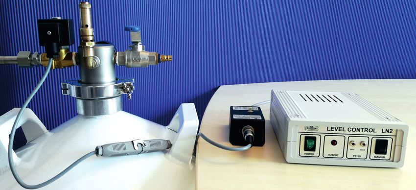
2. Aufbau und Inbetriebnahme
Beim Aufbau des Systems halten Sie bitte folgende Reihenfolge ein:
WICHTIG !!! Schutzbrille und Schutzhandschuhe tragen !!!
1. Heber mit Magnetventil auf den mit flüssigem Stickstoff gefüllten Vorratsbehälter
aufsetzen.
2. Heber mit dem Spannring fixieren und das Abgasventil schließen.
3. Kurze Zeit warten, bis sich durch die Eigenverdampfung des Stickstoffes ein
Arbeitsdruck im Behälter aufgebaut hat. Achten Sie bitte stets darauf, dass der Druck im
Behälter nicht über 0,5 bar ansteigt, gegebenenfalls zusätzlich ein Überdruckventil
anbringen.
4. Elektrische Verbindung zwischen Magnetventil und dem Regelgerät
(OUTPUT 24V-DC Dioden-Buchse auf der Geräterückseite) herstellen.
5. Minimum- und Maximumfühler (LEMO 1S Stecker) an das Regelgerät anschließen und
die Fühler im Arbeitsdewar auf die gewünschte Füllhöhe fixieren. Das Arbeitsdewargefäß
muss drucklos sein. Bitte achten Sie darauf, dass die Fühler weder die Wandung noch
andere Bauteile berühren, da dieses zu Fehlfunktionen des Regelgerätes durch
Wärmeleitung der Wandungsmaterialien führen kann.
6. Netzstecker des Regelgerätes einstecken und Gerät einschalten.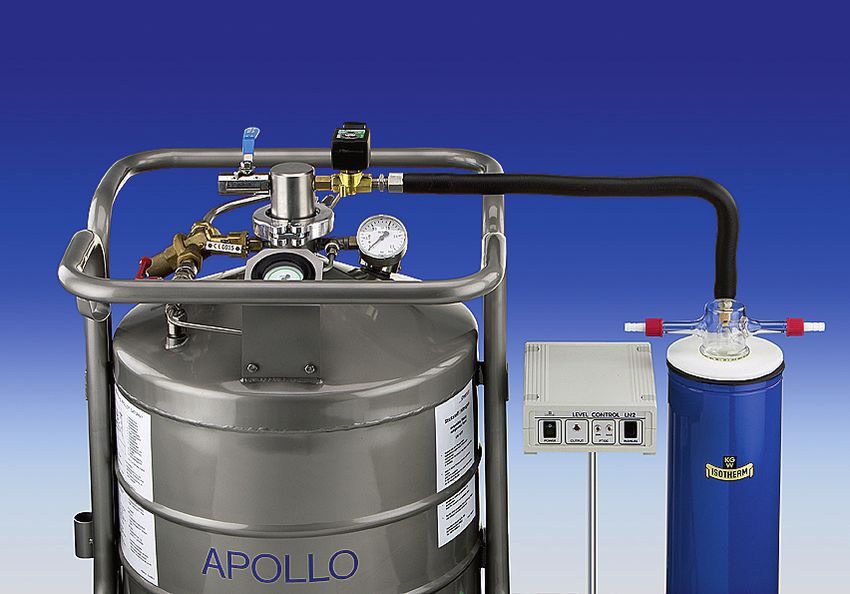
2.1 Skizze des Aufbaus

          1      2     3      4                    5                                        6

                                                       LEVEL   CONTROL       LN2

                                                                 MIN   MAX

                                           POWER   OUTPUT         PT100            MANUAL

                                                                                                           max.

                                                                                                           min.

                                                                                            Arbeitsdewar

                                                                                            Einzelteile des Systems

                                                                                            1   Druckablasshahn
              Vorratsbehälter                                                               2   Entnahmeheber
                                                                                            3   Magnetventil
                                                                                            4   Entnahmeschlauch
                                                                                            5   Regelgerät

3. Funktion
Das Regelgerät kann in zwei Regel-Betriebsarten eingesetzt werden:

3.1 Zweipunktbetrieb

Maximum-Fühler wird oberhalb des Minimum-Fühlers fixiert.

Liegt das Flüssigstickstoff-Niveau unterhalb des Minimum-Fühler, so öffnet der Regler das
Magnetventil. Aufgrund des durch Eigenverdampfung aufgebauten Druckes im Vorratstank, fließt
solange flüssiger Stickstoff in das Arbeitsdewar, bis das Flüssigstickstoff-Niveau oberhalb des
Maximum-Fühlers liegt und das Regelgerät das Magnetventil schließt.
Fällt das Niveau wieder unter den Minimum-Fühler, beginnt der Zyklus erneut.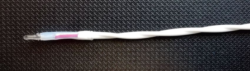
3.2 Einpunktbetrieb
Maximum-Fühler wird unterhalb des Minimum-Fühlers fixiert.
Die Regelung erfolgt um den Maximum-Fühler. Der Minimum-Fühler ist ohne Bedeutung, muss
jedoch wegen der automatischen Kabelbruchsicherung ebenfalls eingesteckt werden, oder es
wird ein Blindstecker für den Minimum-Fühler verwendet.
Liegt das Flüssigstickstoff-Niveau unterhalb des Maximum-Fühlers, so öffnet der Regler das
Magnetventil und flüssiger Stickstoff fließt solange in das Arbeitsdewar bis das Flüssigstickstoff-
Niveau oberhalb des Maximum-Fühlers liegt und der Regler das Magnetventil wieder schließt.
Der Vorgang des Öffnens und des Schließens erfolgt zeitlich verzögert. Wir empfehlen das Gerät
möglichst im Zweipunktbetrieb einzusetzen.

3.3 Manuelle Nachfüllung
Mit Hilfe des Manual-Kippschalters kann das Arbeitsdewar jederzeit auch manuell nachgefüllt
werden.
Solange der Kippschalter gedrückt wird, öffnet der Regler das Magnetventil und flüssiger
Stickstoff fließt in das Arbeitsdewar.

3.4 Optische Anzeige des Nachfüllvorganges
Der Nachfüllvorgang wird an der Frontplatte des Reglers angezeigt.
Das eingesetzte Magnetventil ist aus Sicherheitsgründen selbstschließend, d.h. das Ventil bleibt
im spannungslosen Fall geschlossen.
Solange der Magnetventilausgang "OUTPUT" unter Spannung steht und das Magnetventil
geöffnet ist, leuchtet das Anzeigelämpchen "OUTPUT" rot auf.

3.5 Automatische Kabelbruchsicherung
Das Gerät verfügt über eine automatische Fühler-Kabelbruchsicherung.
In folgenden Fällen löst das Gerät optisch (rotes Blinklicht) und akustisch (Pfeifton)
Alarm aus:
1.     Fühler - Stecker ist nicht ordnungsgemäß eingesteckt.
2.     Fühlerleitung ist defekt.
3.     PT 100 - Fühler ist defekt.

4. Wartung und Reinigung
Das Gerät ist wartungsfrei. Es darf im Reparaturfall nur von einem Elektronik- Fachmann geöffnet
werden. Bitte senden Sie das Gerät zur Reparatur an den Hersteller.
Gereinigt werden darf das Gerät nur mit Wasser und einem tensidhaltigen Waschmittelzusatz.
Verwenden Sie dazu ein feuchtes Tuch und achten Sie darauf, dass kein Wasser in das Innere des
Gerätes eindringt.
5. Fehleranalyse
Das Gerät arbeitet im allgemeinen fehlerfrei. Treten Störungen auf, so gehen Sie bitte
nach folgendem Schema auf Fehlersuche.

   Festgestellter Fehler          Mögliche Ursache                    Fehlerbeseitigung

Beim Einschalten leuchtet - Steckdose ohne                    - Netzspannung herstellen
grünes Lämpchen nicht     Spannungsversorgung

(keine Spannungsversorg.) - Netzstecker nicht eingesteckt
                                                        - Netzstecker einstecken

Beim Einschalten ertönt     - Fühler-Stecker nicht    - Fühler-Stecker einstecken
Pfeifton                    ordnungsgemäß eingesteckt

(Kabelbruchsicherung)                                         - Fühlerwiderstand prüfen,
                            - Fühlerleitung ist defekt
                                                               ggf. Hersteller kontaktieren
                            - PT 100 Fühler ist defekt
                                                               (Widerstand der Fühler
                                                              bei 20°C ca. 110
                                                                             W (Messpunkte siehe
                                                              Steckerbelegung)

 Magnetventil schaltet nicht- Grünes Lämpchen (Power)         - siehe oben
                             leuchtet nicht
                            - Gerät ist nicht eingeschaltet - Gerät einschalten (Power)
                             - Fühler berührt Wandung         - Fühler so fixieren, dass er keine
                                                              Wandung berührt.
                              oder andere Bauteile.

                                                              - Arbeitsdewar ändern
                             - Arbeitsdewarist nicht
                              drucklos
                                                              - Spannung OUTPUT prüfen,
                             - Magnetventil schaltet nicht,
                                                               ggf. Hersteller kontaktieren
                              defekt
                                                               (Bei gedrücktem Manual
                                                               Schalter: Spannung am
                                                               Magnetventil-Ausgang ca. 24V DC

Falls keine der genannten Maßnahmen zum Erfolg führt, so wenden Sie sich bitte an
den Hersteller.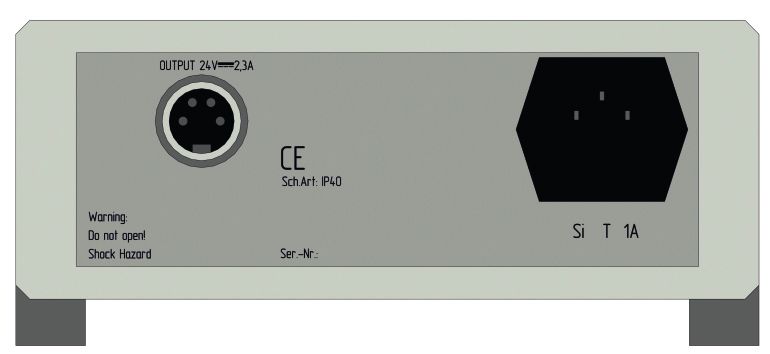
6. LN2 Niveauregelgerät
Art. Nr.
- LN2 Niveauregelgerät mit 1301L
PT 100 Lemo Steckverbinder für
LN2 Magnetventile mit 24 V DC
Lieferbares Zubehör
Art. Nr.
- Temperatur Fühler PT 100, Kabellänge 2 Meter mit Lemo-Stecker 1302L
-Temperaturfühler inklusive Lemo-Stecker metallgekapselt, 1302ML-“Länge“
Länge bitte angeben
Länge
67,60 mm
-Verbindungskabel für Temperaturfühler metallgekapselt, 1302M-KL
Länge 2,5 Meter
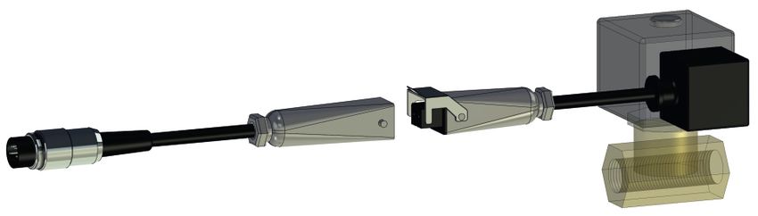
-Verbindungskabel Magnetventil einteilig, Länge 2Meter 1303L-K
-Verbindungskabel Magnetventil zweiteilig, Länge 2Meter 1303L-K2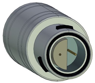
Lieferbares Zubehör

- Blindstecker                                                              1302LB

- Magnetventil für flüssigen Stickstoff ( 24V DC 50 Hz )                    1303-DC

- Flüssig-Stickstoff-Entnahmeheber (Typ EK) mit Magnetventil                1304L
  ohne Sicherheitsarmaturen

- Flüssig-Stickstoff-Entnahmeheber (Typ EKI) mit Magnetventil               1305L
  mit Sicherheitsarmaturen

- Flüssig-Stickstoff-Vorratsbehälter aus Aluminium oder Edelstahl           Auf Anfrage
 Katalog anfordern oder unter https://kgw-isotherm.de/kryobehaelter-main/

- Arbeitsdewargefäße aus Glas oder Edelstahl                                Auf Anfrage
 Katalog anfordern oder unter https://kgw-isotherm.de/dewargefaesse-main/
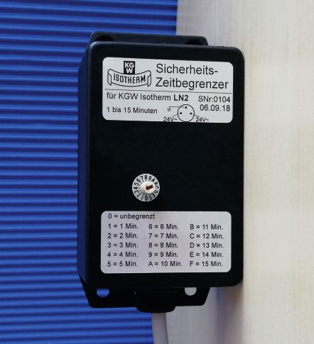
Sicherheits-Zeitbegrenzer für automatische LN2-Niveauregulierungssysteme

Bei vielen kryotechnischen Anwendungen, wie Schrumpfen von Wellen und Buchsen in LN2,
Tiefkühlen von Bauteilen oder biologischen Proben, Einsetzen von LN2 als Kühlmittel bei
Kühlfallen, Kalibrieren von Fühler in LN2, usw., werden automatische LN2 Niveauregelgeräte
Typ „Level Control LN2" von KGW-ISOTHERM eingesetzt.

Der „Level Control LN2" arbeitet wie folgt: Sinkt der LN2-Pegel unterhalb des Minimum-Fühlers,
wird ein Signal an den „Level Control LN2" gesendet. Der „Level Control LN2" öffnet dann ein
24 Volt LN2-Magnetventil, das am Entnahmeheber des LN2-Vorratsbehälters angeschlossen
ist. Durch den im LN2-Vorratsbehälter vorhandenen Überdruck wird das LN2 aus dem Behälter
herausgedrückt und durch eine Transferleitung zum Arbeitsdewargefäß geleitet. Das
einfließende LN2 hebt den Flüssigkeitsspiegel an, bis der Maximum-Fühler in das LN2
eintaucht. Der Maximum-Fühler wird dadurch abgekühlt und gibt ein Signal an den „Level
Control LN2". Dieser schaltet daraufhin das Magnetventil stromlos, so dass dieses schließt und
die LN2 -Versorgung unterbricht.

Werden diese Fühler nicht ausreichend gesichert, so besteht die Möglichkeit, dass die Fühler
Ihre Lage verändern oder ganz aus dem zu befüllenden Arbeitsdewargefäß herausfallen. Das
hätte zur Folge, dass dar „Level Control LN2" das LN2-Magnetventil nicht mehr schließt und
permanent LN2 aus dem Lagerbehälter gefördert wird. Im Extremfall könnte sich somit der
komplette LN2 Lager -behälter entleeren oder der flüssige Stickstoff über das zu befüllende
Arbeitsdewargefäß laufen.

Um ein komplettes Auslaufen des LN2 Vorratsbehälters zu verhindern, kann zwischen dem
„Level Control LN2" und dem Magnetventil ein Sicherheits-Zeitbegrenzer eingesetzt werden.
Dieser Sicherheits-Zeitbegrenzer schließt das LN2-Magnetventil nach Ablauf der eingestellten
Maximalbefüllzeit. Wenn eine Befüllzeit für die LN2-Niveauregulierung 3 Minuten dauert, könnte
man auf dem Sicherheits-Zeitbegrenzer z. B. 4 Minuten einstellen. Ist die Niveauregulierung
nach       4 Minuten nicht abgeschlossen, so unterbricht der Sicherheits-Zeitbegrenzer die
Stromversorgung des Magnetventils und dieses wird automatisch geschlossen.

Der Sicherheits-Zeitbegrenzer macht keinen automatischen Reset, sondern muss manuell
durch den Anwender zurückgesetzt werden. Hierzu muss der „Level Control LN2" für
mindestens 5 Minute ausgeschaltet werden. Anschließend kann der „Level Control LN2" durch
einschalten wieder aktiviert werden.

Der Sicherheits-Zeitbegrenzer kann nachträglich an jedes bereits vorhandene KGW-
ISOTHERM „Level Control LN2" Gerät angeschlossen werden, um die Betriebssicherheit Ihrer
Anlage zu optimieren.
8
                                                                                                                                7
                                                                                                  LEVEL CONTOL LN2

                                           Zeitbegrenzer
                                           Sicherheits-

                                                           2=2 Min 7=7 Min C=12 Min
                                                           3=3 Min 8=8 Min D=13 Min

                                                           5=5 Min A=10 Min F=15 Min
                                                           1=1 Min 6=6 Min B=11 Min

                                                           4=4 Min 9=9 Min E=14 Min
                                                                                                         MIN   MAX

                                                           0= unbegrenzt
                                                                                        POWER   OUTPUT    PT 100     MANUAL

                     3
                                4

                                                                                                                                     1) LN2-Vorratsbehälter
          2                                                                                                                          2) Entnahmeheber
                                                                                                                                     3) LN2-Magnetventil
                                                                                                                                     4) Transferleitung
                                                                                                                                     5) Arbeitsdewar
                                                                                                                                     6) Minimum-/ Maximum-Fühler
                                                                                                                                     7) Level Control LN2
                                                                                                                                     8) Sicherheits-Zeitbegrenzer
                                                                                                                                6
1

                                                                                                                                 5
                                                                                                Max

                                                                                                    Min

                                                                                       LN2

                   Aufbau und Ablauf
    Zuerst ermittelt man die Nachfüllzeit zwischen dem
    Minimum- und Maximumfühler (z. B. 3 Minuten)

    Anschließend wird der Sicherheits-Zeitbegrenzer zwischen
    dem „Level Control LN2" und dem Magnetventil eingebaut.

    Bei der Erstbefüllung des Arbeitsdewargefäßes muss die                                                                    Zeiteinstelldrehknopf für den
    Zeitbegrenzung auf 0 gesetzt werden und das Gefäß wird                                                                     Sicherheits-Zeitbegrenzer
    bis über den Miniumfühler befüllt.

    Danach wird die Niveauregelung kurzzeitig abgeschaltet.
    Die Zeitbegrenzung wird eingestellt. (z. B. eine Minute
    länger als die Nachfüllzeit zwischen Min- und Max-Fühler)

    Jetzt wird die Niveauregelung erneut gestartet und diese
    läuft dann mit der Überwachung durch den Sicherheits-
    Zeitbegrenzer.

                Technische Daten des
              Sicherheits-Zeitbegrenzer
    1) 24 Volt AC
    2) Zeiteinstellung 1 bis 15 Minuten
    3) Diodenstecker 3-polig zum Regelgerät
    4) Diodenbuchse 3-polig zum Magnetventil

    KGW Best.Nr. 1307L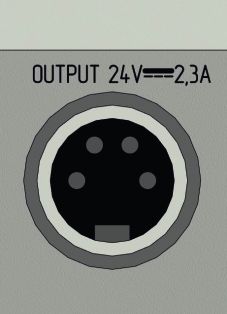
7. Steckerbelegung
Temperatur-Fühler LN2 Magnet-Ventil
LEMO S1 Vierpol-Diodenstecker
Pt100 Magnetventil
PE
+ -
2 3
1 4
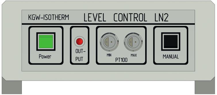
8. Frontseite
1. Netzschalter mit grüner 1 2 3 4 5
Leuchtanzeige
2. Magnetventil-Funktionsanzeige
Alarmanzeige (Blinklicht)
3. Minimum-Fühler-Buchse
4. Maximum- Fühler- Buchse
5. Taster für manuelle Befüllung Frontseite
6 7
Rückseite
6. Magnetventil-Anschluss
7. NetzkabelTechnische Daten
9.1 Regelgerät
Abmessung B x H x T : 160 x 75 x 200 mm
Gewicht : 2,5 kg
Netzspannung : 230V ~ 50 Hz und 115V ~ 60Hz.
Sicherung : 0,5 Atr.
Anschlüsse : Frontseite - Min - Fühler (LEMO 1S Buchse)
- Max - Fühler (LEMO 1S Buchse)
: Rückseite - Magnetventil (Dioden-Buchse)
24 V DC
Schutzart : IP 40
Umgebungsbedingungen : 10° bis 30°C, max. 80% rel. Feuchte
Prüfzeichen : CE
9.2 Minimum-, Maximum- Fühler
Minimum-Fühler gelb gekennzeichnet
Typ : PT 100
Klasse :B
Widerstand bei 20°C : ca. 110 W
Anschluss : LEMO 1S
9.3 Magnetventil ( Zubehör )
Spannungsversorgung : 24V DC
Funktion : selbstschließend
Medium : zugelassen für flüssigen Stickstoff
Anschluss : Diodenbuchse 4-polig
10. Garantie
Bei sachgemäßer Handhabung gewähren wir eine Garantie von 12 Monaten. Die Garantie umfasst
maximal den Einkaufswert des Gerätes. Im Garantiefall wenden Sie sich bitte an den Hersteller.Germany
KGW - ISOTHERM 76185 Karlsruhe
Gablonzer Straße 6
Tel. 0049 / 721 / 95897-0
Fax. 0049 / 721 / 95897-77
eMail:info@kgw-isotherm.de
Internet: www.kgw-isotherm.de
Operating Instructions Level controlling device
for liquid nitrogen
LEVEL CONTROL LN21. Unpacking and Setting Up
Please unpack the appliance carefully and look for damages. It is important that eventual
transport damages are already recognised upon unpacking. If needed an immediate factual
statement will be required. Contact the manufacturer for this purpose.
Look up the admissible environmental conditions from the technical data.
Use only approved temperature probes and LN2 solenoid-controlled valves (electro
valves)
2. Mounting and Commissioning
When mounting the system please keep the following order of procedure:
IMPORTANT !!! Wear protective glasses and protective gloves !!!
1. Set siphon with electro valve onto the reservoir filled with liquid nitrogen.
2. Fix siphon with straining ring and close the off-gas valve.
3. Wait for a while until a working pressure has built up in the reservoir due to the self-
vaporisation of the liquid nitrogen. Please always pay attention that the pressure inside
of the reservoir does not surpasses 0.5 bar, attach an overpressure valve, if needed.
4. Establish the electrical connection between the electro valve and the controlling unit
(OUTPUT 24V-DC diode bushing on rear side of the instrument).
5. Connect probes for minimum and maximum (LEMO plug) to the controlling unit and fix
the probes in the working Dewar vessel to the desired filling height. The working Dewar
vessel must be without pressure.
Please pay attention that the probes neither touch the walls nor other component parts,
as this can lead to failing functions of the controlling unit because of thermal conduction
of the wall materials.
6. Insert mains plug of the controlling unit and switch it on.2.1 Sketch of the mounting structure
1 2 3 4 5 6
Max-probe
Min-probe
Components of the system
1 Pressure outlet cock
2 Transfer siphon
3 LN2 electro valve
4 Transfer hose
5 Controlling unit
6 Min - Max. Probe PT 100
3. Function
The controlling unit can be utilised in two regulation operating modes:
3.1 Dual-mode Control
The maximum probe is fixed above the minimum probe.
If the liquid nitrogen level is under the minimum probe, the regulator will open the electro valve.
Due to the pressure built up by self-evaporation in the reservoir, liquid nitrogen will continue
flowing into the working Dewar, until the liquid nitrogen level will be above the maximum probe,
and the controlling unit will close the electro valve.
If the level sinks under the minimum probe the cycle will start again.3.2 Mono-mode Operation
The maximum probe is fixed under the minimum probe.
The regulation is effected around the maximum probe. The minimum probe is insignificant;
because of the automatic cable break safety device it must, however, also be inserted, or a
dummy plug must be used for the minimum probe.
If the liquid nitrogen level is under the maximum probe, liquid nitrogen will continue flowing
into the working Dewar, until the liquid nitrogen level will be above the maximum probe, and
the controlling unit will close the electro valve again. The procedure of opening and closing is
done with a time lag. We recommend to use the instrument in dual mode operation, if
possible.
3.3 Manual Refilling
The working Dewar can be refilled also manually at any time by means of the flip switch.
As long as the flip switch is pressed, the regulator opens the electro valve and liquid nitrogen
flows into the working Dewar.
3.4 Optical Indication of the Refill Procedure
The refill procedure is indicated on the front plate of the controlling unit.
The applied electro valve is self-closing for safety reasons, i.e. the valve stays closed in a
tensionless case.
As long as the electro valve output is under tension and the electro valve is opened, the
indicator lamp "OUTPUT" will be illuminated red.
3.5 Automatic Cable Break Safety Device
The unit has an automatic probe cable break safety device.
In the following cases the instrument will release an alarm optically (red blinking light) and
acoustically (whistle sound):
1. Probe plug is not inserted orderly.
2. Probe line is defective.
3. PT 100 probe is defective.
4. Maintenance and Cleaning
The instrument is maintenance-free. In a case of repair it may only be opened by an
electronics expert. Please send the unit to the manufacturer for repair.
The unit must only be cleaned with water and a tenside detergent additive. Use a damp cloth
hereto and pay attention that no water will penetrate into the interior of the unit.5. Error Analysis
The unit generally works without failure. If disturbances occur, please look for faults
according to the following method.
Faults Found Possible Causes Remedy of Faults
Green lamp is not - Probe plug not orderly - Insert probe plug
illuminated inserted
upon switch-on - Check probe resistance, if
- Probe line is defective necessary contact manufacturer
(No tension
supplied) - PT 100 probe is defective - resistance of the probes at
20°C about 110Ohm Measuring
points see plug assignment
Whistling tone - Probe plug not orderly - Insert probe plug
sounds upon inserted
switch-on - Check probe resistance, if
(Cable break - Probe line is defective necessary contact manufacturer
device)
- PT 100 probe is defective - resistance of the probes at
20°C about 110Ohm Measuring
points see plug assignment
Electro valve (LN2 - Green lamp (power) is not - See above
solenoid-controlled illuminated
valve) does not
switch - Instrument is not switched - Switch appliance on (power)
on
- Probe touches wall or - Fix probe in a way in which it
other will not touch a wall.
component parts
- Change working Dewar
- Working Dewar is not
pressure less
- Check tension OUTPUT, if
- Electro valve defective necessary contact manufacturer
With hand switch pressed:
If none of the mentioned measures is successful, please contact the manufacturer.6. LN2 Level Control
Art. Nr.
- LN2 Level Control with 1301L
PT 100 LEMO connectors
for LN2 magnetic valves
Available Accessories
Art. Nr.
- Temperature sensor PT 100 length: 2m with LEMO plug 1302L
-Metal encapsulated sensor PT 100 length: 2,5m with LEMO plug 1302ML-“length“
length
67,60 mm
-Connection cable (2,5m) for metal-encapsulated sensors 1302M-KL
-Electrical connection cable (2 metres) 1303L-K
from LN2-Contoller to LN2 solenoid valve
-Electrical connection cable (2 metres) 1303L-K2
from LN2-Contoller to LN2 solenoid valve
two-parted with plug-in couplingAvailable Accessories - Blind plug 1302LB - Solenoid valve 24 V / DC 1303-DC - LN2 transfer siphon with solenoid valve type 1 (EK) 1304L without safety equipment - LN2 transfer siphon with solenoid valve type 2 (EKI) 1305L with safety equipment - LN2-storage container made of AL or stainless steel Auf Anfrage Request catalog or at https://kgw-isotherm.com/cryo-vessels-main/ - Working dewar made of glass or stainless steel Auf Anfrage Request catalog or at https://kgw-isotherm.com/dewarflasks-main/
Safety timer for automatic LN2 - niveau level controller

Automatic "Level Control LN2" type LN2 level regulation devices by KGW-ISOTHERM are used in
many cryotechnical applications, such as the shrinking of shafts and bushes in LN2, deep-
freezing of components or biological samples, use of LN2 as a coolant for cold traps, calibration
of sensors in LN2, etc.

The "Level Control LN2" works as follows: If the LN2 level drops below the minimum sensor, a
signal is sent to the "Level Control LN2". The "Level Control LN2" then opens a 24-volt LN2
magnet valve that is connected to the siphon of the LN2 storage tank. Because of the
overpressure in the LN2 storage tank, the LN2 is forced out of the tank and into the working
Dewar flask through a transfer line. The incoming LN2 raises the liquid level until the maximum
sensor is immersed in the LN2. This has a cooling effect on the maximum level sensor, which
then transmits a signal to the "Level Control LN2", which in turn switches off the magnet valve,
and this then closes and the LN2 supply is interrupted.

If these sensors are not sufficiently secured, it's possible for them to change their position or to
completely drop out of the working Dewar flask that is to be filled. This would result in the "Level
Control LN2" no longer closing the LN2-magnet valve and LN2 being emitted permanently from
the storage tank. In extreme cases, this could result in the complete LN2 storage tank being
emptied or the liquid nitrogen spilling over in the working Dewar flask to be filled.

To prevent the LN2 storage tank from being emptied completely, a safety timer can be inserted
between the "Level Control LN2" and the magnet valve. This safety timer closes the LN2magnet
valve after the set maximum filling time has expired. If the filling time for the LN2 level regulation
takes 3 minutes, the safety timer could be set to, for example, 4 minutes. If the level regulation is
not concluded after 4 minutes, then the safety time-limiter interrupts the power supply of the
magnet valve and it is closed automatically.

The safety timer does not perform an automatic reset, but instead must be reset manually by the
user. To do this, the "Level Control LN2" must be switched off for at least 5 minute. Next, the
"Level Control LN2" can be re-activated by switching it on again.

The safety timer can be retrofitted to any installed KGW-ISOTHERM "Level Control LN2" device
to optimise the operational safety of your system.
8
                                                                                                                                7
                                                                                                    LEVEL CONTOL LN2

                                             Zeitbegrenzer
                                             Sicherheits-

                                                             2=2 Min 7=7 Min C=12 Min
                                                             3=3 Min 8=8 Min D=13 Min

                                                             5=5 Min A=10 Min F=15 Min
                                                             1=1 Min 6=6 Min B=11 Min

                                                             4=4 Min 9=9 Min E=14 Min
                                                                                                           MIN   MAX

                                                             0= unbegrenzt
                                                                                          POWER   OUTPUT    PT 100     MANUAL

                     3
                                 4

                                                                                                                                    1) LN2 storage tank
         2                                                                                                                          2) Siphon
                                                                                                                                    3) LN2 magnet valve
                                                                                                                                    4) Transfer line
                                                                                                                                    5) Dewar flask
                                                                                                                                    6) Minimum/maximum sensor
                                                                                                                                    7) Level Control LN2
                                                                                                                                    8) Safety timer
                                                                                                                                6
1

                                                                                                                                5
                                                                                                  Max

                                                                                                      Min

                                                                                         LN2

               Setup and procedure
First, the filling time between the minimum and maximum                                                                         Time adjustment knob for
sensors needs to be determined (e.g. 3 minutes).                                                                                    the safety timer
Next, the safety timer is installed between the "Level Control
LN2" and the magnet valve.

When initially filling the Dewar flask, the time limit must be
set to 0 and the device must be filled to a level above the
minimum sensor.

After this, the level regulation is briefly switched off. The
time limit is set (e.g. one minute longer than the filling time
between the minimum and maximum sensors).

Next, the level regulation is started again and will run while
being monitored by the safety timer.

             Technical data of the
                Safety Timer
1) 24 volt AC
2) Time setting for 1 to 15 minutes
3) 3-pole diode connector to the control device
4) 3-pole diode bush to the magnet valve

KGW Art. No. 1307L
7. Plug Assignment
Temperature probe LN2 magenetic valve
LEMO 1S plug Four-pole diode plug
Pt100 magnetic valve
PE
+ -
2 3
1 4
1 2 3 4 5
8. Front and Rear Side
1 Mains switch with green
Illuminous indicator
2 Electro valve function indicator,
Alarm indicator (blinking light)
3 Minimum probe bushing
4 Maximum probe bushing
5 Flip switch for manual filling
6 7
Rear Side
6 Electro valve connection
7 Mains supply9. Technical Characteristics
9.1 Controlling device
Dimensions w x h x d : 160 x 75 x 200 mm
Weight : 2,5 kg
Mains tension : 230V ~ 50 Hz and 115V ~ 60Hz.
Protective fuse : 0.5 A time-lag fuse
Connections : front side - min probe (LEMO 1S bush)
- max probe (LEMO 1S bush)
: rear side - electro valve 24V DC (diode bush)
Protection type : IP 40
Environmental conditions : 10° to 30°C, max 80% rel. humidity
Mark of conformity : CE
9.2 Minimum, Maximum Probe
Minimum-probe yellow marked
Type : PT 100
Class :B
Resistance at 20°C : about 110 Ohm
Connection : LEMO 1S
9.3 Electro valve ( accessory )
Tension supply : 24V DC
Function : self-closing
Medium : approved for liquid nitrogen
Connection : diode bushing 4-pole
10. Guarantee
With proper handling we grant a guarantee of 12 months. The guarantee comprises at
maximum the purchase value of the unit. In a case of guarantee please contact the
manufacturer.Sie können auch lesen