MSDTM FKD-MVTM DSCTM MEDIUM VOLTAGE CAPACITORS AND REACTORS - THE ECO-FRIENDLY ALTERNATIVE
←
→
Transkription von Seiteninhalten
Wenn Ihr Browser die Seite nicht korrekt rendert, bitte, lesen Sie den Inhalt der Seite unten
www.electronicon.com

                       MSD FKD-MV DSC
                           TM             TM      TM

                           MEDIUM VOLTAGE CAPACITORS
                                       AND REACTORS

                        THE ECO-FRIENDLY ALTERNATIVE
www.electronicon.com

                                       E93 DSC       TM

                                     SURGE PROTECTION
                                            CAPACITOR

        WHO SAID IT HAS TO LOOK LIKE A SURGE CAPACITOR?
MSD     TM

SELF-HEALING MEDIUM VOLTAGE
CAPACITORS IN DRY TECHNOLOGY
SELBSTHEILENDE MITTELSPANNUNGSKONDENSATOREN
IN TROCKENTECHNOLOGIE

FKD-MV        TM

DETUNING REACTORS FOR MEDIUM
VOLTAGE CAPACITORS
FILTERKREISDROSSELN FÜR MITTELSPANNUNGSKONDENSATOREN

DSC    TM

SELF-HEALING SURGE PROTECTION
CAPACITORS IN DRY TECHNOLOGY
                                                           ISSUE_AUSGABE - 2022

SELBSTHEILENDE ÜBERSPANNUNGSSCHUTZKONDENSATOREN
IN TROCKENTECHNOLOGIE

ELECTRONICON KONDENSATOREN GMBH GERA · GERMANY
                                                       3
4
MSDTM
MSD – The Clever Alternative MSD – Die clevere Alternative
Self-healing dielectric: No short circuits Selbstheilendes Dielektrikum: keine Kurzschlüsse
> Short-circuit currents are not possible due to the high-resistance fault > Wegen des hochohmigen Fehlerbildes des selbstheilenden Dielektri-
characteristic of the self-healing dielectric. Special, short-circuit kums sind keine Kurzschlussströme möglich. Spezielle, kurzschluss-
current limiting capacitor fuses are not necessary. Functional switching strombegrenzende Kondensatorsicherungen sind nicht erforderlich. Für
devices are sufficient for tripping. die Auslösung sind Betriebsschaltgeräte ausreichend.
Reliable monitoring by pressure switch Zuverlässige Überwachung durch Druckschalter
> The costs of the monitoring circuit are very low. It is sufficient to control > Geringe Kosten für die Überwachungsschaltung. Es genügt, die Auslöse-
the tripping function of the switch via the normally closed contact of funktion des vorgelagerten Schaltgerätes über den Öffnerkontakt der
the pressure monitor and lock it against re-connection. Drucküberwachung anzusteuern und gegen Wiedereinschaltung zu ver-
riegeln.
> Every enclosure is monitored separately. Any number of individual > Jedes Gehäuse wird einzeln überwacht. Beliebig viele Einzelkondensa-
capacitors can be grouped together for protection purposes. toren können schutztechnisch zusammengefasst werden.
Asymmetries are impossible Unsymmetrien faktisch ausgeschlossen
> As a consequence of the different partial failure mode of MSD capaci- > Infolge des andersartigen Ausfallverhaltens selbstheilender Konden-
tors compared to that of Allfilm capacitors, the possibility of current satoren ist das Risiko von Unsymmetrie praktisch ausgeschlossen.
imbalance in the three phases can be ruled out almost completely. Damit erübrigt sich eine Überwachung des Sternpunktes, wodurch sich
Hence monitoring of the star point is unnecessary which leads to further der Installationsaufwand wesentlich verringert.
reduction of installation cost.
conventional installation of 1ph capacitors with asymmetry protection MSD installation – simple and economical
herkömmliche Installation 1 ph Kondensatoren mit Unsymmetrieschutz MSD-Installation – einfach und sparsam
OLD: L1 NEW: L1
L2 L2
L3 L3
Fuses
Asymmetry protection relay Sicherung Fuses
Unsymmetrieschutz Contactor Sicherungen
Schütz Contactor
APR
Schutz
C1 C2 C C4 C4 C5 MSD
Pressure switch
INTRODUCTION_EINLEITUNG_MSD
Druckwächter
No liquids, no environmental risk Keine Flüssigkeiten, kein Umweltrisiko
> Oil sumps are unnecessary due to the dry design; no oil which could > Dank Trockenaufbau keine Ölauffangwannen erforderlich. Keine grund-
pollute the local environment. No disposal problems at the end of use- wassergefährdenden Öle, damit auch kein Entsorgungsproblem am Ende
ful service live. der Gebrauchsdauer.
Long-term stable capacitance Langzeitstabile Kapazität
C
> Reliability during applications in de-tuned and tuned filters and double > Sicherheit beim Einsatz in verstimmten und abgestimmten Filterkreis- t
filters by anlagen sowie Doppelfiltern durch
• long term stability of capacitance • hohe Langzeitstabilität
• very small capacitance tolerances up to ±2.5% • sehr enge Kapazitätstoleranzen bis zu ±2,5%
5
Design and characteristics Aufbau und Eigenschaften
The MSD technology is based on the logical development of proven self-
healing technology for low-voltage power capacitors. It also permits the
economic manufacture of medium voltage capacitors without employing
inflammable and environmentally critical fluid oil fillings. The actual ac- winding element Wickelkörper
tive capacitor element consists of a large number of high-quality, self-
healing round MKP elements, which are wired to each other and installed polypropylene film, uncoated
Polypropylenfolie unmetallisiert
in a steel enclosure.
Die MSD-Technik basiert auf der konsequenten Weiterentwicklung der be-
währten Technologie von selbstheilenden Niederspannungs-Leistungskon contact layer Stirnkontaktschicht
densatoren. Sie gestattet es, nun auch Mittelspannungskondensatoren
ohne brennbare und umweltkritische flüssige Ölfüllung wirtschaftlich polypropylene film, metal deposit on one side
Polypropylenfolie, einseitig metallisiert
herzustellen. Der eigentliche Aktivteil des Kondensators besteht aus einer
größeren Zahl hochwertiger, selbstheilender MKP-Rundwickel, die, mitein-
ander verschaltet, als Paket in ein Stahlgehäuse eingebaut werden.
Our MSD capacitors are filled with solid materials, i.e. dry, instead of Statt mit brennbarer Flüssigkeit wie bei Allfilm-Mittelspannungskon-
combustible liquid as with Allfilm medium voltage capacitors. densatoren sind unsere MSD-Kondensatoren mit Feststoffen gefüllt,
also trocken.
High-quality insulation between the active elements and the enclosure Durch ein spezielles Verfahren wird eine qualitativ hochwertige Isolation
is achieved using a special process, which is designed and tested to suit zwischen Aktivteil und Gehäuse erreicht, die entsprechend den Anfor-
the requirements for the nominal insulation voltage of the capacitor. This derungen der Nennisolationsspannung des Kondensators ausgelegt und
special insulation is of crucial importance for the safe operation of the geprüft ist. Diese spezielle Isolation ist für die sichere Funktion der
internal pressure monitor: self-healing capacitors are not (yet) covered Innendrucküberwachung von ausschlaggebender Bedeutung: obwohl selbst-
by current standards for medium voltage capacitors, such as IEC 60871, heilende Kondensatoren von den derzeit gültigen Standards für Mittel-
however, our MSD series fulfils all electrical and safety requirements of spannungskondensatoren, wie z.B. IEC 60871, (noch) nicht erfasst werden,
these standards. It has to be noted that the MSD capacitors – like any self erfüllt unsere MSD-Serie alle elektrischen und sicherheitstechnischen
healing capacitor – do not produce short circuits and can therefore not be Anforderungen dieser Standards. Es ist jedoch zu beachten, dass die MSD-
disconnected from the system by internal or external blow-out fuses. This Kondensatoren – wie alle selbstheilenden Kondensatoren – im Fehlerfall
task is performed by integrated over-pressure switches as described in the keine Kurzschlüsse erzeugen und somit nicht durch interne oder externe
standards applicable to capacitors for power electronics and for inductive Schmelzsicherungen vom Netz getrennt werden können. Diese Aufgabe
heating. (VDE-EN 61071 and VDE-EN 60110). Note that, once the pressure übernimmt ein integrierter Überdruckschalter wie in den Normen für
switch has caused disconnection of capacitor, it must be locked externally Kondensatoren der Leistungselektronik und für induktive Erwärmung be-
against re-connection. schrieben. (VDE-EN 61071 sowie VDE-EN 60110). Achtung: Nachdem der
Druckschalter die Abschaltung eines Kondensators erzwungen hat, muss
jener extern gegen Wiedereinschaltung verriegelt werden.
Economic viability Wirtschaftlichkeit
INTRODUCTION_EINLEITUNG_MSD
The pure capacitor manufacturing costs are slightly higher than former Bedingt durch den Einsatz besonders hochwertiger Materialien und einen
Allfilm capacitors as a result of the employment of especially high quality speziellen Fertigungsprozess sind die reinen Kondensator-Herstellkosten
materials and a special production process. etwas höher als bei herkömmlichen Allfilm-Kondensatoren.
If the total system costs including electrical protection systems such Werden jedoch die gesamten Anlagenkosten einschließlich elektrischer
as asymmetry protection, fire protection and environmental protection Schutztechnik wie Unsymmetrieschutz, Brandschutz und Umweltschutz-
measures are also considered, then significant cost benefits are achieved maßnahmen am Aufstellort und spätere Entsorgungskosten hinzugerechnet,
in the small to medium power range of 50...6000 kvar. MSD is also generally ergeben sich deutliche Kostenvorteile im Bereich kleiner bis mittlerer Leis-
interesting for larger powers in the voltage range up to 12kV. Oil-filled tungen von 50 bis etwa 6.000 kvar. Grundsätzlich ist MSD im Spannungs-
capacitors are not permitted at locations with special fire risk, e.g. in bereich bis 12kV auch für größere Leistungen interessant. An Aufstellungs-
mines, in protected water catchment areas or drinking water pump orten mit besonderer Brandgefährdung, wie z.B. unter Tage, in Wasser-
stations, so that other alternatives are often unavailable. schutzgebieten oder Trinkwasserpumpstationen, sind ölgefüllte Konden-
satoren nicht zugelassen, so dass oft keine anderen Alternativen bestehen.
Application Anwendung
Fixed motor and transformer compensation, automatic capacitor banks, Motor- und Transformatorfestkompensation, automatische Blindleis-
mobile sub-stations, de-tuned and tuned filter circuits, in double filters, tungs-Kompensationsanlagen, mobile Umspannstationen, verstimmte und
audio frequency links and other applications in critical areas for applica- abgestimmte Filterkreise, in Doppelfiltern, Tonfrequenzankopplungen und
tion in the 1.9 to 12kV range. sonstige Anwendungen speziell im kritischen Umfeld.
6
MSD E90.***
                        for latest edition and updates                                                                                                                                                 3ph
                        check www.powercapacitors.info                                                                                                                                         2.4...3.3kV

Three phase MV Capacitors for PFC and Harmonic Filters
Dreiphasige Mittelspannungskondensatoren für Kompensation und Filter

Permitted operating voltages Zulässige Betriebsspannungen                                                      lower limit temperature . . . . . . . . . . . . . . . . . –40°C
     24h. . . . . . . . . . . . . . . . . . . . . . . . . . . . . . . . . . . . . . . UN                       untere Grenztemperatur
     12h/d. . . . . . . . . . . . . . . . . . . . . . . . . . . . . . . . . . . . . 1.1 × UN
     30min/d. . . . . . . . . . . . . . . . . . . . . . . . . . . . . . . . . . . 1.15 × UN                    Dissipation losses Verlustleistung
     5min (200×) . . . . . . . . . . . . . . . . . . . . . . . . . . . . . . . . 1.2 × UN                         Dielectric Dielektrikum . . . . . . . . . . . . . . . < 0.20 W/kvar
     1min (200×) . . . . . . . . . . . . . . . . . . . . . . . . . . . . . . . . 1.3 × UN                         Total capacitor Kondensator gesamt . . . . . < 0.25 W/kvar
     max. peak rating zulässiger Spitzenwert. . . . . . . . . . . 3 × UN
Test voltage Prüfspannung                                                                                      Life expectancy Lebensdauer (permitted failure rate_bei einer Ausfallrate 3%)
     UBB . . . . . . . . . . . . . . . . . . . . . . . . . . . . . . . . . . . . . . . AC 2 × UN                  at temperature acc. to chart . . . . . . . . . . . >100 000 h
                                                                                                                  bei Temperaturklasse lt. Tabelle
Internal connection innere Verschaltung. . . . . . . . . . . . Y
Inrush current Einschaltstrom. . . . . . . . . . . . . . . . . . . . max. 150 × IN                             Overpressure switch . . . . . . . . . . . . . . . . . . . changeover switch
Discharge resistor Entladewiderstand . . . . . . . . . . . . . . inside innen                                  Überdruckschalter                                         Wechsler 4A/250V AC
MSD E90.***
3ph
3.6...7.1kV
QC CN IN temp.categ. L×B×H a m order no.
(kvar) (µF) (A) Temp.klasse (mm) (mm) (kg) Bestell-Nr.
UN 3600V 50Hz UBG (BIL) 10/40kV
50 3 × 12.3 3×8 D 340 × 125 × 315 129 18 E90.C31-123340
100 3 × 24.6 3 × 16 D 340 × 125 × 425 129 23 E90.C42-253340
134 3 × 32.9 3 × 21.4 D 415 × 150 × 455 129 23 E90.G45-333340
150 3 × 36.8 3 × 24.1 D 415 × 150 × 455 158 40 E90.G45-373340
200 3 × 49.1 3 × 32.1 C 415 × 150 × 455 158 40 E90.G45-493340
250 3 × 61.4 3 × 40.1 C 415 × 150 × 585 158 43 E90.G58-613340
268 3 × 65.8 3 × 43 C 415 × 150 × 585 158 43 E90.G58-663341
300 3 × 73.7 3 × 48.1 B 415 × 150 × 585 158 43 E90.G58-743340
400 3 × 98.2 3 × 64.2 B 415 × 150 × 715 158 55 E90.G71-983340
UN 4160V 60Hz UBG (BIL) 24/75kV
50 3 × 7.7 3 × 6.9 D 340 × 125 × 315 129 18 E90.C31-772440
100 3 × 15.3 3 × 13.9 D 340 × 125 × 425 129 23 E90.C42-153440
150 3 × 23 3 × 20.8 D 340 × 125 × 425 129 23 E90.C42-233440
200 3 × 30.7 3 × 27.8 C 415 × 150 × 455 158 40 E90.G45-313440
250 3 × 38.3 3 × 34.7 C 415 × 150 × 455 158 40 E90.G45-383440
300 3 × 46 3 × 41.6 B 415 × 150 × 585 158 43 E90.G58-463440
UN 6600V 50Hz UBG (BIL) 20/60kV
50 3 × 3.7 3 × 4.4 D 340 × 125 × 315 129 18 E90.C31-372340
100 3 × 7.3 3 × 8.7 D 340 × 125 × 425 129 23 E90.C42-732340
150 3 × 11 3 × 13.1 D 415 × 150 × 455 158 40 E90.G45-113340
200 3 × 14.6 3 × 17.5 D 415 × 150 × 455 158 40 E90.G45-153340
250 3 × 18.3 3 × 21.9 C 415 × 150 × 585 158 43 E90.G58-183340
DATA CHARTS _DATENTABELLEN_MSD 3.6...7.1kV_3ph
300 3 × 21.9 3 × 26.2 C 415 × 150 × 585 158 43 E90.G58-223340
400 3 × 29.2 3 × 35 C 415 × 150 × 840 158 63 E90.G84-293340
UN 6600V 60Hz UBG (BIL) 20/60kV
50 3×3 3 × 4.4 D 340 × 125 × 315 129 18 E90.C31-302440
100 3 × 6.1 3 × 8.7 D 340 × 125 × 425 129 23 E90.C42-612440
150 3 × 9.1 3 × 13.1 D 340 × 125 × 425 129 23 E90.C42-912440
200 3 × 12.2 3 × 17.5 D 415 × 150 × 455 158 40 E90.G45-123440
250 3 × 15.2 3 × 21.9 C 415 × 150 × 455 158 40 E90.G45-153441
300 3 × 18.3 3 × 26.2 C 415 × 150 × 585 158 43 E90.G58-183440
UN 7100V 50Hz UBG (BIL) 20/60kV
50 3 × 3.2 3 × 4.1 D 340 × 125 × 315 129 18 E90.C31-322340
100 3 × 6.3 3 × 8.1 D 340 × 125 × 425 129 23 E90.C42-632340
130 3 × 8.2 3 × 10.5 D 415 × 150 × 455 129 23 E90.G45-822341
150 3 × 9.5 3 × 12.2 D 415 × 150 × 455 158 40 E90.G45-952340
200 3 × 12.6 3 × 16.3 D 415 × 150 × 455 158 40 E90.G45-133340
250 3 × 15.8 3 × 20.3 C 415 × 150 × 585 158 43 E90.G58-163340
260 3 × 16.4 3 × 21.1 C 415 × 150 × 585 158 43 E90.G58-163341
300 3 × 18.9 3 × 24.4 C 415 × 150 × 585 158 43 E90.G58-193340
400 3 × 25.2 3 × 32.5 C 415 × 150 × 840 158 63 E90.G84-253341
Other power and voltage ratings available on request.
8 Andere Leistungen und Nennspannungen auf Anfrage erhältlich.
MSD E90.***
                                                                                                                                            3ph
                                                                                                                                     7.2...12kV

QC         CN           IN         temp.categ.   LxBxH                a               m                  order no.
(kvar)     (µF)         (A)        Temp.klasse   (mm)                 (mm)            (kg)               Bestell-Nr.

UN 7200V 60Hz         UBG (BIL) 20/60kV
     50    3 × 2.6      3×4             D        340 × 125 × 315       129             18                E90.C31-262440
 100       3 × 5.1      3×8             D        340 × 125 × 425       129             23                E90.C42-512440
 150       3 × 7.7      3 × 12          D        415 × 150 × 455       158             40                E90.G45-772440
 200       3 × 10.2     3 × 16          D        415 × 150 × 455       158             40                E90.G45-103440
 250       3 × 12.8     3 × 20          C        415 × 150 × 585       158             43                E90.G58-133440
 300      3 × 15.4      3 × 24.1       C         415 × 150 × 585       158             43                E90.G58-153440
UN 11000V 50Hz        UBG (BIL) 28/75kV
 150       3×4          3 × 7.9         D        415 × 150 × 455       158             40                E90.G45-402341
 200       3 × 5.3      3 × 10.5        D        415 × 150 × 455       158             40                E90.G45-532340
 250       3 × 6.6      3 × 13.1        D        415 × 150 × 585       158             43                E90.G58-662340
 400       3 × 10.5     3 × 21          C        415 × 150 × 840       158             63                E90.G84-113340
 500      3 × 13.2      3 × 26.2      B          415 × 150 × 935       158             70                E90.G93-133340
UN 12000V 50Hz        UBG (BIL) 28/75kV
 134       3×3          3 × 6.4         D        415 × 150 × 455       158             40                E90.G45-302340
 150       3 × 3.3      3 × 7.2         D        415 × 150 × 455       158             40                E90.G45-332340
 200       3 × 4.4      3 × 9.6         D        415 × 150 × 455       158             40                E90.G45-442340
 250       3 × 5.5      3 × 12          D        415 × 150 × 585       158             43                E90.G58-552341
 267       3 × 5.9      3 × 12.8        D        415 × 150 × 585       158             43                E90.G58-592341
 300       3 × 6.6      3 × 14.4        D        415 × 150 × 585       158             43                E90.G58-662341
 334       3 × 7.4      3 × 16.1        C        415 × 150 × 715       158             53                E90.G71-742341
 400       3 × 8.8      3 × 19.4        C        415 × 150 × 715       158             53                E90.G84-882340
 500       3 × 11.1     3 × 24.1        B        415 × 150 × 935       158             70                E90.G93-113340

                                                                                                                                                   DATA CHARTS _DATENTABELLEN_MSD 7.2...12kV_3ph
 534      3 × 11.8      3 × 24.7      B          415 × 150 × 935       158             70                E90.G93-123340
UN 12000V 60Hz        UBG (BIL) 28/75kV
 150       3 × 2.8      3 × 7.2         D        415 × 150 × 455       158             40                E90.G45-282440
 200       3 × 3.7      3 × 9.6         D        415 × 150 × 455       158             40                E90.G45-372440
 250       3 × 4.6      3 × 12          D        415 × 150 × 585       158             43                E90.G58-462440
 300       3 × 5.5      3 × 14.4        D        415 × 150 × 585       158             43                E90.G58-552440
 400       3 × 7.4      3 × 19.4        C        415 × 150 × 715       158             53                E90.G71-742440

                                                                             Other power and voltage ratings available on request.
                                                                   Andere Leistungen und Nennspannungen auf Anfrage erhältlich.               9
MSD E90.***
                                              1ph                                                                                                                                                     for latest edition and updates
                                              6...12 kV mains                                                                                                                                       check www.powercapacitors.info

                                                            Single phase Power Capacitors for star connection in 50 Hz mains
                                                            Einphasige Leistungskondensatoren für Sternverschaltung in 50 Hz-Netzen

                                                            Permitted operating voltages Zulässige Betriebsspannungen                                                  lower limit temperature . . . . . . . . . . . . . . . . . –40°C
                                                                 24h. . . . . . . . . . . . . . . . . . . . . . . . . . . . . . . . . . . . . . UN                     untere Grenztemperatur
                                                                 12h/d. . . . . . . . . . . . . . . . . . . . . . . . . . . . . . . . . . . . 1.1 × UN
                                                                 30min/d. . . . . . . . . . . . . . . . . . . . . . . . . . . . . . . . . . 1.15 × UN                  Dissipation losses Verlustleistung
                                                                 5min (200×) . . . . . . . . . . . . . . . . . . . . . . . . . . . . . . . 1.2 × UN                       Dielectric Dielektrikum . . . . . . . . . . . . . . . < 0.20 W/kvar
                                                                 1min (200×) . . . . . . . . . . . . . . . . . . . . . . . . . . . . . . . 1.3 × UN                       Total capacitor Kondensator gesamt. . . . . < 0.25 W/kvar
                                                                 max. peak rating zulässiger Spitzenwert. . . . . . . . . . 3 × UN
                                                            Test voltage Prüfspannung                                                                                  Life expectancy Lebensdauer (permitted failure rate_bei einer Ausfallrate < 3%)
                                                                 UBB . . . . . . . . . . . . . . . . . . . . . . . . . . . . . . . . . . . . . . AC 2 × UN                at temperature acc. to chart . . . . . . . . . . . >100 000 h
                                                                                                                                                                          bei Temperaturklasse lt. Tabelle
                                                            Inrush current Einschaltstrom. . . . . . . . . . . . . . . . . . . max. 150 × IN
                                                            Discharge resistor Entladewiderstand. . . . . . . . . . . . . inside innen                                 Overpressure switch . . . . . . . . . . . . . . . . . . . changeover switch
DIMENSION DRAWINGS
MASSBILDER
Enclosure . . . . . . . . . . . . . . . . . . . . . . . steel, painted RAL 5019 Gehäusematerial. . . . . . . . . . . . . . . . . . . Stahl, lackiert RAL 5019
Terminals . . . . . . . . . . . . . . . . . . . . . . . ceramic insulators with Anschlüsse . . . . . . . . . . . . . . . . . . . . . . . Keramikisolatoren mit
threaded stud M12 × 35 Gewindebolzen M12 × 35
Imax (Terminals) . . . . . . . . . . . . . . . . . . . 100 A Imax (Anschlüsse). . . . . . . . . . . . . . . . . . . 100 A
Degree of protection . . . . . . . . . . . . . . . IP 00 Schutzgrad. . . . . . . . . . . . . . . . . . . . . . . IP 00
Humidity class . . . . . . . . . . . . . . . . . . . C Feuchteklasse. . . . . . . . . . . . . . . . . . . . . C
Creepage distances . . . . . . . . . . . . . . . 290mm Kriechstrecken. . . . . . . . . . . . . . . . . . . . 290mm
Clearance in air . . . . . . . . . . . . . . . . . . see drawing Luftstrecken. . . . . . . . . . . . . . . . . . . . . . siehe Maßbild
Dimension drawing
Maßbild
a a
M12×35
165
5
H
Druckschalter
pressure switch
20
100
13
20
60
35 B-10 DIMENSION DRAWING_MASSBILD_MSD
L B
L+96
L+57
3ph
68 13×19
20
128,5 M8×20
a
Clearance in air Luftstrecken
M12×35
68 13×19 B × L (mm) 3phase (mm) 1phase (mm)
1ph
125 × 340 90 130
20
150 × 415 125 130
207,5 M8×20
11MSD E90.***
The Most Efficient Protection Device: Die effizienteste Schutzeinrichtung:
Pressure Switch Druckschalter
The failure of self-healing capacitors is usually accompanied by the thermal Der Ausfall selbstheilender Kondensatoren geht in der Regel mit einer
disintegration of dielectric material, causing a gradual rise of the internal pres- thermischen Zersetzung dielektrischer Materialien und einem schritt-
sure. The period during which such rise of pressure can happen ranges from weisen Druckanstieg im Kondensatorinneren einher. Dies kann sich über
several seconds to hours or days. Since the dissipation products of polypro- einige Sekunden bis hin zu Stunden oder sogar Tage erstrecken. Da die
pylene contain explosive organic gasses, a controlled pressure relief into the Zersetzungsprodukte von Polypropylen explosive organische Gase ent-
surrounding atmosphere, e.g. through pressure disks or relief valves, may of- halten, kann ein gezieltes Ablassen des Überdruckes in die umgebende
ten be very hazardous. Another option – watching pressure seals for an early Atmosphäre, zum Beispiel über Druckscheiben oder Überdruckventile, in
mechanical indication of upcoming trouble – may prove problematic as well vielen Situationen sehr riskant sein. Eine andere Option – das gezielte Be-
since in order to be reliable, such optical monitoring would require high rates of obachten von hermetischen Siegeln zum Zwecke einer frühzeitigen Erken-
maintenance which are usually not available in real life. nung aufkommender Probleme – erscheint ebenfalls schwer realisierbar,
da eine solche optische Überwachung, um wirkungsvoll zu sein, sehr kurze
The pressure switch offered as standard for our capacitors in hermetical hous- Wartungszyklen erfordern würde, die in der Praxis kaum realisierbar sind.
ing detects the rise of internal pressure and provides a signal which shall be
used by an external safety circuit for immediate and irreversable de-activation Der für unsere hermetischen Kondensatoren als Standard angebotene
of the capacitor. With its SPDT (Single Pole, Double Throw) change-over contact, Druckschalter erkennt den Anstieg des Druckes im Kondensatorinneren und
the pressure switch can be used as an NO or NC option, and the signal may even liefert ein Signal, welches durch eine externe Sicherheitsschaltung für die
be counter-monitored in order to rule out false alarm. unverzügliche und irreversible Abschaltung des Kondensators genutzt wer-
den kann. Mit seinem SPDT (Single Pole, Double Throw) Wechsler kann der
The switch is located on the top side and may point upwards or sideways if re- Schalter als NO oder NC Schalter genutzt werden, und das Signal kann sogar
quired by the customer’s connection scheme. On capacitors with rated voltages gegengeprüft werden, um Fehlalarm auszuschließen.
above 12kV, the device is placed at the base of the case to avoid interference
with adjacent life parts. Der Schalter wird auf der Oberseite des Kondensators angebracht und kann
entweder senkrecht oder horizontal ausgerichtet werden. Bei Kondensatoren
mit Nennspannungen über 12kV wird der Schalter am unteren Ende des Kon-
densators angebracht, um Beeinträchtigungen benachbarter spannungsfüh-
render Teile zu vermeiden.
PRESSURE SWITCH_DRUCKSCHALTER_MSD
Technical Data
Technische Daten
Material stainless steel Edelstahl
Measuring principle Messprinzip spring loaded diaphragm (rubber, optional: stainless steel)
federgespanntes Diaphragma (Gummi, optional: Edelstahl)
Standard setting Standardeinstellung 0.5 bar (other values on request_andere Werte auf Anfrage)
Hysteresis Hysterese ca. 0.5 bar
Shock resistance Stoßbeständigkeit 30 g
Vibration resistance (10...20000Hz) Vibrationsbeständigkeit (10...20000Hz) 10 g
Terminals Anschlüsse 6.3 x 0.8 mm tabs, stainless steel Flachstecker, Edelstahl
Internal contacts innere Kontakte brass, silver or gold plated depending on intended monitoring voltage
Messing, silber- oder goldbeschichtet (je nach geplanter Überwachungsspannung)
Rated switch power Schaltleistung
inductive load induktive Last max. 2A/250Vrms, 1A/24V DC
ohmic load ohmsche Belastung max. 4A/250Vrms, 2A/24V DC
12-A MSD E90.***
A
A
Dimension drawing
Maßbild
71
50
2 3
1
Accessories Zubehörteile
Dimension drawing
Maßbild
PRESSURE SWITCH_DRUCKSCHALTER_MSD
65 70
IP54 protective cap (NBR) Schutzkappe (Nitrilkautschuk)
A A-A
Order No. Bestell-Nr. 07237.061-03.9
62 A
20
31
23
A
A
13MSD E90.***
Protection Covers (Examples with two capacitors each)
Abdeckhauben (Beispiele mit jeweils zwei Kondensatoren)
IP 55 Protection cover for mains up to 7.2kV
IP 55 Abdeckung in Netzen bis 7.2kV
cable sealing box
Kabeldurchführung
IP40 Indoor protection cover for mains up to 12kV
IP40 Abdeckung für Innenaufstellung in Netzen bis 12kV
PROTECTION COVERS_ABDECKHAUBEN
Protection covers can be ordered along with corresponding capacitors only.
Schutzabdeckungen können nur im Set mit passenden Kondensatoren bestellt werden.
14FKD-MVTM
Detuning Reactors for Medium Voltage Filterkreisdrosseln für Mittelspannungs-
Capacitors Kondensatoren
The growing use of power electronic devices is causing an increasing level Der ständig zunehmende Einsatz von Anwendungen aus der Leistungselek-
of harmonic distortion in the electrical system which very often leads to tronik zieht einen wachsenden Oberwellengehalt in den Stromversorgungs-
problems with capacitor installations. This is the reason why more and netzen nach sich, was häufig zu Problemen mit Kondensatoranlagen führt.
more energy suppliers demand the installation of detuned capacitor sys- Dies veranlasst immer mehr Energieversorgungsunternehmen, den Einsatz
tems. von verdrosselten Kondensatoren zu fordern.
A detuned capacitor system performs the function of power factor Eine verdrosselte Kondensatorenanlage erfüllt die Funktion der Blindlei-
improvement whilst preventing any amplification of harmonic currents and stungskompensation, reduziert aber gleichzeitig die Oberschwingungsbe-
voltages caused by resonance between capacitors and inductances in the lastung des Netzes.
electrical system.
By adding an appropriately rated series reactor to the power capacitor,
Installation of detuned (reactor-connected) capacitor
both elements form a resonant circuit with a resonant frequency below the
Schaltbild zur Verdrosselung von Kondensatoren
lowest order harmonic in the system (usually the 5th). All frequencies
above this resonant frequency now see this circuit as inductive, hence
eliminating the possibility of dangerous resonances being set up between L1
the capacitors and system inductances provided the reactor has been L2
dimensioned properly. L3
Durch die Serienschaltung von Filterkreisdrossel und Leistungskondensa- fuses
tor wird ein Serienresonanzkreis gebildet. Drossel und Kondensator werden Sicherungen
bewusst so aufeinander abgestimmt, dass die interne Resonanzfrequenz contactor
dieser Schaltung unterhalb der Frequenz der niedrigsten auftretenden Schutz
Oberschwingung (in den meisten Fällen die fünfte) liegt. Da die Schaltung detuning reactor
nun für alle Frequenzen oberhalb ihrer Resonanzfrequenz einen induktiven Filterkreisdrosel
Charakter annimmt, ist auch die Gefahr einer Oberwellenresonanz
capacitor
zwischen Kompensationsanlage und Netzinduktivität (ausreichende Dros- Kondensator
seldimensionierung vorausgesetzt) ausgeschlossen.
It has to be ensured, however, that capacitors with detuning reactors Es muss jedoch sichergestellt werden, dass verdrosselte und unver-
and non-detuned capacitors are never operated in the same mains. Such drosselte Kondensatoren niemals im selben Netz betrieben werden. Eine INTRODUCTION_EINLEITUNG_FKD-MVTM
combination may cause unforseeable interactions and equalising currents solche Kombination kann unkontrollierbare Wechselwirkungen und
leading to damage and destruction of capacitors, reactors, and other com- Ausgleichströme hervorrufen und zur Beschädigung von Kondensatoren,
ponents. Drosseln und anderen Komponenten führen.
Our filter reactors are made of high-class transformer sheets and aluminium Unsere Filterkreisdrosseln werden mit hochwertigen Transformatorenblechen
or copper band, or copper wires. They are dried and impregnated in a vacuum und Aluminium- oder Kupferband bzw. Kupferlackdraht hergestellt. Vakuum-
with environmentally friendly, low-styrole resin which ensures they can with- trocknung und Imprägnierung mit umweltfreundlichem styrolarmem Harz
stand high voltages, have low noise levels, and offer a long operating life. The garantieren eine hohe Spannungsfestigkeit, einen niedrigen Geräuschpegel
reactors are provided with copper terminal lugs which are reliably connected und eine lange Lebensdauer. Die Drosseln sind mit seitlich herausgeführten
with the aluminium band by a special, well-proven welding method. Kupferlaschen versehen, welche durch ein spezielles, seit Jahren bewährtes
Every reactor is formed by a set of three individual single-phase units which Schweißverfahren zuverlässig mit dem Aluminiumband verbunden sind.
can only be obtained in this set. Jede Drossel besteht aus einem Set von drei einphasigen Einheiten, welche
nur in diesem Verbund erhältlich sind.
15FKD-MVTM
Detuning of adapted capacitors (adjusted rating)
50Hz Verdrosselung von angepaßten Kondensatoren (leistungsangepaßt) Dla
3...10 kV
step power matching capacitor Reactor (three single phase reactors are needed for each set)
Stufenleistung passender Kondensator Drossel (drei einphasige Drosseln werden pro Set benötigt) weight
UN QLC (3ph) @ UN CN (Y) order no. (qty) type designation winding LN Ieff L×W×H Gewicht order no.
(kV) (kvar) (µF) Bestellnr. (Anzahl) Bezeichnung (mH) (A) (mm) (kg) Bestellnummer
75 3 × 24.6 E90.C42-253340 (×1) FKD-MV 75/3-3-50-Dla-7% Alu 28.8 16.9 200 × 220 × 265 25 468.159+C033A0 (×3)
100 3 × 32.9 E90.G45-333340 (×1) FKD-MV 100/3-3-50-Dla-7% Alu 21.5 22.6 200 × 231 × 265 30 4H0.160+C033A0 (×3)
7%
3kV 150 3 × 49.1 E90.G45-493340 (×1) FKD-MV 150/3-3-50-Dla-7% Alu 14.4 33.9 280 × 216 × 370 47 4H5.218+C033A0 (×3)
189Hz
1.8 IN 200 3 × 65.8 E90.G59-663340 (×1) FKD-MV 200/3-3-50-Dla-7% Alu 10.8 45.2 280 × 233 × 370 64 4K0.230+C033A0 (×3)
225 3 × 73.7 E90.G58-743340 (×1) FKD-MV 225/3-3-50-Dla-7% Alu 9.6 50.8 280 × 233 × 370 67 4K2.230+C033A5 (×3)
75 3 × 6.3 E90.C42-632340 (×1) FKD-MV 75/3-6-50-Dla-7% Cu 115 8.5 200 × 220 × 265 29 468.159-F032A0 (×3)
100 3 × 8.2 E90.G45-822340 (×1) FKD-MV 100/3-6-50-Dla-7% Cu 86.3 11.3 200 × 220 × 265 30 4H0.159-F032A0 (×3)
150 3 × 12.6 E90.G45-133340 (×1) FKD-MV 150/3-6-50-Dla-7% Cu 57.5 16.9 200 × 231 × 265 33 4H5.160-F032A0 (×3)
200 3 × 16.4 E90.G58-163340 (×1) FKD-MV 200/3-6-50-Dla-7% Alu 43.2 19.3 280 × 233 × 370 63 4K0.230+F033A0 (×3)
230 3 × 18.9 E90.G58-193340 (×1) FKD-MV 230/3-6-50-Dla-7% Alu 37.5 26 280 × 233 × 370 64 4K3.230+F033A0 (×3)
7% 300 3 × 24.7 E90.G45-133340 (×2) FKD-MV 300/3-6-50-Dla-7% Alu 28.8 33.9 320 × 220 × 420 82 4L0.240+F033A0 (×3)
6kV
189Hz or E90.G45-253140 (×3)
1.8 IN
500 3 × 41.1 E90.G45-413140 (×3) FKD-MV 500/3-6-50-Dla-7% Alu 17.3 56.4 400 × 214 × 520 101 4N0.308+F033A0 (×3)
750 3 × 61.8 E90.G71-623140 (×3) FKD-MV 750/3-6-50-Dla-7% Alu 11.5 84.7 400 × 354 × 520 136 4R5.312+F033A0 (×3)
1000 3 × 82.2 E90.G84-823140 (×3) FKD-MV 1000/3-6-50-Dla-7% Alu 8.6 113 400 × 274 × 520 161 4U0.314+F033A0 (×3)
1250 3 × 102.9 E90.G98-104140 (×3) FKD-MV 1250/3-6-50-Dla-7% Alu 6.9 141.1 400 × 294 × 520 186 4U2.316+F033A5 (×3)
1500 3 × 123.3 E90.G71-623140 (×6) FKD-MV 1500/3-6-50-Dla-7% Cu 5.8 169.3 400 × 294 × 520 256 4U5.316-F033A0 (×3)
100 3×3 E90.G45-302340 (×1) FKD-MV 100/3-10-50-Dla-7% Cu 239 6.8 200 × 231 × 265 33 4H0.160-L032A0 (×3)
150 3 × 4.4 E90.G45-442340 (×1) FKD-MV 150/3-10-50-Dla-7% Cu 160 10.2 200 × 231 × 265 34 4H5.160-L032A0 (×3)
200 3 × 5.9 E90.G58-592340 (×1) FKD-MV 200/3-10-50-Dla-7% Cu 120 13.5 320 × 190 × 420 61 4K0.248-L032A0 (×3)
250 3 × 7.4 E90.G58-742340 (×1) FKD-MV 250/3-10-50-Dla-7% Cu 95.8 16.9 320 × 200 × 420 66 4K5.249-L032A0 (×3)
300 3×9 E90.G45-442340 (×2) FKD-MV 300/3-10-50-Dla-7% Cu 79.9 20.3 280 × 220 × 420 89 4L0.240-L032A0 (×3)
or E90.G45-902140 (×3)
400 3 × 11.8 E90.G93-123340 (×1) FKD-MV 400/3-10-50-Dla-7% Alu 59.9 27.1 400 × 224 × 520 109 4M0.309+L033A0 (×3)
or E90.G45-123140 (×3)
500 3 × 14.7 E90.G58-742340 (×2) FKD-MV 500/3-10-50-Dla-7% Alu 47.9 33.9 400 × 224 × 520 110 4N0.309+L033A0 (×3)
or E90.G45-153140 (×3)
DATA CHARTS_DATENTABELLEN_FKD-MVTM
7% 600 3 × 17.8 E90.G58-183140 (×3) FKD-MV 600/3-10-50-Dla-7% Alu 39.9 40.6 400 × 234 × 520 121 4P0.310+L033A0 (×3)
10kV
189Hz
1.8 IN 700 3 × 20.8 E90.G71-213140 (×3) FKD-MV 700/3-10-50-Dla-7% Alu 34.2 47.7 400 × 244 × 520 132 4R0.311+L033A0 (×3)
800 3 × 23.7 E90.G71-243140 (×3) FKD-MV 800/3-10-50-Dla-7% Alu 30 54.2 400 × 254 × 520 142 4S0.312+L033A0 (×3)
900 3 × 26.7 E90.G84-273140 (×3) FKD-MV 900/3-10-50-Dla-7% Alu 26.6 61 400 × 264 × 520 150 4T0.313+L033A0 (×3)
1000 3 × 29.7 E90.G84-303140 (×3) FKD-MV 1000/3-10-50-Dla-7% Alu 24 67.7 400 × 274 × 520 164 4U0.314+L033A0 (×3)
1100 3 × 32.7 E90.G98-333140 (×3) FKD-MV 1100/3-10-50-Dla-7% Alu 21.8 74.5 400 × 284 × 520 172 4U1.315+L033A0 (×3)
1200 3 × 35.4 E90.G98-363140 (×3) FKD-MV 1200/3-10-50-Dla-7% Alu 20 81.3 400 × 294 × 520 182 4U2.316+L033A0 (×3)
1300 3 × 38.4 E90.G71-213140 (×3) FKD-MV 1300/3-10-50-Dla-7% Alu 18.4 88.1 400 × 294 × 520 186 4U3.316+L033A0 (×3)
+ E90.G58-183140 (×3)
1500 3 × 44.4 E90.G71-243140 (×3) FKD-MV 1500/3-10-50-Dla-7% Cu 16 101.6 400 × 294 × 520 248 4U5.316-L033A0 (×3)
+ E90.G71-213140 (×3)
300 3×7.2 E90.G45-732140 (×3) FKD-MV 300/3-11-50-Dla-7% Cu 96.6 18.5 320×220×410 90 4L0.240-M032A0 (×3)
500 3×12.3 E90.G45-123140 (×3) FKD-MV 500/3-11-50-Dla-7% Alu 57.9 30.8 400×234×510 119 4N0.310+M033A0 (×3)
750 3×18.3 E90.G71-183140 (×3) FKD-MV 750/3-11-50-Dla-7% Alu 38.7 46.2 400×264×510 152 4R5.313+M033A0 (×3)
1000 3×24.6 E90.G84-243140 (×3) FKD-MV 1000/3-11-50-Dla-7% Alu 29 61.6 400×284×510 168 4U0.315+M033A0 (×3)
11kV
1100 3×27 E90.G98-273140 (×3) FKD-MV 1100/3-11-50-Dla-7% Alu 26.4 67.7 400×294×510 182 4U1.316+M033A0 (×3)
1250 3×30.6 E90.G71-183140 (×3) FKD-MV 1250/3-11-50-Dla-7% Alu 23.2 77 400×294×510 183 4U2.316+M033A5 (×3)
or E90.G45-123140 (×3)
16
1500 3×36.6 E90.G71-183140 (×6) FKD-MV 1500/3-11-50-Dla-7% Cu 19.3 92.4 400×294×510 255 4U5.316-M033A0 (×3)400 3 × 11.8 E90.G58-592340 (×2) FKD-MV 400/3-10-50-Dla-7% Alu 59.9 27.1 400 × 224 × 510 109 4M0.309+L033A0 (×3)
or E90.G45-123140 (×3)
500 3 × 14.7 E90.G58-742340 (×2) FKD-MV 500/3-10-50-Dla-7% Alu 47.9 33.9 400 × 224 × 510 110 4N0.309+L033A0 (×3)
or E90.G45-153140 (×3)
10kV 600 3×17.8 E90.G58-183140 (×3) FKD-MV 600/3-10-50-Dla-7% Alu 39.9 40.6 400×234×510 121 4P0.310+L033A0 (×3)
700 3×20.8 E90.G71-213140 (×3) FKD-MV 700/3-10-50-Dla-7% Alu 34.2 47.7 400×244×510 132 4R0.311+L033A0 (×3)
800 3×23.7 E90.G71-243140 (×3) FKD-MV 800/3-10-50-Dla-7% Alu 30 54.2 400×254×510 142 4S0.312+L033A0 (×3) FKD-MVTM
for900latest3×26.7
edition and E90.G84-273140
updates (×3) FKD-MV 900/3-10-50-Dla-7% Alu 26.6 61.0 400×264×510 150 4T0.313+L033A0 (×3) 50Hz
check www.powercapacitors.info
1000 3×29.7 E90.G84-303140 (×3) FKD-MV 1000/3-10-50-Dla-7% Alu 24 67.7 400×274×510 164 4U0.314+L033A0 (×3) 11 kV
1100 3×32.7 E90.G98-333140 (×3) FKD-MV 1100/3-10-50-Dla-7% Alu 21.8 74.5 400×284×510 172 4U1.315+L033A0 (×3)
1200 3×35.4 E90.G98-363140 (×3) FKD-MV 1200/3-10-50-Dla-7% Alu 20 81.3 400×294×510 182 4U2.316+L033A0 (×3)
step power matching capacitor Reactor (three single phase reactors are needed for each set)
1300 3×38.4 E90.G71-213140 (×3) FKD-MV 1300/3-10-50-Dla-7% Alu 18.4 88.1 400×294×510 186 4U3.316+L033A0 (×3)
Stufenleistung passenderorKondensator
E90.G58-183140 (×3) Drossel (drei einphasige Drosseln werden pro Set benötigt) weight
UN QLC(3ph) 1500
@ UN 3×44.4
CN (Y) order no. (qty) (×3)
E90.G71-243140 type designation
FKD-MV 1500/3-10-50-Dla-7% winding
Cu LN 101.6
16 Ieff L×W×H
400×294×510 Gewicht
248 order no.
4U5.316-L033A0 (×3)
(kV) (kvar) (µF) orBestellnr. (Anzahl)
E90.G71-213140 (×3) Bezeichnung (mH) (A) (mm) (kg) Bestellnummer
300 75 7.2
3 × 24.6 E90.G45-732140 (×3) FKD-MV
E90.C42-253340 (×1) FKD-MV300/3-11-50-Dla-7%
75/3-3-50-Dla-7% Cu
Alu 96.6
28.9 18.5
20 320 × 220 × 265
200 420 90
25 4L0.240-M032A0 (×3)
4H0.K59+F633A0
500 100 3 × 32.9
12.3 E90.G45-123140 (×3) FKD-MV 500/3-11-50-Dla-7%
E90.G45-333340 (×1) FKD-MV 100/3-3-50-Dla-7% Alu 57.9
21.6 30.8
27 400 × 234 ×
200 231 265 520 119
30 4N0.310+M033A0
4H3.K60+F633A0 (×3)
3kV 750 150 18.3
3 × 49.1 E90.G71-183140 (×1)
E90.G45-493340 (×3) FKD-MV
FKD-MV 750/3-11-50-Dla-7%
150/3-3-50-Dla-7% Alu 38.7
14.4 46.2
41 400 × 216
280 264 × 360
520 152
47 4R5.313+M033A0
4I0.L18+F633A0 (×3)
7% 1000 200 3 × 65.8
24.6 E90.G84-243140 (×3) FKD-MV 1000/3-11-50-Dla-7%
E90.G59-663340 (×1) FKD-MV 200/3-3-50-Dla-7% Alu 29
10.8 61.6 400 × 284
54 280 263 360× 520 168
64 4U0.315+M033A0
4I7.L30+F633A0 (×3)
189Hz 11kV
1.8 IN 1100 225 27
3 × 73.7 E90.G98-273140 (×1)
E90.G58-743340 (×3) FKD-MV
FKD-MV1100/3-11-50-Dla-7%
225/3-3-50-Dla-7% Alu 26.4
9.6 67.7 400 × 263
61 280 294 × 360
520 182
67 4U1.316+M033A0
4J0.L30+F633A0 (×3)
1250 75 30.6
3 × 6.3 E90.G71-183140 (×3) FKD-MV
E90.C42-632340 (×1) FKD-MV1250/3-11-50-Dla-7%
75/3-6-50-Dla-7% Alu 23.2
112 77 280
10 400 × 216
294 × 360
520 183
46 4U2.316+M033A5
4H0.218+N133A0 (×3)
+ E90.G45-123140 (×3)
100 3 × 8.2 E90.G45-822340 (×1) FKD-MV 100/3-6-50-Dla-7% Alu 86.4 13 280 × 216 × 360 46 4H3.218+N133A0 (×3)
1500 3 × 36.6 E90.G71-183140 (×6) FKD-MV 1500/3-11-50-Dla-7% Cu 19.3 92.4 400 × 294 × 520 255 4U5.316-M033A0 (×3)
150 3 × 12.6 E90.G45-133340 (×1) FKD-MV 150/3-6-50-Dla-7% Alu 56.2 21 280 × 216 × 360 49 4I0.L18+N133A0 (×3)
200 3 × 16.4 E90.G58-163340 (×1) FKD-MV 200/3-6-50-Dla-7% Alu 43.2 27 280 × 231 × 360 57 4I6.L20+N133A0 (×3)
Available on request: Detuning factors 5.67% and 14%, reactors for 60Hz mains, connection through cables.
230 3 × 18.9 E90.G58-193340 (×1) FKD-MV 230/3-6-50-Dla-7% Alu 37.4 31 280 × 263 × 360 67 4J0.L30+N133A0 (×3)
Auf Anfrage erhältlich: Verdrosselungsgrad 5,67% und 14%, Drosseln für 60Hz-Netze, Kabelanschluß.
300 3 × 24.7 E90.G45-133340 (×2) FKD-MV 300/3-6-50-Dla-7% Alu 28.8 33.9 320 × 220 × 410 82 4L0.240+F033A0 (×3)
6kV
or E90.G45-253140 (×3)
500 3 × 41.1 E90.G45-413140 (×3) FKD-MV 500/3-6-50-Dla-7% Alu 17.3 56.4 400 × 214 × 510 101 4N0.308+F033A0 (×3)
EXAMPLES
750 FOR
3 × 61.8ARRANGEMENT
E90.G71-623140 (×3) FKD-MV 750/3-6-50-Dla-7% ANORDNUNGSBEISPIELE
Alu 11.5 84.7 400 × 354 × 510 136 4R5.312+F033A0 (×3)
1000 3 × 82.2 E90.G84-823140 (×3) FKD-MV 1000/3-6-50-Dla-7% Alu 8.6 113 400 × 274 × 510 161 4U0.314+F033A0 (×3)
1250 3 × 102.9 E90.G98-104140 (×3) FKD-MV 1250/3-6-50-Dla-7% Alu 6.9 141.1 400 × 294 × 510 186 4U2.316+F033A5 (×3)
Thanks to their compact single-phase design, FKD-MV can be arranged Dank ihres kompakten, einphasigen Designs können FKD-MV flexibel auf
1500 3 × 123.3 E90.G71-623140 (×6) FKD-MV 1500/3-6-50-Dla-7% Cu 5.8 169.3 400 × 294 × 510 256 4U5.316-F033A0 (×3)
flexibly in many different ways, making optimum use of the available vielfältige Weise angeordnet werden, um vorhandenen Raum optimal zu
space. 100 3 × 3.0 E90.G45-302340 (×1) FKD-MV 100/3-10-50-Dla-7% nutzen.Alu 239 8 280 × 216 × 360 48 4H3.213+×033A0 (×3)
150 3 × 4.4 E90.G45-442340 (×1) FKD-MV 150/3-10-50-Dla-7% Alu 160 12 280 × 216 × 360 48 4I0.L18+×033A0 (×3)
200 3 × 5.9 E90.G58-592340 (×1) FKD-MV 200/3-10-50-Dla-7% Alu 120 16 280 × 263 × 360 71 4I7.230+×033A0 (×3)
250 3 × 7.4 E90.G58-742340 (×1) FKD-MV 250/3-10-50-Dla-7% Alu 96.4 20 280 × 263 × 360 71 4J3.L30+×033A0 (×3)
300 3 × 9.0 E90.G45-442340 (×2) FKD-MV 300/3-10-50-Dla-7% Cu 79.9 20.3 280 × 220 × 410 89 4L0.240-L032A0 (×3)
or E90.G45-902140 (×3)
400 3 × 11.8 E90.G58-592340 (×2) FKD-MV 400/3-10-50-Dla-7% Alu 59.9 27.1 400 × 224 × 510 109 4M0.309+L033A0 (×3)
or E90.G45-123140 (×3)
500 3 × 14.7 E90.G58-742340 (×2) FKD-MV 500/3-10-50-Dla-7% Alu 47.9 33.9 400 × 224 × 510 110 4N0.309+L033A0 (×3)
or E90.G45-153140 (×3)
10kV 600 3×17.8 E90.G58-183140 (×3) FKD-MV 600/3-10-50-Dla-7% Alu 39.9 40.6 400×234×510 121 4P0.310+L033A0 (×3)
DATA CHARTS_DATENTABELLEN_FKD-MVTM
700 3×20.8 E90.G71-213140 (×3) FKD-MV 700/3-10-50-Dla-7% Alu 34.2 47.7 400×244×510 132 4R0.311+L033A0 (×3)
800 3×23.7 E90.G71-243140 (×3) FKD-MV 800/3-10-50-Dla-7% Alu 30 54.2 400×254×510 142 4S0.312+L033A0 (×3)
900 3×26.7 E90.G84-273140 (×3) FKD-MV 900/3-10-50-Dla-7% Alu 26.6 61.0 400×264×510 150 4T0.313+L033A0 (×3)
1000 3×29.7 E90.G84-303140 (×3) FKD-MV 1000/3-10-50-Dla-7% Alu 24 67.7 400×274×510 164 4U0.314+L033A0 (×3)
1100 3×32.7 E90.G98-333140 (×3) FKD-MV 1100/3-10-50-Dla-7% Alu 21.8 74.5 400×284×510 172 4U1.315+L033A0 (×3)
1200 3×35.4 E90.G98-363140 (×3) FKD-MV 1200/3-10-50-Dla-7% Alu 20 81.3 400×294×510 182 4U2.316+L033A0 (×3)
1300 3×38.4 E90.G71-213140 (×3) FKD-MV 1300/3-10-50-Dla-7% Alu 18.4 88.1 400×294×510 186 4U3.316+L033A0 (×3)
or E90.G58-183140 (×3)
1500 3×44.4 E90.G71-243140 (×3) FKD-MV 1500/3-10-50-Dla-7% Cu 16 101.6 400×294×510 248 4U5.316-L033A0 (×3)
or E90.G71-213140 (×3)
300 3×7.2 E90.G45-732140 (×3) FKD-MV 300/3-11-50-Dla-7% Cu 96.6 18.5 320×220×410 90 4L0.240-M032A0 (×3)
500 3×12.3 E90.G45-123140 (×3) FKD-MV 500/3-11-50-Dla-7% Alu 57.9 30.8 400×234×510 119 4N0.310+M033A0 (×3)
750 3×18.3 E90.G71-183140 (×3) FKD-MV 750/3-11-50-Dla-7% Alu 38.7 46.2 400×264×510 152 4R5.313+M033A0 (×3)
1000 3×24.6 E90.G84-243140 (×3) FKD-MV 1000/3-11-50-Dla-7% Alu 29 61.6 400×284×510 168 4U0.315+M033A0 (×3)
11kV
1100 3×27 E90.G98-273140 (×3) FKD-MV 1100/3-11-50-Dla-7% Alu 26.4 67.7 400×294×510 182 4U1.316+M033A0 (×3)
1250 3×30.6 E90.G71-183140 (×3) FKD-MV 1250/3-11-50-Dla-7% Alu 23.2 77 400×294×510 183 4U2.316+M033A5 (×3)
or E90.G45-123140 (×3)
17
1500 3×36.6 E90.G71-183140 (×6) FKD-MV 1500/3-11-50-Dla-7% Cu 19.3 92.4 400×294×510 255 4U5.316-M033A0 (×3)DIMENSION DRAWINGS
MASSBILDER
Dimension drawing
Maßbild
ø 8.4
H
H
15
130
130
60
l B – 60 l
M16 × 30
L B L
with upper mounting bracket
mit oberem Montageblech
ø 8.4 ø 8.4
H
H
15 15
130
130
DRAWINGS_MASSBILDER_FKD-MVTM
60 60
B – 60 l B – 60
M16 × 30 M16 × 30
B L B
Drawing
L B H l b
Abb.
200 220 265 1 125 160
200 231 265 1 125 171
280 216 360 2 176 156
280 231 360 2 176 171
280 263 360 2 176 203
18SBD
Reactors for Inrush Protection, Drosseln zur Einschaltstrombegrenzung,
factory-matched for MSD™ die richtige Wahl für MSD™
Inrush protection reactors are designed to limit both the amount and Strombegrenzungsdrosseln haben die Aufgabe, Höhe und Frequenz der Ein-
frequency of the transient inrush currents which are typically occurring schaltströme zu begrenzen, welche typischerweise während des Schaltens
during the switching of capacitors in automatic multi-stage MV capacitor von Kondensatoren in mehrstufigen Mittelspannungsanlagen oder auch bei
banks, or in fixed medium voltage capacitor banks connected in parallel to mehreren auf derselben Sammelschiene parallelgeschalteten Festkom-
other fixed capacitor banks on the same switchgear bus. As such transient pensationen auftreten. Da solche Einschaltströme eine starke Belastung
currents are posing a heavy stress on the capacitor, the line connection of für den Kondensator darstellen, hilft die Verwendung von vorgeschalteten
inrush protection reactors helps reducing substantially the likeliness of Strombegrenzungsdrosseln, die Ausfallhäufigkeit der Kondensatoren deut-
capacitor failures. lich zu reduzieren.
Product Features Produkteigenschaften:
> Compact, low loss design with aluminium windings > Kompaktes, verlustarmes Design mit Aluminiumwicklung
> Simple to install: mounting insulator included > Einfache Montage dank integriertem Isolatorfuß
> Electrical connection by copper lugs > Elektrischer Anschluß über Kupferlaschen
> Vacuum impregnation with PE resin to reduce noise and provide > Vakuumimprägnierung mit PE-Harz zur Geräuschminimierung und
protection in harsh environments Schutz vor Umwelteinflüssen
> Indoor application only > Für die Innenaufstellung bestimmt
denomination SBD 75µH / 36A / 12kV SBD 50µH / 50A / 12kV SBD 50µH / 100A / 12kV Dimension drawing
Bezeichnung 40S.R21-750036/000 40S.R21-500050/000 40S.T28-500100/000 Maßbild
order code Bestell-Nr.
LN (±10%) 75µH 50µH 50µH
B
UN < 12kV < 12kV < 12kV
10
IN 36A 50A 100A ø D1
Irms (max) 47A 65A 130A
H1
Θambient (maximum) 40°C 40°C 40°C
m 2.4kg 2.5kg 6.2kg
terminal width 170mm 170mm 190mm
DATA CHARTS_DATENTABELLEN_SBD
D1 120mm 120mm 140mm
130
M16×20
H1 70mm 70mm 140mm
B 170mm 170mm 190mm ø 60
ground connection M16 × 20mm M16 × 20mm M16 × 20mm
ø 8.5
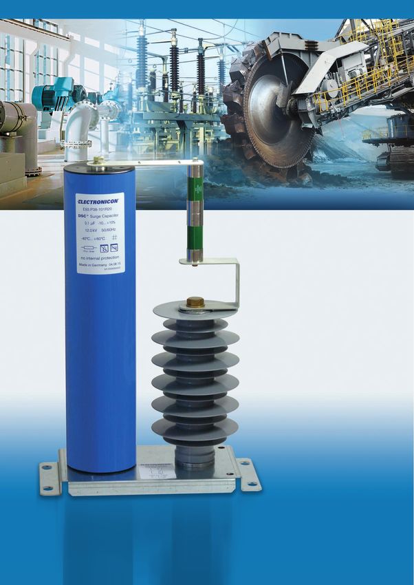
19DSCTM
Who said it has to look like a surge capacitor? Wer sagt, daß er wie ein Überspannungs-
schutzkondensator aussehen muß?
Keeping with its tradition of completely dry products, ELECTRONICON has In bester Tradition ihrer Kondensatoren in Trockentechnologie präsentiert
launched the first MV Surge Capacitor in self-healing technology. The DSC™ ELECTRONICON den ersten selbstheilenden Überspannungsschutzkon-
surge voltage protection capacitor („surge capacitor“) is the ideal solution densator für Mittelspannungsanwendungen. Der DSCTM ist die passende
for limiting transient overvoltages. In combination with the PD-free layout, Lösung zum Begrenzen transienter Überspannungen. Das selbstheilende
the self-healing dielectric provides for extremely long operating life and Dielektrikum sorgt in Verbindung mit einer teilentladungsfreien Dimen-
highest operational safety. Thanks to the solid polyurethane filling, the sionierung für eine extrem hohe Lebensdauer und Funktionssicherheit.
DSC™ can be installed in any mounting position. Moreover, there are no Dank seines trockenen Polyurethanvergusses kann der DSCTM in jeder
liquids to threaten the environment or to be considered during disposal at Einbaulage verwendet werden. Außerdem können keine grundwasserge-
the end of operational life. fährdenden Flüssigkeiten austreten, auch bei der Entsorgung am Ende der
Nutzungsdauer ist auf keine Flüssigkeiten Rücksicht zu nehmen. Durch
With their uncomplicated terminals and the plastic housing, our surge die unkomplizierten Anschlussterminals und die Verwendung eines Kunst-
capacitors do not only have a completely different optical appearance than stoffbechers unterscheiden sich unsere Kondensatoren auch optisch von
traditional oil-filled ALLFILM capacitors, but also offer substantial savings den herkömmlichen ölgefüllten Allfilm-Kondensatoren. Vergleichen Sie:
in weight, space and cost. Consider this: a DSC™ 0.25µF / 12kV weighs Ein 0,25µF / 12kV DSC™ Kondensator wiegt nur 4,1kg im Vergleich zu wuch-
4.1kg compared to a whopping 15kg of market-common capacitors. tigen 15kg eines marktüblichen Allfilm-ÜS-Kondensators.
Utility model registered and protected by German Patent and Trade Mark Die neuartige Lösung des DSCTM ist unter Nummer 20 2010 009 760.6 des
Office (DPMA) under file no. 20 2010 009 760.6. DPMA gebrauchsmustergeschützt.
Surge Capacitors - a useful add-on, saving Überspannungsschutzkondensatoren – ein
cost nützlicher Zusatz, der Kosten spart
Sooner or later in their operating life, medium voltage motors and trans- Mittelspannungsmotoren und -transformatoren werden während ihrer
formers are confronted with transient overvoltages. These glitches are Lebensdauer früher oder später mit transienten Überspannungen belastet.
caused either by simple switching operations in the medium-voltage mains, Verursacht werden diese Störimpulse entweder durch einfache Schalt-
or by atmospheric discharges. Such impulses are called “surge” and have a vorgänge in den Mittelspannungsnetzen oder durch atmosphärische Ent-
rise time of no more than a few microseconds, exceeding a multiple of the ladungen. Die als „surge“ bezeichneten Impulse besitzen Anstiegszeiten
rated mains voltage within that short period. The first winding turn of an von maximal wenigen Mikrosekunden und übersteigen in dieser kurzen
electrical machine is stressed very heavily by the very steep voltage rise. Zeit ein Vielfaches der Netznennspannung. Durch den sehr hohen Span-
This sole winding’s thin insulation is then the only protection from a voltage nungsgradienten wird die erste Windung einer elektrischen Maschine
breakdown and – hence – failure of the entire equipment. spannungsmäßig sehr stark belastet. Somit ist die dünne Isolation einer
INTRODUCTION_EINLEITUNG_DSCTM
einzigen Windung der einzige Schutz vor einem Durchschlag und damit vor
einem Ausfall des Betriebsmittels.
Surge capacitors are able to smoothen voltage surges provoked by switch- Überspannungsschutzkondensatoren sind in der Lage, einen durch Schalt-
ing operations. The – properly sized – capacitance absorbs the major part vorgänge verursachten Spannungsstoß zu dämpfen und seinen Anstieg zu
of the electrical charge when the overvoltage occurs, and discharges it verzögern. Die ausreichend hohe Kapazität des Kondensators nimmt beim
soon afterwards. Hereby the overvoltage is attenuated to ca. 10% of its Auftreten der Überspannung den größten Teil der elektrischen Ladung auf
maximum level. Simultaneously, this limits the rate of voltage rise, split- und gibt sie kurz darauf wieder ab. Durch diesen Vorgang wird die Höhe
ting the reduced overvoltage over substantially more winding turns than der Überspannung auf etwa 10% ihres Maximums bedämpft. Dies begrenzt
before; no winding insulation is overloaded by extreme overvoltages any- gleichzeitig den Spannungsgradienten, wodurch die reduzierte Überspan-
more. nung sich zusätzlich auf viel mehr Windungen verteilt. Somit wird keine
Windungsisolation mehr durch extreme Überspannungen belastet.
20DSCTM
Voltage shape
Spannungskurve
25000 V 25000 V
20000 V 20000 V
15000 V 15000 V
10000 V 10000 V
5000 V 5000 V
0V 0V
0 5 10 15 20 ms 5.00 5.02 5.04 5.06 5.08 5.10 ms
-5000 V -5000 V
Voltage shape with surge at an MV transformer. blue: line voltage with 0.25µF capacitor
Spannungskurve an einem MS-Transformator. blau: Netzspannung mit 0.25µF Kondensator
Surge capacitors are permanently connected to the mains and instantly Ein Überspannungsschutzkondensator ist fest im Netz verschaltet. Dadu-
available without any switching delays in the event of a fault situation. rch steht seine Funktion permanent zur Verfügung. Er muß im Fehlerfall
It is recommended to use additional overvoltage arresters for the damp- nicht erst zugeschaltet werden oder zünden, wodurch ein Zeitverzug ein-
ing of heavy current pulses of 100kA or more (as are typical for lightning treten würde. Zur Bedämpfung stromstarker Impulse von 100 kA und mehr,
discharges). wie sie etwa bei Blitzentladungen auftreten, empfiehlt sich der zusätzliche
Einsatz von Überspannungsableitern, i.d.R. an zentraler Stelle.
According to a study published on an IEEE-conference in 1995, the addi- Nach einer 1995 auf einer IEEE-Konferenz veröffentlichten Studie lohnen
tional cost and space spent on surge capacitors are well worth the extra sich die Mehrkosten für die Kondensatoren und den zusätzlichen Platz-
expense (approx. 15 - 20% of the motor cost): an alternative over-sizing bedarf in der Anlage. Der finanzielle Mehraufwand liegt bei 15 - 20% der
of the initial motor or transformer windings for enhanced strength against Motorkosten. Legt man alternativ die ersten Windungen eines Motors oder
transient over-voltages would require a bigger winding window which would eines Transformators für die Belastung durch transiente Überspannun-
imply a larger machine and a cost increase by approx. 35…50%. gen aus, benötigt der Motor ein größeres Wickelfenster. Dies macht die
Maschine größer und führt zu Mehrkosten von insgesamt 35 - 50%.
INTRODUCTION_EINLEITUNG_DSCTM
21DSCTM
3.3...17.5 kVrms for latest edition and updates
check www.powercapacitors.info
Dry surge capacitors
Trockene Überspannungsschutzkondensatoren
standard . . . . . . . . . . . . . . . . tested according to IEC 60871-1 permitted overvoltages
8h/d . . . . . . . . . . . . . . . . . . . . . . . . . . . . . . . . . . . .1.10 × UN
can . . . . . . . . . . . . . . . . . . . . . plastic (UL94:V0) 30min/d . . . . . . . . . . . . . . . . . . . . . . . . . . . . . . . . .1.15 × UN
dielectric material . . . . . . . . low-loss polypropylene, dry dielectric 5min/d . . . . . . . . . . . . . . . . . . . . . . . . . . . . . . . . . .1.20 × UN
filling material . . . . . . . . . . . solid, based on vegetable oil, non -PCB 1min/d . . . . . . . . . . . . . . . . . . . . . . . . . . . . . . . . . .1.30 × UN
humidity class . . . . . . . . . . . F
mounting position. . . . . . . . . optional test voltage between terminals . . . . . . . . . . . . . .2.15 × UN 50Hz (10s)
internal protection . . . . . . . . none
discharge resistor . . . . . . . . internal: < 75V in < 2 min insulation quality . . . . . . . . . . . . . . . . . . . . . . . . .25000s
fire load. . . . . . . . . . . . . . . . . 40MJ/kg dissipation losses (capacitor) . . . . . . . . . . . . . . . .0,2W / kvar
degree of protection . . . . . . . IP 00
clearance in air/ operating temperature . . . . . . . . . . . . . . . . . . . . .–40°C / +60°C
creepage distance . . . . . . . . D + L – 20 mm storing temperature . . . . . . . . . . . . . . . . . . . . . . .–40°C / +70°C
CN tolerance. . . . . . . . . . . . . . ±10%
statistical life expectancy . . . . . . . . . . . . . . . . . . .> 150 000h
UN CN IN IS US D×L m order no.
(kV) (µF) (A) (kA) (kV) (mm) (kg) Bestell-Nr.
3.3 0.1 0.1 0.6 14 64 × 165 0.6 E93.L16-101R20
3.6 0.25 0.28 1 14 90 × 165 1.1 E93.P16-251R20
3.6 0.5 0.57 1.7 14 90 × 285 1.9 E93.P28-501R20
6.6 0.1 0.21 1.3 26 90 × 285 1.9 E93.P28-101R20
DATA CHARTS_DATENTABELLEN_DSCTM 3.3...17.5kVrms
6.6 0.5 1.04 3.9 22 116 × 310 3.4 E93.P31-501R20
7.2 0.25 0.57 2.8 29 116 × 285 3.2 E93.R28-251R20
7.2 0.5 1.13 2 29 90 × 385 2.6 E93.P38-501R20
12 0.1 0.38 1.2 48 90 × 385 2.6 E93.P38-101R20
12 0.25 0.94 3.2 48 116 × 390 4.3 E93.R38-251R20
12 0.5 1.88 3.5 48 116 × 620 6.9 E93.R62-501R20
17.5 0.25 1.37 6.3 70 140 × 570 9.2 E93.S57-251R20
17.5 0.5 2.75 5 52 140 × 850 13.7 E93.S85-501R20
Dimension drawing
Maßbild
22Sie können auch lesen