PEC APPLICATION NOTES / ANWENDUNGSHINWEISE
←
→
Transkription von Seiteninhalten
Wenn Ihr Browser die Seite nicht korrekt rendert, bitte, lesen Sie den Inhalt der Seite unten
w w w. e l e c t r o n i c o n . c o m

                  PEC APPLICATION NOTES / ANWENDUNGSHINWEISE
CAPACITORS FOR APPLICATIONS
                IN POWER ELECTRONICS

                   always in charge
APPLICATION NOTES
AND SELECTION GUIDE
ANWENDUNGSHINWEISE UND BERECHNUNGSBEISPIELE

                                                  ISSUE_AUSGABE - 2013 -

                                              3
4
GENERAL REMARKS                                               6    ALLGEMEINER TEIL                                             6

  FIELDS OF APPLICATION                                        6     ANWENDUNGSBEREICH                                          6
  INTERNAL CONSTRUCTION                                        7     INNERER AUFBAU                                             7
  Dielectric – Impregnants                                           Dielektrikum – Füllstoffe
  SAFE OPERATION                                               8     BETRIEBSSICHERHEIT                                         8
  Self-Healing Dielectric – Protection Against Accidental            Selbstheilendes Dielektrikum – Berührungssicherheit –
  Contact – Protection against Overload                              Schutz gegen Überlastung
  DEFINITIONS AND SELECTION CRITERIA                          10     BEGRIFFE UND AUSWAHLKRITERIEN                             10

SELECTION GUIDE                                             21     BERECHNUNGSBEISPIELE                                        21

  INTRODUCTION                                                22     EINFÜHRUNG                                                22
  Capacitor for an AC application                             23     Kondensatoren für Wechselspannungsanwendungen             23
  Capacitor for a DC application                              27     Kondensatoren für Gleichspannungsanwendungen              27
  AC Filter capacitor                                         30     Kondensatoren für Wechselspannungsfilter                   30

ANNEX                                                       35     ANHANG                                                      35

  MOUNTING AND OPERATING INSTRUCTIONS                         36     VORSCHRIFTEN ZU EINBAU UND BETRIEB                        36
  Mounting Position – Mounting Location/Cooling – Vibration          Einbaulage – Einbauort/Kühlung – Schwingungs-
  Stress – Connection – Fixing Torque – Discharge – Earthing –       belastung – Anschluss – Anzugs-Drehmomente –
  Environmental compatibility – Disposal                             Entladung – Erdung – Umweltverträglichkeit – Entsorgung

ZVEI-SAFETY DATA SHEET                                      40     ZVEI- SICHERHEITSHINWEISE                                   42

CERTIFICATES                                                44     ZERTIFIKATE                                                 44

PACKING DETAILS                                             45     VERPACKUNGSDATEN                                            45

CONVERSION CHARTS                                           46     UMRECHNUNGSTABELLEN                                         46

                                                                                                                                        TABLE OF CONTENTS_INHALT

                                                                                                                                    5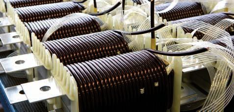
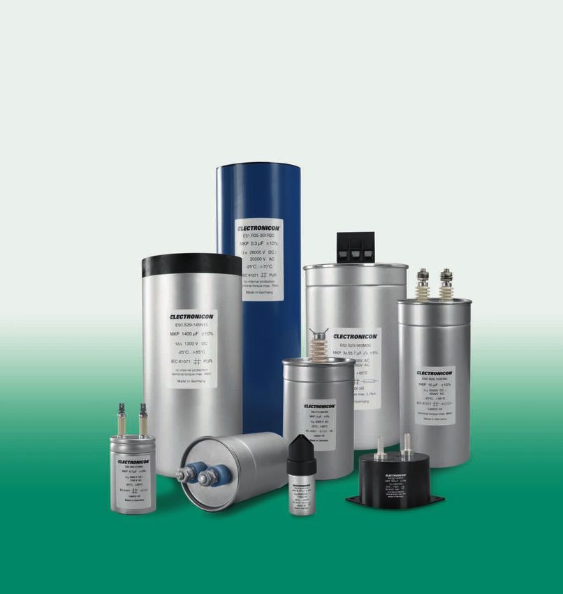
FIELDS OF APPLICATION
                                          ANWENDUNGSBEREICH

                                                                      Capacitors for power electronics can be used for a wide variety of applica-       Kondensatoren für die Leistungselektronik sind universell einsetzbare
                                                                      tions, even where extremely non-sinusoidal voltages and pulsed currents are       Kondensatoren, die auch mit stark von der Sinusform abweichenden Span-
                                                                      present. Both AC and DC capacitors are available. AC capacitors are periodi-      nungen und mit impulsförmigen Strömen betrieben werden können. Man
                                                                      cally recharged during operation, DC capacitors are periodically charged and      unterscheidet Wechselspannungs- und Gleichspannungskondensatoren.
                                                                      discharged without recharge.                                                      Wechselspannungskondensatoren werden im Betrieb periodisch umgeladen,
                                                                                                                                                        Gleichspannungskondensatoren werden periodisch aufgeladen und entladen,
                                                                                                                                                        wobei keine Umladung erfolgt.

                                                                      AC CAPACITORS serve as damping or snubber capacitors connected in se-             WECHSELSPANNUNGSKONDENSATOREN dienen unter anderem als Be-
                                                                      ries with a resistor, and are designed for the damping of undesirable voltage     dämpfungskondensatoren, in Reihe mit einem ohmschen Widerstand,
                                                see Selection Guide   spikes caused by the so-called carrier storage effect during the switching        zur Dämpfung von Spannungsspitzen, die beim Abschalten von Leistungs-
                                                             pg. 23
                                               Berechnungsbeispiel
                                                                      of power semiconductors. When applied as commutation capacitors, they             halbleitern durch den sogenannten Trägerstaueffekt entstehen. In der
                                                              S. 23   are switched in parallel to a thyristor and designed to quench its conductive     Anwendung als Kommutierungskondensatoren werden sie zum Löschen
                                                                      state. Since commutating capacitors are periodically and abruptly recharged,      des leitenden Zustandes eines Thyristors benutzt, indem sie durch Parallel-
                                                                      the peak current will substantially exceed the rms value.                         schalten zum Thyristor den Strom kurzzeitig übernehmen. Bei der perio-
                                                                                                                                                        dischen stoßartigen Umladung können die Stromscheitelwerte dabei
                                                                                                                                                        wesentlich höher als die Effektivwerte sein.
                                                see Selection Guide   Further, AC capacitors are used in low-detuned or close-tuned filter circuits      Desweiteren finden Wechselspannungskondensatoren Anwendung in ab-
                                                             pg. 30
                                               Berechnungsbeispiel    for filtering or absorbing harmonics. As pulse discharge capacitors, they         gestimmten oder verstimmten Filterkreisen zur Filterung oder gezielten Ab-
                                                              S. 30
                                                                      are useful in applications with reversing voltages, e.g. in magnetizing equip-    saugung von Oberwellen. Als Stoßentladekondensatoren werden sie in An-
                                                                      ment.                                                                             wendungen mit durchschwingender Spannungskurve eingesetzt, z.B. in
                                                                                                                                                        Magnetisierungsanlagen.

                                                                      Series E62, E62-3ph, E93, E12, E33 have been designed for AC use. Further,        Für Wechselspannungsanwendungen sind v.a. die Reihen E62, E62-3ph,
                                                                      specially adapted capacitors from the E51, E53, E56 and E59 ranges are avail-     E93, E12, E33 ausgelegt. Speziell angepasste Ausführungen in den Reihen
                                                                      able for AC applications on request.                                              E51, E53, E56 und E59 sind auf Anfrage ebenfalls erhältlich.

                                                                      The scope of application for DC CAPACITORS is similarly diverse:                  Der Anwendungsbereich für GLEICHSPANNUNGSKONDENSATOREN ist eb-
                                                                      Smoothing capacitors serve for the reduction of the AC component of               enso weit gefächert: Als Glättungskondensatoren dienen sie der Verrin-
                                                see Selection Guide   fluctuating DC voltage, e.g., in power supplies in radio and television           gerung des Wechselspannungsanteils pulsierender Gleichspannung, zum
FIELDS OF APPLICATION_ANWENDUNGSBEREICH

                                                             pg. 27   technology (transmitters,) high-voltage testing equipment, DC control-            Beispiel in Stromversorgungen der Rundfunk- und Fernsehtechnik (Sender),
                                               Berechnungsbeispiel
                                                              S. 27   lers, measurement and control technology, cascaded circuits for gen-              Hochspannungs-Prüfgeräten, Gleichspannungsreglern, in der Mess- und
                                                                      eration of high DC voltage a.m.o. Supporting capacitors, DC-Filter or DC          Regeltechnik, in Kaskadenschaltungen zur Erzeugung hoher Gleich-
                                                                      Link capacitors are used for energy storage in intermediate DC circuits,          spannung, u.v.a. Stütz-, Gleichspannungsfilter- oder Zwischenkreiskon-
                                                                      e.g. in frequency converters for poly-phase drives, transistor and thyris-        densatoren werden eingesetzt als Energiespeicher in Gleichspannungs-
                                                                      tor converters. They must be able to absorb and release very high currents        zwischenkreisen, z.B. in Frequenzumrichtern von Drehstromantrieben,
                                                                      within short periods, the peak value of the current being substantially greater   Transistor- und Thyristorumrichtern. Dabei müssen sie kurzzeitig sehr hohe
                                                                      than the rms value.                                                               Ströme abgeben und aufnehmen können.

                                                                      Surge (Pulse) discharge capacitors are also capable of supplying or               Auch Stoßentladekondensatoren sind in der Lage, kurzzeitig starke
                                                                      absorbing extreme short-time current surges. They are usually operated in         Stoßströme abzugeben; sie werden vor allem bei Entladevorgängen mit nicht
                                                                      discharge applications with non-reversing voltages, and at low repetition         durchschwingendem Spannungsverlauf eingesetzt, und meist mit niedrigen
                                                                      frequencies, e.g. in laser technology and lightning generators.                   Folgefrequenzen betrieben, z.B in der Lasertechnik und in Blitzgeneratoren.

                                                                      Series E63, E50, E51, E56, E59, E61 but also E62, E65, E53 and E57 can be         Die Typenreihen E63, E50, E51, E56, E59, E61 sowie E62, E65, E53 und E57
                                                                      used for DC applications.                                                         sind für den Einsatz in Gleichspannungsanwendungen geeignet.

                                          6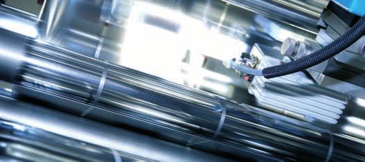
winding element Wickelkörper

    margin, uncoated
    Randstreifen unmetallisiert                                                                                                                       INTERNAL CONSTRUCTION
                                                                                                                                                             INNERER AUFBAU

                                                   contact layer Stirnkontaktschicht

                                             polypropylene film, metal deposit on one side
                                                Polypropylenfolie, einseitig metallisiert

Dielectric                                                                                   Dielektrikum

MKP-type capacitors are based on a low-loss dielectric formed by pure poly-                  Kondensatoren in MKP-Technologie basieren auf einem verlustarmen Dielek-
propylene film. A thin self-healing mixture of zinc and aluminium is met-                    trikum aus reiner Polypropylenfolie. Eine dünne, selbstheilende Mischung
allized directly on one side of the PP-film under vacuum. In some cases,                     aus Zink und Aluminium wird unter Vakuum direkt auf eine Seite der Polypro-
additional unmetallized layers are added between the metallized ones.                        pylenfolie aufgedampft. Bei zweilagigem Aufbau werden zwischen den metal-
                                                                                             lisierten Bahnen zusätzlich unmetallisierte Bahnen angeordnet.

The plastic film is wound into stable cylindrical windings on the most modern                Die auf modernsten Maschinen hergestellten einphasigen Wickel werden an
automated equipment. The ends of the capacitor windings are contacted by                     beiden Enden durch Aufsprühen einer Metallschicht kontaktiert. Hierdurch
spraying with a metal contact layer, facilitating a high current load and en-                wird eine hohe Strombelastbarkeit sowie eine niederinduktive Verbindung
suring a low-inductance connection between the terminals and windings.                       zwischen den Anschlüssen und den Wickeln garantiert.

Our long-term experience as well as on-going research and improvements                       Unsere langjährigen Erfahrungen, ständige Forschungen und eine stetige
in this technology ensure the excellent self-healing characteristics of the                  Weiterentwicklung dieser Technologie sind Grundlage für die lange Betriebs-
dielectric and a long operating life of our capacitors.                                      dauer und die guten Selbstheileigenschaften unserer Kondensatoren.

The link between PP-film and zinc contact layer is highly stressed during high               Die Verbindung zwischen Folie und Stirnkontaktschicht wird bei hohen Stoß-
surge or rms currents and therefore considered very critical for operating life              und Effektivströmen außerordentlich hoch belastet und gilt als besonders
and reliability of the capacitor. By cutting the film in a wavelike manner, our              kritisch für Lebensdauer und Funktionssicherheit des Kondensators. Diese
                                                                                                                                                                           SINECUT™
well-proven SineCut™- technology increases the contact surface between                       relative Belastung reduzieren wir durch unser bewährtes SineCut™-Verfah-
film and zinc layer and reduces this strain substantially.                                   ren, indem wir durch wellenförmiges Schneiden der Folienbahnen die Aufla-
                                                                                             gefläche der Stirnkontaktschicht deutlich vergrößern.

Impregnants                                                                                  Füllstoffe

The use of filling materials in capacitors is necessary in order to insulate                 Die Verwendung von Füllstoffen ist unerlässlich, um die Elektroden des Kon-
the capacitor electrodes from oxygen, humidity, and other environmental                      densators vor Sauerstoff, Feuchtigkeit und anderen Umwelteinflüssen ab-
interference. Without such insulation, the metal coating would corrode, an                   zuschirmen. Ohne eine solche Isolation würden die Metallbeläge korrodieren
increasing number of partial discharges would occur, the capacitor would                     und die Anzahl von Teilentladungen würde zunehmen. Ständige Kapazitäts-
lose more and more of its capacitance, and suffer increased dielectric losses                verluste, steigende dielektrische Verluste und eine verkürzte Lebensdauer

                                                                                                                                                                                          INTERNAL CONSTRUCTION_INNERER AUFBAU
and a reduced operating life.                                                                wären die Folge.

Therefore, an elaborate vacuum-drying procedure is initiated immediately                     Nach dem Einbau der Wickel in das Kondensatorgehäuse und sorgfältiger
                                                                                                                                                                               BIO
after insertion of the winding elements into the capacitor case and biologically             Vakuumtrocknung wird dieses daher mit biologisch abbaubarem Pflanzenöl
degradable plant oil, solid PUR resin or inert insulation gas are introduced.                bzw. aushärtendem Polyurethanharz oder mit neutralem Isoliergas aufgefüllt.
That protects the winding from environmental influence and provides an                       Das schützt den Wickel vor Umwelteinflüssen und verhilft dem Kondensator
extended life-expectancy and stable capacitance.                                             zu einer langen Lebensdauer und stabiler Kapazität.

                                                                                                                                                                                      7
SAFE OPERATION
                                    BETRIEBSSICHERHEIT

                                                Protection Against Overvoltages and                                                 Schutz gegen Überspannungen und
                                                Short Circuits: Self-Healing Dielectric                                             Kurzschlüsse: Selbstheilendes Dielektrikum

                                                All dielectric structures used in our capacitors are ”self-healing”: In the         Alle in unseren Kondensatoren eingesetzten dielektrischen Strukturen
                                                event of a voltage breakdown the metal layers around the breakdown channel          sind selbstheilend. Im Falle eines Kurzschlusses (Spannungsdurchschlag)
                                                are evaporated by the temperature of the electric arc that forms between the        verdampfen die Metallbeläge um den Durchschlagspunkt herum aufgrund
                                                electrodes. They are removed within a few microseconds and pushed apart by          der Temperatur des Lichtbogens, der sich zwischen den Elektroden bildet.
                                                the pressure generated in the centre of the breakdown spot.                         Innerhalb weniger Mikrosekunden wird der Metalldampf durch den beim
                                                An insulation area is formed which is reliably resistive and voltage proof          Durchschlag entstehenden Überdruck vom Zentrum des Durchschlages
                                                for all operating requirements of the capacitor. The capacitor remains fully        weggedrückt. Auf diese Weise bildet sich eine belagfreie Zone rings um den
                                                functional during and after the breakdown.                                          Durchschlagspunkt, wodurch dieser vollständig isoliert wird. Der Kondensator
                                                                                                                                    bleibt während und nach dem Durchschlag voll funktionsfähig.

                                                  Self-healing breakdown
                                                  Selbst heilender Durchschlag

                                                Protection Against Accidental Contact                                               Berührungssicherheit

                                                All capacitors are checked by routine test: voltage test between shorted            Alle Kondensatoren werden 100%ig der Isolationsprüfung zwischen kurzge-
                                                terminations and case in accordance with IEC 61071. Accessible capacitors           schlossenen Anschlüssen und Gehäuse mit einer Prüfspannung unterzo-
                                                must be earthed at the bottom stud or with an additional earthing clamp.            gen, welche mindestens den Werten nach IEC 61071 entspricht. Trotzdem
                                                                                                                                    sind zugängliche Kondensatoren mittels des Bodenbolzens oder einer
                                                                                                                                    Metallschelle zu erden.
                                                The                       terminal block of designs K, L and M (1/3) is rated       Das                     Anschlusselement der Bauformen K, L und M (1/3)
                                                IP20, i.e. it is protected against accidental finger contact with live parts. All   weist einen Schutzgrad IP20 auf, d.h. es ist vor Berührung mit dem Finger
                                                other capacitors are not protected against accidental contact.                      geschützt, so dass spannungsführende Teile nicht berührt werden können.
                                                                                                                                    Alle anderen Anschlussarten sind nicht berührungsgeschützt.

                                                Protection Against Overvoltages                                                     Sicherheit bei Überspannungen
SAFE OPERATION_BETRIEBSSICHERHEIT

                                                and External Short Circuits                                                         und äußeren Kurzschlüssen

                                                As shown above, the capacitors are self-healing and regenerate themselves           Die Kondensatoren sind aufgrund des oben beschriebenen Aufbaus über-
                                                after breakdowns of the dielectric. For voltages within the permitted testing       spannungsfest, da sich die Kondensatoren nach einem Durchschlag im
                                                and operating maximum the capacitors are overvoltage-proof. They are also           Dielektrikum selbst regenerieren, sofern die zulässigen Prüf- und Betriebs-
                                                proof against external short circuits as far as the resulting surge discharges      spannungen nicht überschritten werden. Sie sind außerdem sicher gegen
                                                do not exceed the specified current limits (IS).                                    äußere Kurzschlüsse, sofern bei den dabei entstehenden Stoßentladungen
                                                                                                                                    die zugelassenen Grenzströme (IS) nicht überschritten werden.

                                                 1.1 × UN               30% of the service period der Betriebszeit
                                                 1.15 × UN              30 min/d
                                                 1.2 × UN                5 min/d
                                                                                                                                    IEC 61071
                                                 1.3 × UN                1 min/d
                                                                                                                                    Permitted Overvoltages
                                                 1.5 × UN              100 ms no more than 1000 times max. 1000 mal                 Zulässige Überspannungen

                                    8
Protection Against Overload and Failure                                           Schutz gegen Überlastung und
at the End of Useful Service Life                                                 Fehlfunktionen am Ende der Lebensdauer

In the event of overvoltage or thermal overload or ageing at the end of           Bei spannungsmäßiger oder thermischer Überlastung bzw. am Ende der
the capacitor’s useful service life, an increasing number of self-healing         Lebensdauer kann durch zahlreiche Selbstheildurchschläge und Zersetzung
breakdowns may cause disintegration of the dielectric film and rising pressure    des Dielektrikums ein Überdruck im Kondensator entstehen. Um ein Bersten
inside the capacitor. To prevent it from bursting, the capacitors of series       der Gehäuse zu verhindern, sind die Kondensatoren der Baureihen E62, E63
E62, E63 and E65 are fitted with an obligatory «break action mechanism»           und E65 generell mit einer Überdruck-Abreißsicherung (BAM) versehen. Diese
(BAM). This safety mechanism is based on an attenuated spot at one of the         Sicherung besteht aus einer Sollbruchstelle in einem der Anschlussdrähte.
connecting wires inside the capacitor. With rising pressure the case begins to    Bei einem Überdruck im Kondensator verlängert sich das Gehäuse durch
expand, mainly by opening the folded crimp and pushing the lid upwards. As a      das Öffnen der gestauchten Sicke bzw. Wölbung des Metalldeckels und
result, the prepared connecting wire is separated at the attenuated spot, and     die Stromzufuhr zu den Kondensatorwickeln wird an der Sollbruchstelle
the current path is interrupted irreversibly.                                     irreversibel unterbrochen.
It has to be noted that this safety system can act properly only within the       Es ist zu beachten, dass dieses Sicherungsprinzip nur innerhalb der zulässigen
permitted limits of loads and overloads.                                          Be- und Überlastungsgrenzen zuverlässig wirken kann.

   Principle of the break action mechanism (BAM)
   Prinzip der Überdruck-Abreißsicherung (BAM)

                                                                        Break action spot
                                                                         Sollbruchstelle

                                                                                                                                                                       SAFE OPERATION_BETRIEBSSICHERHEIT

! MIND HAZARDS OF EXPLOSION AND FIRE                                              ! BERSTRISIKO UND BRANDLAST BEACHTEN

   Capacitors consist mainly of polypropylene (up to 90%), i.e. their                Kondensatoren bestehen zu bis zu 90% aus Polypropylen, d.h. ihre
   energy content is relatively high. They may rupture and ignite as                 Brandlast ist relativ hoch. Infolge von internen Fehlern oder externen
   a result of internal faults or external overload (e.g. temperature,               Faktoren (z.B. Temperatur, Überspannung, Oberschwingungen) können
   overvoltage, harmonic distortion). It must therefore be ensured,                  sie platzen und sich entzünden. Deshalb ist durch geeignete Maßnahmen
   by appropriate measures, that they do not form any hazard to their                dafür zu sorgen, dass sie im Fehlerfall bzw. bei einem Versagen der
   environment in the event of failure or malfunction of the safety                  Sicherungsmechanismen kein Risiko für ihre Umgebung darstellen.
   mechanism.

   FIRE LOAD: approx. 40 MJ/kg                                                       BRANDLAST: ca. 40MJ/kg

   EXTINGUISH WITH: solid extinguishing agent, CO2, foam                             LÖSCHMITTEL: Trockenlöschmittel, CO2, Schaum

                                                                                                                                                                   9
DEFINITIONS AND SELECTION CRITERIA
                       BEGRIFFE UND AUSWAHLKRITERIEN

                                     The terms and abbreviations used in this brochure are based mainly              Die in diesem Heft verwendeten Begriffe und Abkürzungen orientieren
                                     on the actual standard for power electronics capacitors, IEC 61071,             sich weitestgehend an der gültigen Norm für Leistungselektronik-
                                     however, minor deviations may occur.                                            Kondensatoren, IEC 61071. Geringfügige Abweichungen sind jedoch
                                                                                                                     möglich.

                                     Rated capacitance CN                                                            Bemessungskapazität (Nennkapazität) CN
                                     Capacitance value rated at 20°C / 50 Hz.                                        Nennwert der Kapazität, bezogen auf 20°C, 50 Hz.
                              CN
                                     Rated Voltage UN
                                     The maximum or peak voltage of either polarity of a reversing or nonreversing                     U (t)
                                     type wave form for which the capacitor has been designed and rated (unlike
                                     other standards for AC capacitors, the rated voltage is not the rms value).

                                                                                                                       US
                                     Bemessungsspannung (Nennspannung) UN
                                                                                                                                UN
                                     Größtwert bzw. Scheitelwert der Spannung, für die der Kondensator dimen-
                                     sioniert und benannt ist (abweichend von anderen Normen für Wechselspan-                                                                                    t
                                     nungskondensatoren nicht der Effektivwert!)

                                     Non recurrent surge voltage US                                                  Stoßspitzenspannung US
                                     Voltages beyond the rated voltage induced by switching or faults of the         Höchster Spitzenwert, der vereinzelt kurzzeitig im Störungsfall auftreten darf.
                                     system or any part of it. Maximum count 1000 times with a duration of not       Maximale Anzahl 1000 mal mit einer Höchstdauer von jeweils 100 ms.
                                S    more than 100 ms each.

                                     rms voltage Urms                                                                Effektive Wechselspannung Urms
                                     Root mean square of max. permissible value of sinusoidal AC voltage in          Maximal zulässiger Effektivwert von sinusförmiger Wechselspannung im
                                     continuous operation. In power electronics, the RMS voltage is usually not      Dauerbetrieb. In der Leistungselektronik ist der Effektivwert in der Regel
                               rms
                                     the rated voltage value of the capacitor.                                       nicht der Nennwert des Kondensators.

                                     Ripple voltage Ur                                                               Überlagerte Wechselspannung Ur
                                     Maximum value of the peak-to-peak alternating component of the uni-direc-       Maximalwert des dauernd zulässigen Spitze-Spitze-Wertes der einer DC-
                                     tional voltage. This value is stated only for DC-capacitors. The peak-to-peak   Spannung überlagerten Wechselspannung. Dieser Wert wird nur bei DC-
                                r    value of AC- and AC/DC-types is always 2 × UNAC.                                Kondensatoren angegeben. Bei AC und AC/DC –Typen beträgt der zulässige
                                                                                                                     Spitze-Spitze-Wert 2 × UNAC.

                                                                                                                                                  Ripple Voltage Ur
                                             U                                                                                                    Überlagerte Wechselspannung
DEFINITIONS_BEGRIFFE

                                                                                                             Rated voltage UN
                                                                                                             Nennspannung

                                                                   DC voltage
                                                                   Gleichspannung

                                                                                                                                                                                          t

                       10
Voltage test between terminals UBB Prüfspannung Belag/Belag UBB
Routine test of all capacitors conducted at room temperature, prior to deli- Prüfspannung, mit der alle Kondensatoren als Stückprüfung zwischen den
very. A further test with 80% of the test voltage stated in the data sheet may Anschlüssen vor der Auslieferung geprüft werden. Beim Anwender ist eine
be carried out once at the user’s location. Wiederholung dieser Prüfung mit dem 0,8fachen Wert der Prüfspannung
zulässig.
Voltage test between terminals and case UBG Prüfspannung Belag/Gehäuse UBG
Routine test of all capacitors between short-circuited terminals and case, Prüfspannung, mit der alle Kondensatoren zwischen den kurzgeschlossenen
conducted at room temperature. May be repeated at the user’s location. Anschlüssen und dem Gehäuse als Stückprüfung vor der Auslieferung geprüft
werden. Beim Anwender ist eine Wiederholung dieser Prüfung zulässig.
Insulation voltage Ui Isolationsspannung Ui
rms value of the AC voltage for which the terminals to case insulation has Effektivwert der Wechselspannung, nach der die Isolation zwischen den An-
been designed and tested. Based on the test voltage UBG stated in the cata- schlüssen und dem Gehäuse bemessen und geprüft ist. Aus der im Katalog Ui
logue, Ui can be calculated as follows: angegebenen Prüfspannung UBG lässt sich der Wert Ui wie folgt berechnen:
UBG – 1000V
Ui =
2
Rate of voltage rise (du/dt)max Flankensteilheit der Spannung (du/dt)max
Maximum permitted repetitive rate of voltage rise of the operational voltage. Periodisch zulässiger Maximalwert der Flankensteilheit der Betriebsspannung.
Es gilt der Zusammenhang:
(dudt) max
Î = CN x (du/dt)max
Maximum non-repetitive rate of voltage rise Stoß-Flankensteilheit (du/dt)S
(du/dt)S Höchster Spitzenwert der Flankensteilheit der Spannung, der vereinzelt im
Peak rate of voltage rise that may occur non-repetitively and briefly in the
event of a fault.
Störungsfall auftreten darf. Es gilt der Zusammenhang:
(dudt) s
IS = CN x (du/dt)s IS = non-repetitive peak current Stoßspitzenstrom
DEFINITIONS_BEGRIFFE
Maximum current Imax Maximalstrom Imax
Maximum rms value of permissible current in continuous operation. The va- Maximaler Effektivwert des im Dauerbetrieb zulässigen Stromes. Die im
lues given in the data sheets are related to either the specified maximum Datenblatt angegebenen Werte ergeben sich entweder aus der maximal
power dissipation or the current limits of the connection terminals. zulässigen Verlustleistung oder der Stromtragfähigkeit der Anschlüsse.
Peak current Î Spitzenstrom Î
Maximum permitted repetitive current amplitude during continuous operation. Periodisch zulässiger Scheitelwert des Stromes.
Î
11Non-repetitive peak current (surge) IS Stoßspitzenstrom IS
Maximum current that may occur non-repetitively and briefly in the event Höchster Spitzenwert, der vereinzelt kurzzeitig im Störungsfall auftreten darf.
of a fault. Maximum count 1000 times with a duration of not more than Maximale Anzahl 1000 mal mit einer Höchstdauer von jeweils 50 ms.
50 ms each.
Series resistance RS Serienwiderstand RS
Equivalent resistance representing the sum of the Ohmic resistances Ersatzwiderstand, welcher die Summe der im Kondensator auftretenden
RS occurring inside the capacitor. Essential for calculation of the current Ohmschen Widerstände repräsentiert. Maßgebend für die Berechnung der
dependent losses. Stromwärmeverluste.
PVR = I2eff x Rs PVR = current dependent losses Stromwärmeverluste
Equivalent Series Resistance RESR Serienersatzwiderstand RESR
Represents the sum of all loss resistances occurring in the capacitor (incl. Repräsentiert die Summe aller im Kondensator auftretenden Verlustwider-
RESR ohmic resistance RS). It depends on frequency and is essential for the calcu- stände (einschließlich Ohmsche Widerstände RS). Er ist frequenzabhängig und
lation of the capacitor’s total power losses PV . maßgebend für die Berechnung der Gesamtverluste des Kondensators PV .
tanδ0
RESR = RS +
2 πƒ x CN
PV = capacitor’s total power losses Geamtverluste des Kondensators
PV = I rms x RESR
2
Self-inductance Le Eigeninduktivität Le
Represents the sum of all inductive elements which are – for mechanical and Repräsentiert die Summe aller induktiven Bestandteile, die konstruktions-
Le construction reasons – contained in any capacitor. bedingt in jedem Kondensator enthalten sind.
Resonant frequency fres Resonanzfrequenz fres
The capacitance and self-inductance of any capacitor form a series resonant Kapazität und Eigeninduktivität eines jeden Kondensators bilden de facto einen
fres circuit. Above the resonant frequency, the inductive part of this LC-circuit Reihenresonanzkreis. Oberhalb der Resonanzfrequenz überwiegt in diesem LC-
prevails. The capacitor would then behave as an inductor. Kreis der induktive Anteil, der Kondensator wirkt dann nicht mehr als Kapazität.
fres = 1
2 π √Le x CN
DEFINITIONS_BEGRIFFE
Rated energy contents WN Nennenergiegehalt WN
Energy stored in the capacitor when charged at rated voltage. Bei Nennspannung im geladenen Kondensator gespeicherte Energie.
WN
CN
WN = × U²N
2
12Humidity classes Feuchteklassen
%RH
Class C Klasse C
°C
ambient temperature Umgebungstemperatur max. relative humidity
60
95% annual means
50 100% occasional
40
condensation permitted
35
33 30
max. relative Luftfeuchte
25 95% Jahresdurchschnitt,
100% gelegentlich
10
%RH
Betauung zulässig
0 10 20 30 40 50 60 70 80 90 100 %
humidity Luftfeuchte 95
Class F Klasse F
°C
ambient temperature Umgebungstemperatur max. relative humidity
60
75% annual means
50 95% 30 days/year
40
condensation not permitted
25
30
max. relative Luftfeuchte
23 75% Jahresdurchschnitt
21
95% 30 Tage/Jahr
10
%RH
Betauung nicht zulässig
0 10 20 30 40 50 60 70 80 90 100 %
humidity Luftfeuchte 75 85 95
Class G Klasse G
°C
ambient temperature Umgebungstemperatur
60
max. relative humidity
65% annual means
50
75% occasional
DEFINITIONS_BEGRIFFE
40 85% 60 days/year
condensation not permitted
27 30
25
24 max. relative Luftfeuchte
65% Jahresdurchschnitt,
10
%RH 75% gelegentlich
0 10 20 30 40 50 60 70 80 90 100 % 85% 60 Tage/Jahr
humidity Luftfeuchte 65 75 85 Betauung nicht zulässig
13Clearance in air L Luftstrecke L
The shortest distance between conducting parts of the terminals or between Kürzeste Strecke zwischen leitenden Teilen der Anschlüsse bzw. zwischen
L terminals and case. In this catalogue, we state only the shorter. Anschlüssen und Gehäuse. In diesem Katalog wird stets die kürzere von
beiden angegeben.
Creepage distance K Kriechstrecke K
The shortest distance along an insulated surface between conducting parts Kürzeste Strecke entlang der Isolierung zwischen leitenden Teilen der
K of the terminals or between terminals and case. In this catalogue, again we
state only the shorter.
Anschlüsse bzw. zwischen Anschlüssen und Gehäuse. In diesem Katalog wird
stets die kürzere von beiden angegeben.
Dielectric dissipation factor tanδ0 Dielektrischer Verlustfaktor tanδ0
Constant dissipation factor of the dielectric material for all capacitors at Konstanter Verlustfaktor des Dielektrikums für alle Kondensatoren bei Nenn-
tanδ0 their rated frequency. frequenz.
The typical loss factor of pp film is tanδ0 = 2 x 10⁻⁴. Der typische Verlustfaktor von Polypropylenfolie beträgt tanδ0 = 2 x 10⁻⁴.
Loss factor of the capacitor tanδ Verlustfaktor des Kondensators tanδ
Loss factor of the capacitor at sinusoidal ac voltage and applied frequency. Verlustfaktor des Kondensators bei sinusförmiger Wechselspannung und
tanδ It is calculated as follows: Einsatzfrequenz. Er errechnet sich wie folgt:
tanδ (ƒ) = tanδ0 + RS x 2πƒ x CN f = operating frequency Einsatzfrequenz
Thermal resistance Rth Thermischer Widerstand Rth
The thermal resistance indicates by how many degrees the capacitor Der Thermische Widerstand gibt an, um wieviel Grad sich der Kondensator
Rth temperature at the hotspot rises above the ambient temperature per Watt im Hotspot gegenüber der Umgebungstemperatur je Watt Verlustleistung
of the heat dissipation losses. It depends on a variety of factors. Hence the erwärmt. Der Wert gilt für ruhende Luft / Selbstkühlung. Der thermische
values shown in our data sheets refer to one single operating point only which Widerstand hängt von einer Vielzahl verschiedener Faktoren ab. Daher
is valid for still air/natural convection cooling. With forced cooling, Rth is stellt der Wert in den Datentabellen nur einen Arbeitspunkt dar, welcher für
reduced. Mind that the maximum Hotspot-temperature must not be exceeded ruhende Luft/Selbstkühlung gilt. Bei aktiver Luftkühlung wird der thermische
even with active cooling. Depending on the size of the capacitor, it takes Widerstand kleiner. Die Einhaltung der maximalen Hotspot-Temperatur ist
between a few minutes and several hours until this temperature balance is jedoch auch bei aktiver Kühlung stets zu gewährleisten. Je nach Größe des
DEFINITIONS_BEGRIFFE
finally reached. We recommend a test set-up with PT100 thermal elements Kondensators dauert es Minuten bis mehrere Stunden, bis der Kondensator
for exact values, or to contact ELECTRONICON’s staff for detailed support. diese Endtemperatur erreicht hat. Zur Ermittlung exakter Werte empfehlen
wir einen Versuchsaufbau mit PT100-Thermoelementen oder die Kontaktauf-
nahme mit ELECTRONICON.
14Ambient temperature ΘU Umgebungstemperatur ΘU
Temperature of the surrounding air, measured 10 cm away and at 2/3 of the Temperatur der umgebenden Luft, gemessen in ca. 10 cm Abstand vom
case height of the capacitor. Kondensator in etwa 2/3 der Gehäusehöhe. ΘU
Lower category temperature Θmin Untere Grenztemperatur Θmin
Lowest permissible ambient temperature at which a capacitor may be used. Niedrigste Umgebungstemperatur, bei der der Kondensator in Betrieb ge-
nommen werden darf. Θmin
Upper category temperature Θmax Obere Grenztemperatur Θmax
Highest permissible temperature during continuous operation, i.e. tempera- Höchste zulässige Temperatur an der heißesten Stelle der Kondensator-
ture at the hottest point of the capacitor case. It is, however, not sufficient oberfläche, bei der der Kondensator dauerhaft betrieben werden darf. Es Θmax
to monitor the surface temperature. Life-span and safe operation crucially ist jedoch nicht ausreichend, die Oberflächentemperatur zu kontrollieren.
depend on the observance of the hotspot temperature. Entscheidend für Lebensdauer und sicheren Betrieb ist die Einhaltung der
Hotspot-Temperatur.
Hotspot temperature ΘHOTSPOT Hotspot-Temperatur ΘHOTSPOT
Temperature at the hottest spot inside the capacitor. It has to be noted that, Temperatur der heißesten Stelle im Kondensatorinneren. Es ist zu beachten,
depending on the thermal power dissipation generated inside the capacitor, dass in Abhängigkeit der im Kondensatorinneren generierten Verlustleis- ΘHOTSPOT
there is always a temperature difference between hotspot and surface. As the tung stets ein Gefälle zwischen Hotspot und der Oberfläche besteht. Da die
hotspot is usually not accessible for measurement, ΘHOTSPOT must be calcu- Hotspot-Temperatur der Messung nicht zugänglich ist, muss die Ermittlung
lated based on the data stated in the catalogue or data sheet: rechnerisch mit Hilfe der Angaben im Datenblatt/Katalog erfolgen. Es gilt:
PV: thermal power dissipation Verlustleistung
ΘHOTSPOT = ΘU + PV × Rth
Q: reactive power of the capacitor Blindleistung des Kondensators
Irms: rms value of operating current Effektivwert des Betriebsstroms
PV = I2rms × RS + Q × tanδO
RS , tanδO: acc. to data sheet/catalogue nach Datenblatt/Katalog
Important: No thermal dissipation losses are admissible when operating a Es ist zu beachten: Wenn der Kondensator bei einer Umgebungstemperatur
capacitor at an ambient temperature equal to the upper category tempera- gleich der oberen Grenztemperatur betrieben werden soll, ist keine Ver-
ture, i.e. Irms and Q shall be zero (operation at pure DC voltage) ! lustleistung mehr zulässig, d.h. Irms und Q müssen = 0 sein (reiner Gleich-
spannungsbetrieb)!
Maximum power dissipation Pmax Höchste Verlustleistung Pmax
Maximum permitted power dissipation for the capacitor’s operation. Maximal zulässige Verlustleistung, mit der der Kondensator betrieben werden darf.
DEFINITIONS_BEGRIFFE
Pmax
ΘHOTSPOT – ΘU
Pmax =
Rth
15LIFETIME Statements vs. Failure Rate Lebensdauerangaben vs. Ausfallrate
Statements on lifetime can become misleading as they may imply unreaso- Angaben zur Lebensdauer können in die Irre führen, da sie unrealistische
nable assumptions; with clever de-rating of temperatures and operating Annahmen einschließen können: mit einer geschickten Kombination von
voltages, one may create the illusion that a capacitor should last a million Betriebstemperaturen und -spannungen ließe sich so die Illusion von einer
hours or more, while such statement would be purely theoretical and impos- Million und mehr Betriebsstunden erzeugen, eine rein theoretische und
sible to prove (even more so that most of the design features used in modern schwerlich nachweisbare Angabe (umso mehr, als die meisten technischen
capacitors have not been in use for more than 20 years and would therefore Merkmale moderner Kondensatoren nicht länger als 20 Jahre im prak-
not be backed up by any empirical references). tischen Einsatz erprobt und längere Lebensdauerangaben somit kaum durch
Another problem with lifetime statements is that they do not inform about empirische Daten unterlegt sind).
failures during the “rated” lifetime, and – in turn – may create the impres- Ein weiteres Problem von Lebensdauerangaben ist, daß sie keine Auskunft
sion that after the expiration of the “rated” lifetime, the capacitor shall be über Ausfälle während der “Nenn”lebensdauer geben und im Gegenzug den
exhausted, or fail. Any engineer will agree from own experience that in reality, Eindruck erwecken können, daß nach Ablauf der angegebenen Lebensdauer
there are components which may last much longer even under harder condi- der Kondensator „verbraucht“ wäre oder ausfiele. Ein jeder Ingenieur weiß
tions, whilst others may fail prematurely. aber aus eigener Erfahrung, daß es in der Praxis Komponenten gibt, welche
selbst unter härteren Einsatzbedingungen die angegebene Lebenserwartung
bei weitem überdauern, während andere vorzeitig ausfallen können.
In the lifetime graphic (1), statements for more than 300,000 hrs are cut off
as they are technically unreasonable. For higher HOTSPOT temperatures, no
statements are made regarding operation at overvoltage: the simultaneous
operation at limit values results in unpredictable conditions. Here, the state-
ment of a FIT rate - that reflects the growing risk at such extreme conditions
- would be of far better use.
In der Lebensdauerkurve (1) sind Angaben zu mehr als 300.000h abgeschnit-
ten, da sie technisch unvernünftig sind. Für höhere HOTSPOT-Temperaturen
werden keine Angaben mehr zum Betrieb bei Überspannung getroffen: der
gleichzeitige Betrieb unter Grenzbedingungen mündet in unvorhersagbaren
Verhältnissen. Hier ist die Angabe einer FIT-Rate, welche die wachsenden
Risiken bei derartigen Extrembedingungen reflektiert, wesentlich nutzbrin-
gender.
FIT rates (Failures In Time): FIT rates (Failures In Time):
FIT By reflecting the probability (in other words: risk) of failures during the ope- Widerspiegelt die Wahrscheinlichkeit (mit anderen Worten: das Risiko) von
rating period under selected operating conditions, it provides information on Ausfällen während der Nutzungsdauer unter bestimmten Betriebsbeding-
what effects to expect when de-rating (or over-loading) a capacitor. ungen und liefert Informationen über die zu erwartenden Konsequenzen aus
einer übermäßigen oder schonenderen Belastung eines Kondensators.
The failure probability of a component is a statistical value which is described Die Ausfallwahrscheinlichkeit eines Bauelementes ist eine statistische Größe,
DEFINITIONS_BEGRIFFE
by a log-normal distribution: die mit Hilfe einer Normalverteilung beschrieben wird. Es gilt:
N = number of functional components after period t
λt Anzahl der nach der Zeit t intakten Bauelemente
N = No × e¯
No = total number of components at time t = 0
Gesamtzahl der Bauelemente zum Zeitpunkt t = 0
λ = failure rate Ausfallrate
16λ is the failure rate, which alternatively is also stated as the so-called Dabei ist λ die Ausfallrate, die alternativ auch als FIT –Rate angegeben wird
FIT-rate (FIT = Failures In Time = λ×109). Service cycles may be calculated (FIT = Failures In Time = λ×109). MTBF
based on the so-called MTBF value (mean time between failures): Zur Berechnung von Wartungszyklen wird mitunter auch der sogenannte
MTBF = 1/λ. The failure rate is very closely linked with the operating tempe- MTBF (mean time between failures) verwendet. Hier gilt die Beziehung:
rature and the operating voltage applied to the capacitor. MTBF = 1/λ
As standard, our FIT rates are related to a realistic (from a Die Ausfallrate ist stark abhängig von der Temperatur und der Betriebs-
technical and statistical point of view) operating interval feldstärke. Die FIT-Raten im Katalogsortiment beziehen sich auf ein aus
of t=100,000 hours, assuming a capacitor hotspot tem- technischer und statistischer Sicht realistisches Betriebsintervall von
perature of 70°C. Hotspot is the only reliable criterion 100.000 Stunden bei Nennspannung, unter Annahme einer Dielektrikums-
in relation to the capacitor’s temperature stress. The temperatur (=Hotspot-Temperatur) von 70°C. Der Hotspot ist in diesem
outside temperatures may be comparably low, however Zusammenhang bedeutsam, da er das einzige zuverlässige Kriterium in Bezug
with high electrical stress the temperature rise in the auf die thermische Belastung des Kondensators liefert. So kann die Außen-
capacitor may be substantial due to the power dissi- temperatur verhältnismäßig niedrig sein, während im Innern des Konden-
pation losses produced inside. This could result in the sators die infolge der elektrischen Belastung freigesetzte Verlustleistung
same temperature stress as a generally high ambient einen erheblichen Temperaturanstieg bewirken kann. Dies führt u.U. zur sel-
temperature. ben thermischen Belastung wie eine allgemein hohe Umgebungstemperatur.
The simultaneous operation of capacitors at highest permissible voltage and Der Betrieb von Kondensatoren mit der höchsten zulässigen Spannung
operating temperature should be avoided; otherwise, failure rates may incre- und der höchsten zulässigen Betriebstemperatur sollte deshalb vermieden
ase beyond reasonable technical reliability. werden, andernfalls können die Ausfallraten so hoch werden, dass keine
technisch sinnvollen Zuverlässigkeiten mehr gewährleistet sind.
In fact, a FIT rate of 50 would mean, for example: “If 10,000 capacitors De facto bedeutet eine FIT-Rate von 50 beispielsweise: “Wenn 10.000
are operated simultaneously for 100,000 hours at rated voltage and with a Kondensatoren eines Loses gleichzeitig 100.000 h bei Nennspannung und mit
hotspot temperature of no more than 70°C, then out of this batch no more einer HOTSPOT-Temperatur von nicht mehr als 70°C betrieben werden, dann
than 50 pcs may fail during the entire period.” Any period during which the ist während der gesamten Betriebsdauer mit dem Ausfall von nicht mehr
hotspot temperature is lower than 70°C, or the voltage is less than rated als 50 Stück dieses Loses zu rechnen.” Jeder Zeitraum, während dem die
voltage, will contribute to a reduction of the 50 FIT. HOTSPOT-Temperatur weniger als 70°C beträgt, oder die Spannung unter der
Nennspannung liegt, trägt zu einer Reduzierung der FIT-Rate bei.
After the reference interval, the capacitors will continue operating; however Nach Ablauf des Referenzzeitraums werden die Kondensatoren auch wei-
the probability of failures may change. It shall be noted that the state- terhin funktionieren, allerdings kann sich die Ausfallwahrscheinlichkeit
ments on FIT rates are based mainly on long-year empirical experience; at ändern. Es ist zu beachten, daß die FIT-Angaben vor allem auf langjährigen
ELECTRONICON, we are conducting numerous and regular reliability tests empirischen Erfahrungen beruhen; daneben führen wir bei ELECTRONICON
to verify and back up our empirical knowledge. However dedicated studies zahlreiche regelmäßige Zuverlässigkeitsprüfungen durch, um unsere empiri-
designed to prove FIT rates would require the test of thousands of capacitors, schen Erkenntnisse zu überprüfen und zu untermauern. Spezielle Studien, um
over hundreds of thousands of hours, which is technically and commercial- FIT-Raten zu beweisen, würden jedoch den gleichzeitigen Test von Tausenden
ly impossible. Even the use of statistical methods and accelerated ageing Kondensatoren über hunderttausende Stunden erfordern, ein technisch und
factors encounters physical and chemical limits. kommerziell unmögliches Unterfangen. Selbst die Verwendung statistischer
DEFINITIONS_BEGRIFFE
Methoden und beschleunigter Alterungsfaktoren hat hierbei physikalische
und chemische Grenzen.
Hence lifetime formulas such as Daher sollten Lebensdauerformeln wie
Uworking n Θworking - Θrated
UBetrieb n ΘBetrieb - ΘNenn
Lifetime (U) = and Lifetime (Θ) = 2 7K
Lebensdauer (U) = und Lebensdauer (Θ) = 2 7K
Urated UNenn
should not be used to calculate absolute figures of expected lifetime. These nicht verwendet werden, um absolute Werte für erwartete Lebensdaueran-
rules and formulas are mainly designed to give an approximate feeling for the gaben zu errechnen. Derartige Regeln und Formeln sind hauptsächlich dafür
importance of voltage and temperature. geschaffen, einen ungefähren Eindruck für die Bedeutsamkeit der Einflußfak-
toren Temperatur und Spannung zu vermitteln.
17All standard items of ELECTRONICON are designed and dimensioned to Alle Standardtypen von ELECTRONICON sind so konstruiert und ausgelegt,
comply with their FIT rate as stated in the catalogue or special data sheet. FIT daß sie den im Katalog oder speziellem Datenblatt angegebenen FIT-Raten
rate statements related to longer reference intervals can be made on request. gerecht werden. FIT-Raten-Angaben zu längeren Betrachtungszeiträumen
Further, capacitor designs can be adapted on request to achieve lower FIT at sind auf Anfrage erhältlich. Darüber hinaus können Kondensatoren speziell
the intended operating conditions. angepasst werden, um die FIT-Rate für die beabsichtigten Einsatzbedingun-
gen zu beeinflussen und zu verbessern.
Based on our current state of knowledge derived from test data and Basierend auf unserem in Tests und aus Erfahrungswerten gewonnenen
experience, we quote the following FIT rates for our standard products at the derzeitigen Erkenntnisstand geben wir für die o.a. Bedingungen folgende
a.m. conditions: FIT-Raten an:
50 FIT usually applicable to DC ranges E50, E51, E57, E63, E53-H, E55, E61
zutreffend auf Baureihen E50, E51, E57, E63, E53-H, E55, E61
50 FIT
10000
ΘHOTSPOT
F IT 85°C
80°C
1000
75°C
70°C
65°C
100 60°C
55°C
10
1
0
0.6 × U N 0.7 × U N 0.8 × U N 0.9 × U N 1.0 × U N 1.1 × U N 1.2 × U N
DEFINITIONS_BEGRIFFE
18100 FIT usually applicable to AC ranges E62, E65, E53-LI, E12, E33, E51
zutreffend auf Baureihen E62,E65, E53-LI, E12, E33, E51
100 FIT
10000
ΘHOTSPOT
85°C
F IT
80°C
1000 75°C
70°C
65°C
60°C
55°C
100
10
1
0
0.6 × U N 0.7 × U N 0.8 × U N 0.9 × U N 1.0 × U N 1.1 × U N 1.2 × U N
300 FIT usually applicable to DC and AC ranges E56, E59
zutreffend auf DC und AC Baureihen E56, E59
300 FIT
ΘHOTSPOT
10000 85°C 80°C
F IT
75°C
1000 70°C
65°C
60°C
55°C
100
DEFINITIONS_BEGRIFFE
10
1
0
0.6 × U N 0.7 × U N 0.8 × U N 0.9 × U N 1.0 × U N 1.1 × U N 1.2 × U N
1920
SELECTION GUIDE
                                       BERECHNUNGSBEISPIELE

SELECTION GUIDE_BERECHNUNGSBEISPIELE
SELECTION GUIDE
BERECHNUNGSBEISPIELE
When selecting the proper capacitor for an application, the criteria voltage, Bei der Auswahl des geeigneten Kondensators für eine Anwendung werden
current and dissipation losses have to be evaluated step by step as follows: nacheinander die Kriterien Spannung, Strom und Verlustleistung wie folgt
abgeprüft:
Select required voltage range
Auswahl der erforderlichen Spannungsreihe
Select required capacitance from the data chart
Auswahl der gewünschten Kapazität aus der Datentabelle
Imax > Irms of the application_der Anwendung? no
nein parallel connection of smaller capacitances
dU dU Parallelschaltung kleinerer Kapazitäten
> of the application_der Anwendung?
dt max dt
yes no
ja nein
Θhotspot < 85 ˚C no nein
next higher voltage range (bigger can surface
no = better heat dissipation)
nein nächsthöhere Spannungsreihe (größere Gehäuseoberfläche
= bessere Wärmeableitung)
yes no
ja nein
SELECTION_BERECHNUNGSBEISPIELE_AC
can active cooling improve the heat balance?
verbessert aktive Kühlung der Wärmebilanz?
(air/water Luft/Wasser)
yes
ja
Review of selected capacitor Überprüfung des/der favorisierten Kondensator(s)en:
Mounting environment, creepage and clearance distances, etc.
(Is the permitted ambient temperature obeyed? Unhindered cooling and air circulation?)
Einbauverhältnisse und Isolationsstrecken im eingebauten Zustand.
(Einhaltung der zulässigen Umgebungstemperatur. Ist die Konvektion ungehindert?)
22Typically the selection of capacitors for a special application should be Der Ablauf der Berechnung für die Auswahl eines Kondensators für
as demonstrated in the examples below. einen speziellen Einsatzfall wird hier anhand von typischen Beispielen
dargestellt.
A. Evaluation of a capacitor for an AC application
Kondensator für Wechselspannungsanwendung
A capacitor with a capacitance of 20 μF is needed for a Ein Kondensator mit einer Kapazität von 20 μF soll bei einer
trapezoidal voltage waveform. linear umschwingenden Trapezspannung betrieben werden.
U1 = 1000 V U2 = 500 V peak voltage of each polarity_Spitzenspannung
f0 = 1/T0 = 120 Hz ac frequency_Wechselspannungsfrequenz
τ = dt = 100 μs time of voltage reversal_Umschwingzeit
τ
U1
U2
T0 = 1/f0
Choice of the rated voltage: Wahl der Nennspannung:
SELECTION_BERECHNUNGSBEISPIELE_AC
The rated voltage of the capacitor must be equal to or bigger than the higher Die Nennspannung des Kondensators muss größer oder gleich der größeren 1
one of the two voltages U1 and U2, i.e.: UN 1000 V. der beiden Spannungen U1 oder U2 sein, d.h.: UN 1000 V.
An AC capacitor, e.g. from the E62 series will have to be selected (a). Es ist ein Wechselspannungskondensator, z. B. aus der Baureihe E62 zu
wählen (a).
Note:
Short-term non-periodical voltage peaks beyond U1 or U2 must not exceed US τ
the permitted Non recurrent surge voltage US stated in the data charts.
U1
Voltage peaks counting more than 1000 or exceeding US shall be consi-
dered as rated voltage.
Achtung:
Nichtperiodische kurzzeitige Spannungsspitzen über U1 oder U2 hinaus
dürfen die zulässige Stoßspitzenspannung (US) nicht überschreiten.
U2
Spannungsspitzen, welche mehr als 1000 mal auftreten oder US überstei-
T0 = 1/f0
gen, müssen als Nennspannung berücksichtigt werden.
23Calculate the rate of voltage rise for proper determination of current ratings. Um die Strombelastung kalkulieren zu können, muss zunächst die
2 Flankensteilheit der Spannungsänderung bestimmt werden:
du = U1 + U2 = 1500 V = 15 V /μs
dt dt 100 μs
Determine repetitive peak current and rms current, based on the calculated Aus dem errechneten Wert du/dt und den bekannten Größen f0 und τ
3 du/dt-value and the given data of f0 and τ. (b) lassen sich der periodisch auftretende Spitzenstrom und der Effektivstrom
bestimmen: (b)
Î = C × (du/dt) = 20 μF × 15 V/μs = 300 A Ieff = Î × √2 × f0 × τ = 300 × √2 × 120 × 100 × 10-6 = 46.5 A
Note:
In a mix of sinusoidal and rectangular current pulses (see pic.), the rated
value Imax must not be exceeded.
Achtung: E62.XXX
AC/DC
Bei einer Mischung aus rechteck- und sinusförmigen Stromimpulsen
420...4000V AC / 700...5000V DC
(siehe Bild) darf der zulässige Wert für Imax nicht überschritten werden.
(a)
CN RS fres Rth Imax Î IS D1 x L1
(μF) (mΩ) (kHz) (K/W) (A) (kA) (kA)) (mm)
Î1 Î4
UN 1680V DC / 1000V AC Urms 720V US 2
2500V
500V
1.5 5.3 530 26 10 0.3 0.9 30 x 58
5
2.2 4.6 440 22 16 0.25 0.8 5
35 x 58
3 6.9 320 18 10 0.35 1.055 8
30 x 81
τ1 τ3 τ2 τ4 4 5.6 280 16 10 0.45 1.355 8
35 x 81
5 4.8 250 14 20 0.6 1.8 8
40 x 81
6.8 3.9 220 12 20 0.8 2.4 8
45 x 81
Î3
8 4.4 170 12 16 0.5 1.4 8
45 x 85
SELECTION_BERECHNUNGSBEISPIELE_AC
Î2 10 3.8 159 10 32 0.6 1.7 8
50 x 85
T0 12 5.9 139 10 16 0.7 2.1 8
55 x 85
15 5.5 124 8.7 16 0.9 2.6 8
60 x 85
16 3.6 120 7.2 40 0.95 2.9 9
65 x 95
18 2.7 119 7.2 40 1.0 3.1 9
65 x 95
20 1.7 95(b) 5.7 50 1.2 3.5 75 x 1
2 2 28 1.3 80 5.0 50 1.6 4.9 85 x 1
1 Î1 Î2 33 1.1 74 4.5 50 1.9 5.7 95 x 1
Imax = × × τ1 + × τ2 + Î32 × τ3 + Î42 × τ4
38 41
4.1 70 43
4.3 20
20 10
1.0 30
3.0 1
65 x 16
T0 2 2
53 3.7 60 3.7 20 1.4 4.2 1
75 x 16
Verify the compliance of the Imax and Î ratings of the selected capacitor. Überprüfen Sie den ausgewählten Kondensator auf ausreichendes Imax und Î.
4 Imax of the intended capacitor must at least correspond to the calculated rms Der Wert Imax des geplanten Kondensators muss mindestens dem errechneten
current of the application. Effektivstrom der Anwendung entsprechen.
24The rate of voltage rise of the application must not exceed the maximum Der Spannungsanstieg der Anwendung darf nicht den maximal zulässigen
permitted rate of voltage rise of the selected capacitor: Spannungsanstieg des gewählten Kondensators übersteigen:
5
dU Î V 1200 A V
< 15 < = 60
dt max CN μs 20μF μs
Above all, the operating life of the capacitors depends on the internal Die Lebensdauer der Kondensatoren hängt vor allem von der Betriebstem-
6
temperature during operation, and the field strength in the dielectric. The peratur im Inneren des Kondensators, sowie von der Feldstärkebean-
capacitors have been designed for a minimum service life of 100.000 hrs. spruchung im Dielektrikum ab. Die Kondensatoren sind dimensioniert für
These values are rated for the hotspot temperatures specified in the selection eine Lebensdauer von mindestens 100.000 Stunden. Diese Werte gelten für die
charts. in den Auswahltabellen angegebenen Hotspot-Temperaturen. Es muss daher
It must therefore be verified whether the selected capacitor can be operated überprüft werden, ob der ausgewählte Kondensator bei der zu erwartenden
as intended under the expected ambient conditions. Umgebungstemperatur wie beabsichtigt betrieben werden kann.
Determine the heat dissipation losses of the capacitor under the intended Zunächst ist die Verlustleistung des Kondensators bei den beabsichtigten
operating conditions; acc. to IEC 61071: Einsatzbedingungen zu bestimmen; nach IEC 61071 berechnet sie sich wie
folgt:
PV = PVD + PVR = Û2 π × f0 × C × tanδ0 + Ieff2 × RS
For non-symmetric voltages, Û has to be defined as (U1+U2)/2*. Für Û ist im Falle einer unsymmetrischen Spannung der Wert (U1+U2)/2 *
In our example, the power dissipation factor is zur Leistungsberechnung zu verwenden. Es ergibt sich für den angegebenen
PV = PVD + PVR = 0.85 W + 2.59 W = 3.44 W **. Betriebsfall eine Verlustleistung von
The values tanδ0 = 2 x 10⁻⁴ and RS = 1.2 mΩ were taken from the E62 data PV = PVD + PVR = 0.85 W + 2.59 W = 3.44 W **, wobei für die Berechnung die
chart (c), (d). Werte tanδ0 = 2 ⋅ 10-4 und RS = 1.2 mΩ aus der Datentabelle E62 verwendet
wurden (c), (d).
* Û = 1000 V + 500 V = 750 V SELECTION_BERECHNUNGSBEISPIELE_AC
2 (d) (e)
** PV = 7502 V 2 × 3.1416 × 120 Hz × 0.00002F × 2 ⋅10-4 + 46.52 A2 × 0.0012 Ω CN RS fres Rth Imax Î IS D1 x L1 Maßbild
ßbilld m
= 0.85 W + 2.59 W = 3.44 W (μF) (mΩ) (kHz) (K/W) (A) (kA) (kA) (mm) Design
ign (
UN 1680V DC / 1000V AC Urms 720V US 2500V Ui 1250V UBB
CN Toleranz tolerance ±10% (optional ±5%) 1.5 5.3 530 26 10 0.3 0.9 30 x 58 E1 / E4
1)
E4 0
Isolationsgüte insulation strength C x Ris 5000 s 2.2 4.6 440 22 16 0.25 0.8 35 x 58 E22 0
tanδ0 2 x10⁻⁴
(c)
3 6.9 320 18 10 0.35 1.05 30 x 81 E11) / E4
E4 0
Grenztemperaturen operating temperatures 4 5.6 280 16 10 0.45 1.35 35 x 81 E22 1) 0
Θmin ... Θmax -25 ... +85°C 5 4.8 250 14 20 0.6 1.8 40 x 81 D11 1) 0
ΘHOTSPOT 85°C
6.8 3.9 220 12 20 0.8 2.4 45 x 81 D11 1) 0
Lagertemperatur storing temperature -40 ... +85°C 8 4.4 170 12 16 0.5 1.4 45 x 85 B1
B1 0
Failure rate 100 FIT (f) 10 3.8 159 10 32 0.6 1.7 50 x 85 G11 0
12 5.9 139 10 16 0.7 2.1 55 x 85 B1
B1 0
reference service life_Referenzbetriebsdauer 100000 h, ΘHOTSPOT 70°
15 5.5 124 8.7 16 0.9 2.6 60 x 85 D11 1) 0
16 3.6 120 7.2 40 0.95 2.9 65 x 95 G11 0
18 2.7 119 7.2 40 1.0 3.1 65 x 95 G11 0
20 1.2
1.7 95 5.7 50 1.2 3.5 75 x 105 C2
C2 0
28 13
1.3 80 50
5.0 50
50 16
1.6 49
4.9 85 x 105
85 105 C2
C2 0
25Sie können auch lesen