BEDIENUNGSANLEITUNG EXMGZ100/200.ATEX - AUF BASIS DES THUBA DMS-INTERFACE DI05 - FMS
←
→
Transkription von Seiteninhalten
Wenn Ihr Browser die Seite nicht korrekt rendert, bitte, lesen Sie den Inhalt der Seite unten
Bedienungsanleitung ExMGZ100/200.ATEX

            Auf Basis des Thuba DMS-Interface DI05

              Dokumenten Version          1.30
              Veröffentlicht / Autor      03/2020 NS

               This operation manual is also available in English.
                    Please contact your local representative.

© by FMS Force Measuring Systems AG, CH-8154 Oberglatt – Alle Rechte vorbehalten.
Bedienungsanleitung ExMGZ100/200.ATEX

1 Inhaltsverzeichnis
1     INHALTSVERZEICHNIS ............................................................................................................................ 2
2     MONTAGE UND ELEKTRISCHER ANSCHLUSS .................................................................................... 3
    2.1      Montage ............................................................................................................................................. 3
    2.2      Elektrischer Anschluss einkanalig ...................................................................................................... 4
    2.3      Elektrischer Anschluss zweikanalig ................................................................................................... 4
    2.4      Elektrischer Anschluss LMGZD-Baureihe (Doppelbereichskraftmesslager) ..................................... 5
    2.5      Abmessungen .................................................................................................................................... 5
3     BESCHEINIGUNGEN, ZERTIFIKATE ....................................................................................................... 6
4     ANLEITUNG DES HERSTELLERS ......................................................................................................... 12

10.03.2020                                                                                                                                                       2
Bedienungsanleitung ExMGZ100/200.ATEX

2 Montage und elektrischer Anschluss

                          Beachten Sie die Originalanleitung des Herstellers im Anhang!

       Kraftaufnehmer von FMS sind einfache Betriebsmittel nach EN 60079 und in
       Verbindung mit dem bescheinigten, zugehörigen Betriebsmittel ExMGZ100/200 für
       ATEX/IECEx Anwendungen geeignet.
       Eine weitere Kennzeichnung der Kraftaufnehmer (Zündschutzart, Gasgruppe,
       Temperaturklasse, etc.) darf in diesem Anwendungsfall nach IEC 60079-14, Abschnitt
       16.4, Note1, nicht angebracht werden.
2.1 Montage
       Das Gerät wird im Schaltschrank auf eine DIN-Tragschiene montiert. Die Installation
       muss so erfolgen, dass zwischen den eigensicheren und nicht eigensicheren
       Stromkreisen ein Abstand von 50 mm eingehalten wird.
       Die Verbindungen von Kraftaufnehmer zum Messverstärker oder Zugregler werden mit
       2 x 2 x 0.75mm2 paarverseilten, abgeschirmten Ex-i-Kabeln ausgeführt. Bei einer
       Kabellänge von weniger als 15m kann auch 2 x 2 x 0.25 mm2 verwendet werden. Die
       Leitungen müssen getrennt von nicht-eigensicheren Kabeln verlegt werden.
       Für die Klemmenbelegung der Kraftaufnehmer und Messverstärker bzw. Zugregler
       beachten Sie die entsprechenden Montageanleitungen.
       Die Abschirmung der Kabel ist jeweils nur auf Seite der Elektronik anzuschliessen.
       Der Anschluss „PA“ muss mit dem Potentialausgleich des Ex-Bereichs verbunden
       werden.

                                  Warnung
                           Kennzeichnungspflicht
                           Die Signalkabel zwischen Kraftsensor und Interface-Karte ExMGZ
                           müssen als explosionsgefährdete Verbindungen gekennzeichnet sein.
                           Wenn hierzu eine Farbe verwendet werden soll, muss es hellblau
                           sein. . Sind Kabel in grau oder schwarz vorhanden, kann entweder ein
                           kurzes Stück hellblauer Schrumpfschlauch oder eine Textbeschriftung
                           "Eigensicherer Stromkreis" angebracht werden.

10.03.2020                                                                                        3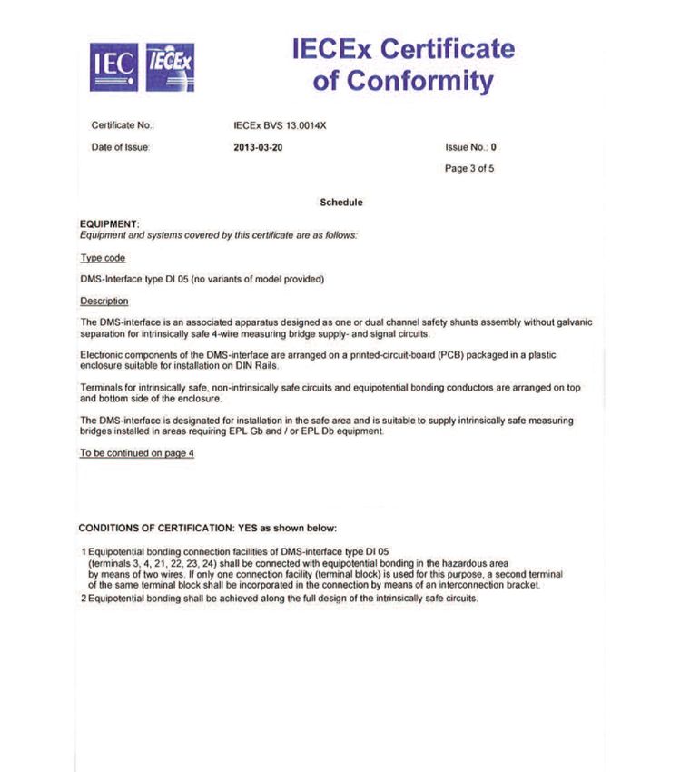
Bedienungsanleitung ExMGZ100/200.ATEX

2.2 Elektrischer Anschluss einkanalig

       Abbildung 1: elektrischer Anschluss einkanalig    ExMGZ_BA_Manual.ai
2.3 Elektrischer Anschluss zweikanalig

       Abbildung 2: elektrischer Anschluss zweikanalig   ExMGZ_BA_Manual.ai

10.03.2020                                                                    4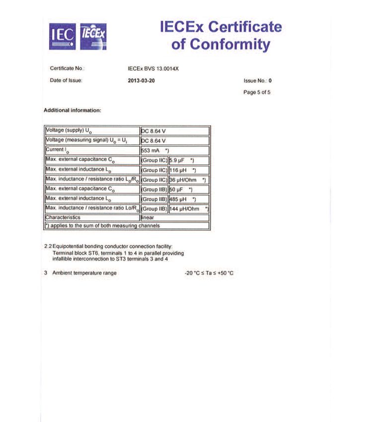
Bedienungsanleitung ExMGZ100/200.ATEX

2.4 Elektrischer Anschluss LMGZD-Baureihe
    (Doppelbereichskraftmesslager)

       Abbildung 3: elektrischer Anschluss LMGZD-Baureihe      ExMGZ_BA_Manual.ai
2.5 Abmessungen

       Abbildung 4: Abmessungen                     ExMGZ_BA_Manual.ai

10.03.2020                                                                          5
Bedienungsanleitung ExMGZ100/200.ATEX

3 Bescheinigungen, Zertifikate

10.03.2020                              6

Bedienungsanleitung ExMGZ100/200.ATEX

10.03.2020                              7
Bedienungsanleitung ExMGZ100/200.ATEX

10.03.2020                              8
Bedienungsanleitung ExMGZ100/200.ATEX

10.03.2020                              9
Bedienungsanleitung ExMGZ100/200.ATEX

10.03.2020                              10
Bedienungsanleitung ExMGZ100/200.ATEX

10.03.2020                              11
Bedienungsanleitung ExMGZ100/200.ATEX

4 Anleitung des Herstellers

FMS Force Measuring Systems AG   FMS USA, Inc.                      FMS (UK)                       FMS (Italy)
Aspstrasse 6                     2155 Stonington Avenue Suite 119   Aspstrasse 6                   Aspstrasse 6
8154 Oberglatt (Switzerland)     Hoffman Estates,, IL 60169 (USA)   8154 Oberglatt (Switzerland)   8154 Oberglatt (Switzerland)
Tel. 0041 1 852 80 80            Tel. +1 847 519 4400               Tel. +44 (0)1767 221 303       Tel. +39 02 39487035
Fax 0041 1 850 60 06             Fax +1 847 519 4401                fmsuk@fms-technology.com       fmsit@fms-technology.com
info@fms-technology.com          fmsusa@fms-technology.com
www.fms-technology.com

10.03.2020                                                                                                                        12
man_csa_80001248_DI05.qxp_Manual 28.02.20 08:00 Seite 1

                                                          DMS-Interface DI05

                                       MANUAL
                                       CSA 80001248

                                                                Edition February 2020
man_csa_80001248_DI05.qxp_Manual 28.02.20 08:00 Seite 2
Manual CSA 80001248 2
DMS-Interface DI05 Interface DMS DI05
Zielgruppe: Groupe ciblé:
Erfahrene Elektrofachkräfte und unterwiesene Électriciens expérimentés selon la réglementa-
Personen. tion pour la sécurité et la santé et personnel ins-
truit.
Inhalt: Sommaire :
1. Sicherheitshinweise 1. Informations de sécurité
2. Normenkonformität 2. Conformité aux normes
3. Definition der elektrischen Werte 3. Définition des valeurs électriques
4. Kennzeichnung 4. Marquage
5. Installation und Inbetriebnahme 5. Installation et mise en service
6. Instandhaltung und Wartung 6. Entretien et maintenance
7. Entsorgung 7. Élimination
1. Sicherheitshinweise 1. Informations de sécurité
Das DMS-Interface DI05 ist ein zugehöriges L’interface DMS DI05 est un matériel associé
Betriebsmittel nach 22.2 und UL 60079-11 und selon C22.2 et UL 60079-11 et sert au raccorde-
dient der Anschaltung eigensicherer Dehnungs- ment de jauges de contrainte à sécurité intrin-
messstreifen und/oder einfacher elektrischer sèque et/ou de matériel électrique simple.
Betriebsmittel. Le matériel associé est installé en dehors de la
Das zugehörige Betriebsmittel wird ausserhalb zone présentant une atmosphère explosive ou
des explosionsgefährdeten Bereiches oder in dans la zone 2 et il dispose d’un circuit de sortie
der Zone 2 installiert und hat einen eigensiche- à sécurité intrinsèque qui peut être conduit dans
ren Ausgangs-Stromkreis, der in die Bereiche les zones 1 ou 21.
der Zonen 1 oder 21 geführt werden kann.
Les appareils ne sont homologués que pour une
Die Geräte sind nur für eine sachgerechte und utilisation appropriée et conforme à leur destina-
bestimmungsgemässe Verwendung zugelassen. tion.
– Für die Ermittlung der anschaltbaren Werte – Pour la détermination des valeurs de L et C
von L und C bei gemischter Beschaltung pouvant être raccordées, il est possible
kann das Programm iSpark der PTB d’utiliser le programme iSpark de PTB.
genutzt werden.
– Sur demande, ces valeurs peuvent aussi
– Die Werte können auf Rückfrage auch von être fournies par thuba.
thuba geliefert werden.
Pour tous les travaux sur des circuits élec-
Beachten Sie bei allen Arbeiten an den explo- triques antidéflagrants, veuillez respecter les
sionsgeschützten Stromkreisen die nationa- prescriptions nationales concernant la sécu-
len Sicherheits- und Unfallverhütungsvor- rité et la prévention des accidents ainsi que
schriften und die nachfolgenden Sicherheits- les informations de sécurité suivantes conte-
hinweise in dieser Betriebsanleitung, die wie nues dans ce mode d’emploi que nous avons
dieser Text in Kursivschrift abgefasst sind! rédigées en italique comme ce texte.
Edition February 2020 thuba Ltd., CH-4002 Basel
Copyright Switzerlandman_csa_80001248_DI05.qxp_Manual 28.02.20 08:00 Seite 3
Manual CSA 80001248 3
DMS Interface DI05
User group:
Experienced electricians as defined by the Oper-
ating Safety Odinance and properly instructed
personnel.
Content
1. Safety instructions
2. Conformity with standards
3. Definition of electrical values
4. Marking
5. Installation and commissioning
6. Inspection and maintenance
7. Disposal
1. Safety instructions
The DMS interface DI05 is an associated appa-
ratus according to C22.2 and UL 60079-11 and
is used for the activation of intrinsically safe
strain gauges and/or simple electrical apparatus.
The associated apparatus is installed outside the
hazardous area or in Zone 2 and has an intrinsi-
cally safe output circuit that can be fed in areas
in Zone 1 or Zone 21.
The apparatus approvals only apply if the appa-
ratus is used cor-rectly and for the intended pur-
pose.
– The iSpark programme from the PTB can
be used for determining the connectible L
and C values for mixed circuits.
– On request, the values can also be supplied
by thuba.
Whenever work is carried out on explosion-
protected circuits, the national safety and
accident prevention regulations and the fol-
lowing safety instructions that, like this text,
are set in italics shall be observed!
Edition February 2020 thuba Ltd., CH-4002 Basel
Copyright Switzerlandman_csa_80001248_DI05.qxp_Manual 28.02.20 08:00 Seite 4
Manual CSA 80001248 4
2. Normenkonformität 2. Conformité aux normes
Class 2258 04 Class 2258 04
Process control equipment - Intrinsically Safe Process control equipment - Intrinsically Safe
Entity - For Hazardouse Locations Entity - For Hazardouse Locations
Class 2258 84 Class 2258 84
Process control equipment - Intrinsically Safe Process control equipment - Intrinsically Safe
Entity - For Hazardouse Locations - Against US Entity - For Hazardouse Locations - Against US
Standards Standards
CAN/CSA-C22.2 No. 61010-1-12 (r2017) CAN/CSA-C22.2 No. 61010-1-12 (r2017)
Safety Requirements for Electrical Equipment for Safety Requirements for Electrical Equipment for
Measurement, Control, and Laboratory Use - Measurement, Control, and Laboratory Use -
Part. 1: General Requirements Part. 1: General Requirements
CAN/CSA-C22.2 No. 60079-0:2015 CAN/CSA-C22.2 No. 60079-0:2015
Explosive atmospheres - Part 0: Equipment - Explosive atmospheres - Part 0: Equipment -
General requirements General requirements
CAN/CSA-C22.2 No. 60079-11:2014 CAN/CSA-C22.2 No. 60079-11:2014
Explosive atmospheres - Part 11: Equipment Explosive atmospheres - Part 11: Equipment
protection by intrinsic safety ‘i’ protection by intrinsic safety ‘i’
ANSI/UL 61010-1-2016 ANSI/UL 61010-1-2016
Safety Requirements for Electrical Equipment for Safety Requirements for Electrical Equipment for
Measurement, Control, and Laboratory Use - Measurement, Control, and Laboratory Use -
Part. 1: General Requirements Part. 1: General Requirements
ANSI/UL 60079-0-2013 (r2017) ANSI/UL 60079-0-2013 (r2017)
Explosive Atmospheres - Part 0: General requi- Explosive Atmospheres - Part 0: General requi-
rements rements
ANSI/UL 60079-11 sixth edition (March 28 2014) ANSI/UL 60079-11 sixth edition (March 28 2014)
Explosive Atmospheres - Part 11: Equipment Explosive Atmospheres - Part 11: Equipment
Protection by Intrinsic Safety ‘i’ Protection by Intrinsic Safety ‘i’
3. Definition der elektrischen Werte 3. Définition des valeurs électriques
3.1 Anschluss «nicht eigensicher» 3.1 Raccordement «sans sécurité
intrinsèque»
Der Anschluss der nicht eigensicheren Versor-
gungsstromkreise erfolgt an den Klemmen 1..12. Le raccordement des circuits d’alimentation
sans sécurité intrinsèque se fait aux bornes 1 à
Um = 250 Volt AC 12.
Un = 36 Volt DC
In = 150 mA Um = 250 Volt AC
Un = 36 Volt DC
1/2 Versorgung 18..36 Volt DC In = 150 mA
5/8 Speisung der Messspannung vom Ver-
stärker 0..6 Volt DC 1/2 Alimentation 18 à 36 volts DC
6/7 Messsignal Kanal 1 5/8 Alimentation de la tension de mesure de
10/11 Messsignal Kanal 2 l’amplificateur 0 à 6 volts DC
9/12 Bürdenwiderstand für Kanal 2 (Speisung) 6/7 Signal de mesure canal 1
3/4 PA 10/11 Signal de mesure canal 2
9/12 Résistance de charge pour le canal 2 (ali-
mentation)
Edition February 2020 thuba Ltd., CH-4002 Basel
Copyright Switzerlandman_csa_80001248_DI05.qxp_Manual 28.02.20 08:00 Seite 5
Manual CSA 80001248 5
2. Conformity with standards
Class 2258 04
Process control equipment - Intrinsically Safe
Entity - For Hazardouse Locations
Class 2258 84
Process control equipment - Intrinsically Safe
Entity - For Hazardouse Locations - Against US
Standards
CAN/CSA-C22.2 No. 61010-1-12 (r2017)
Safety Requirements for Electrical Equipment for
Measurement, Control, and Laboratory Use -
Part. 1: General Requirements
CAN/CSA-C22.2 No. 60079-0:2015
Explosive atmospheres - Part 0: Equipment -
General requirements
CAN/CSA-C22.2 No. 60079-11:2014
Explosive atmospheres - Part 11: Equipment
protection by intrinsic safety ‘i’
ANSI/UL 61010-1-2016
Safety Requirements for Electrical Equipment for
Measurement, Control, and Laboratory Use -
Part. 1: General Requirements
ANSI/UL 60079-0-2013 (r2017)
Explosive Atmospheres - Part 0: General requi-
rements
ANSI/UL 60079-11 sixth edition (March 28 2014)
Explosive Atmospheres - Part 11: Equipment
Protection by Intrinsic Safety ‘i’
3. Definition of electrical values
3.1 Connection «non-intrinsically safe»
Non-intrinsically safe supply circuits are connect-
ed to terminals 1..12.
Um = 250 Volt AC
Un = 36 Volt DC
In = 150 mA
1/2 Supply 18..36 Volt DC
5/8 Feed of measuring voltage of amplifier
0..6 Volt DC
6/7 Measurement signal Channel 1
10/11 Measurement signal Channel 2
9/12 Load resistance for Channel 2 (Feed)
3/4 PA
Edition February 2020 thuba Ltd., CH-4002 Basel
Copyright Switzerlandman_csa_80001248_DI05.qxp_Manual 28.02.20 08:00 Seite 6
Manual CSA 80001248 6
3.2 Eigensichere Stromkreise 3.2 Circuits avec sécurité intrinsèque
Der eigensichere Ausgangsstromkreis wird an Le circuit de sortie à sécurité intrinsèque est rac-
den blauen Klemmen 13..20 angeschlossen. Für cordé aux bornes bleues 13 à 20. Les bornes 21
den PA sind die Klemmen 21..24 vorbehalten. à 24 sont réservées à la liaison équipotentielle.
Uo = 8,64 Volt Uo = 8,64 Volt
Io = 553 mA Io = 553 mA
Po = 997 mW Po = 997 mW
Li = vernachlässigbar Li = négligeable
Ci = vernachlässigbar Ci = négligeable
Lo = Gruppe IIC 116 µH Lo = groupe IIC 116 µH
Lo = Gruppe IIB 485 µH Lo = groupe IIB 485 µH
Co = Gruppe IIC 5,9 μµF Co = groupe IIC 5,9 μµF
Co = Gruppe IIB 50 µF Co = groupe IIB 50 µF
Kennlinie linear Caractéristique linéaire
4. Kennzeichnung 4. Marquage
4.1 Gasexplosionsgefährdete Bereiche 4.1 Zones explosibles gazeuses
[Ex ib Gb] IIC [Ex ib Gb] IIC
Class I, ‘Suitable outputs to Divison 2’, Groups Class I, ‘Suitable outputs to Divison 2’, Groups
A, B, C, D A, B, C, D
4.2 Staubexplosionsgefährdete Bereiche 4.2 Zones explosibles poussiéreuses
[Ex ib Db] IIIC [Ex ib Db] IIIC
4.2 CSA-Bescheinigungen 4.2 Certification CSA
CSA 80001248 CSA 80001248
4.3 Gehäuseschutzgrad 4.3 Indice de protection du boîtier
– DIN-Schienengerät Schutzart IP 20 – Appareil sur rail DIN, indice de protection
– Eingebaut in Gehäuse min. IP 54 (Standard IP 20
IP 66) – Intégré dans un boîtier d’au moins IP 54
(standard IP 66)
4.4 Umgebungstemperatur
Umgebungstemperatur –20 °C bis 50 °C 4.4 Température ambiante
Température ambiante –20 °C à 50 °C
Edition February 2020 thuba Ltd., CH-4002 Basel
Copyright Switzerlandman_csa_80001248_DI05.qxp_Manual 28.02.20 08:00 Seite 7
Manual CSA 80001248 7
3.2 Intrinsically safe circuits
The intrinsically safe output circuit is connected
to the blue terminals 13..20. Terminals 21..24 are
reserved for the potential equalization.
Uo = 8.64 Volt
Io = 553 mA
Po = 997 mW
Li = negligible
Ci = negligible
Lo = group IIC 116 µH
Lo = group IIB 485 µH
Co = group IIC 5.9 μµF
Co = group IIB 50 µF
Linear characteristic
4. Marking
4.1 Explosive gas atmospheres
[Ex ib Gb] IIC
Class I, ‘Suitable outputs to Divison 2’, Groups
A, B, C, D
4.1 Explosive dust atmospheres
[Ex ib Db] IIIC
4.2 CSA Certification
CSA 80001248
4.3 Degree of protection of enclosure
– DIN rail-mounting unit IP 20
– Built into enclosure min. IP 54 (standard
IP 66)
4.4 Ambient temperature
Ambient temperature –20 °C to 50 °C
Edition February 2020 thuba Ltd., CH-4002 Basel
Copyright Switzerlandman_csa_80001248_DI05.qxp_Manual 28.02.20 08:00 Seite 8
Manual CSA 80001248 8
5. Installation 5. Installation
Für das Errichten und das Betreiben sind die Les règles généralement reconnues selon
allgemeinen Regeln der NEC, nationale Vor- NEC, les prescriptions nationales et la pré-
schriften und diese Betriebsanleitung mass- sente notice sont déterminantes pour l’ins-
gebend. tallation et le service.
5.1 Umgebungstemperatur 5.1 Température ambiante
Zur Einhaltung der zulässigen Oberflächentem- Pour respecter les températures de surface
peraturen darf die Umgebungstemperatur den admissibles, la température ambiante ne doit
Bereich von –20 bis 50 °C nicht unter- bzw. über- pas être inférieure ou supérieure à la plage de
schreiten. Zu beachten sind bei der Betrachtung –20 à 50 °C. Lors de la considération des condi-
der Temperaturverhältnisse auch Einflüsse von tions de température, il faut aussi tenir compte
vorhandenen weiteren Wärmequellen oder Son- de l’influence des autres sources de chaleur pré-
neneinstrahlung. Diese dürfen nicht zur zusätz- sentes ou du rayonnement solaire. Ils ne doivent
lichen Aufheizung der Betriebsmittel führen. pas entraîner un réchauffement supplémentaire
Die Angaben auf dem Typenschild sind verbind- du matériel.
lich! Les indications sur la plaque signalétique font
foi!
5.2 Errichtung
5.2 Mise en place
Zwischen eigensicheren und nicht eigensicheren
Stromkreisen ist ein Fadenmass > 50 mm einzu- Il faut respecter un écart minimum de >50 mm
halten (dies gilt auch ausserhalb des explosions- entre les circuits avec et sans sécurité intrin-
gefährdeten Bereiches). sèque (cela s’applique aussi en dehors de la
zone présentant un risque d’explosion).
Die Geräte können wahlweise errichtet werden:
Les appareils peuvent être installés au choix:
a) ausserhalb des Bereichs mit explosions-
fähiger Atmosphäre a) en dehors de la zone avec une atmosphère
oder explosible
b) innerhalb des Bereichs mit explosionsge- ou
fährdeter Atmosphäre der Zone 2 b) dans la zone 2 de l’atmosphère explosive.
5.2.1 Potentialausgleichsleiter 5.2.1 Liaison équipotentielle
Die Potentialausgleichsleiter-Anschlüsse des Les raccordements pour les liaisons équipoten-
DMS-Interface Typ DI05 (Klemmen 3, 4, 21, 22, tielles de l’interface DMS de type DI05 (bornes
23 und 24) sind mit zwei Leitern mit dem Poten- 3, 4, 21, 22, 23 et 24) doivent être reliés par
tialausgleich des explosionsgefährdeten Berei- deux conducteurs à la liaison équipotentielle de
ches zu verbinden. Wird für diesen Zweck nur la zone avec une atmosphère explosive. Si une
eine Klemmstelle benutzt, muss mittels Einlege- seule borne est utilisée à cette fin, il faut au
brücke mindestens eine zweite Klemmstelle des moins intégrer dans la liaison une deuxième bor-
jeweiligen Klemmenblocks in die Verbindung ne du bloc respectif au moyen d’un pont.
einbezogen werden.
La compensation du potentiel doit être réalisée
Im gesamten Verlauf der eigensicheren Strom- sur l’ensemble des circuits à sécurité intrin-
kreise muss Potentialausgleich bestehen. sèque.
Edition February 2020 thuba Ltd., CH-4002 Basel
Copyright Switzerlandman_csa_80001248_DI05.qxp_Manual 28.02.20 08:00 Seite 9
Manual CSA 80001248 9
5. Installation
For installation and operation, the rules of
generally accepted engineering practice, the
provisions of NEC, national regulations and
the instructions set out in this manual must
be observed.
5.1 Ambient temperature
To maintain to the maximum permissible surface
temperature, the ambient temperature must not
fall below or exceed the range –20 °C to 50 °C.
Influences from other heat sources or exposure
to sunlight shall also be taken into consideration
when evaluating the temperature conditions.
These must not cause any additional heating of
the apparatus.
The data stated on the type label is binding!
5.2 Erection
A clearance of >50 mm shall be maintained
between intrinsically safe and non-intrinsically
safe circuits (this also applies outside the haz-
ardous area).
According to requirements, the apparatus can be
installed:
a) outside the hazardous area
or
b) inside hazardous areas in Zone 2
5.2.1 Potential equalization conductor
The potential equalization connections of the
DMS interface, type DI05, (terminals 3, 4, 21, 22,
23 and 24) shall be connected to the potential
equalization of the hazardous area by means of
two conductors. If only one terminal point is used
for this purpose, at least one other terminal point
shall be incorporated in the connec-tion using a
bridge link.
Potential equalization shall exist throughout the
intrinsically safe circuits.
Edition February 2020 thuba Ltd., CH-4002 Basel
Copyright Switzerlandman_csa_80001248_DI05.qxp_Manual 28.02.20 08:00 Seite 10
Manual CSA 80001248 10
5.2.2 Gasexplosionsgefährdete Bereiche 5.2.2 Zones explosibles gazeuses
Die eigensicheren Stromkreise des DMS-Inter- Les circuits à sécurité intrinsèque de l’interface
face Typ DI05 dürfen in Bereiche mit brennba- DMS de type DI05 peuvent être conduits dans
rem Gas der Zone 1 geführt werden. des secteurs avec des gaz inflammables de la
zone 1.
5.2.3 Staubexplosionsgefährdete Bereiche
Die eigensicheren Stromkreise des DMS-Inter- 5.2.3 Zones explosibles poussiéreuses
face Typ DI05 dürfen in Bereiche mit brennba- Les circuits à sécurité intrinsèque de l’interface
rem Staub der Zone 21 geführt werden. Es ist DMS de type DI05 peuvent être conduits dans
jedoch sicherzustellen, dass die Betriebsmittel des secteurs avec des poussières inflammables
an diese eigensicheren Stromkreise angeschlos- de la zone 21. Il faut toutefois s’assurer que le
sen werden, die Anforderungen des EPL Db matériel raccordé à ces circuits à sécurité intrin-
(Zone 21) erfüllen und entsprechend ge-kenn- sèque répond aux exigences de l’EPL Db (zone
zeichnet sind. 21) et qu’il porte le marquage correspondant.
5.2.4 Errichtung in Bereichen, die ein Geräte- 5.2.4 Mise en place dans des zones qui
schutzniveau Gc (EPL) der Betriebs- demandent un niveau de protection Gc
mittel erfordern. (EPL) pour le matériel
5.2.4.1Gehäuse 5.2.4.1Boîtier
Die Steckklemmen für die nicht-eigensicheren Les bornes enfichables pour les circuits sans
Stromkreise und die Potentialausgleichsleiter sécurité intrinsèque et les liaisons équipoten-
dürfen nicht unter Spannung getrennt werden. tielles ne doivent pas être déconnectées sous
tension.
5.3 Zusammenschaltung
5.3 Interconnexion
Die Zusammenschaltung mit den eigensicheren
Betriebsmitteln ist nach den technischen Regeln L’interconnexion avec le matériel à sécurité
zu prüfen (siehe auch CEC Part I und NEC). intrinsèque doit être vérifiée sur la base des
règles techniques (voir aussi CEC Part I et
NEC).
6. Prüfung und Instandhaltung 6. Contrôle et entretien
Die für die Prüfung und Instandhaltung gel- Les instructions d’utilisation applicable du
tende Betriebsanleitung des Herstellers, ist fabricant doivent être respectées pour l’ins-
einzuhalten. Im Rahmen der Wartung sind pection, l’entretien et la maintenance. Dans
vor allem Teile zu prüfen, von denen die le cadre des inspections et des travaux d’en-
Zündschutzart abhängt. tretien, tous les éléments dont dépend le
mode de protection devront être vérifiés.
Das Funktionsverhalten der Geräte ist auch über
lange Zeiträume stabil, eine regelmässige Jus-
Le fonctionnement des appareils est également
tage oder ähnliches entfällt somit. Auch sonst
stable sur de longues périodes. Un ajustement
sind keinerlei Wartungsarbeiten erforderlich.
ou un réglage régulier n’est donc pas nécessai-
Sobald Störungen des Gerätes zu bemerken re. D’autre part, aucun travail de maintenance
sind, bauen Sie das Gerät aus. Die Innenteile n’est requis.
können kundenseitig nicht gewartet werden.
Senden Sie das Gerät an den Hersteller zur Prü- Dès que des dysfonctionnements de l’appareil
fung. sont constatés, il doit être retiré. Les compo-
Edition February 2020 thuba Ltd., CH-4002 Basel
Copyright Switzerlandman_csa_80001248_DI05.qxp_Manual 28.02.20 08:00 Seite 11
Manual CSA 80001248 11
5.2.2 Explosive gas atmospheres
The intrinsically safe circuits of the DMS inter-
face, type DI05, may be fed into Zone 1explosive
gas atmospheres.
5.2.3 Explosive dust atmospheres
The intrinsically safe circuits of the DMS inter-
face, type DI05, may be fed into Zone 21explo-
sive dust atmospheres. However, it is necessary
to ensure that the apparatus is connected these
intrinsically safe circuits, meets the requirements
of EPL Db (Zone 21) and is marked accordingly.
5.2.4 Installation in areas requiring EPL Gc
5.2.4.1Enclosure
The plug-in terminals for the non-intrinsically
safe circuits and the potential equalization con-
ductor must not be disconnected when live.
5.3 Interconnection
The interconnection with intrinsically safe appa-
ratus shall be tested according to the technical
rules and regulations (see also CEC Part I and
NEC).
6. Inspection and maintenance
The valid operating manual of the manufac-
turer shall be observed for inspection, main-
tenance and repair. During servicing, it is par-
ticularly important to check those compo-
nents upon which the type of protection
depends.
The functional characteristics of the apparatus
shall remain stable over long periods of time,
thus eliminating the need for regular adjustment
or similar. Also, no other maintenance work is
required.
As soon as malfunctions are observed, disas-
semble the apparatus. Internal parts cannot be
serviced by the customer. Return the apparatus
Edition February 2020 thuba Ltd., CH-4002 Basel
Copyright Switzerlandman_csa_80001248_DI05.qxp_Manual 28.02.20 08:00 Seite 12
Manual CSA 80001248 12
Sicherungen dürfen nicht durch den Betreiber sants internes ne peuvent pas être entretenus
gewechselt werden, da gleichzeitig auch die par le client. Envoyez l’appareil au fabricant pour
betroffenen Zenerdioden zu ersetzen sind. Diese qu’il soit contrôlé.
Arbeiten erfolgen einen Abgleich, der nur im Her-
stellerwerk durchgeführt werden kann. Les fusibles ne doivent pas être changés par
l’exploitant car les diodes Zener doivent être
remplacées au même moment. Ces travaux
6.1 Störungsbeseitigung nécessitent un réglage qui ne peut être effectué
que dans l’usine du fabricant.
An Geräten, die in Verbindung mit explosionsge-
fährdeten Bereichen betrieben werden darf kei-
6.1 Dépannage
ne Veränderung vorgenommen werden. Repa-
raturen am Gerät dürfen nur von speziell hierfür Aucune modification ne doit être apportée sur
ausgebildetem und berechtigtem Fachpersonal les appareils qui sont utilisés dans le contexte
ausgeführt werden. Im Normalfall sind defekte d’atmosphères explosives. Les réparations sur
Geräte an den Hersteller zurückzusenden. l’appareil ne doivent être effectuées que par des
spécialistes qualifiés et autorisés. En règle
générale, les appareils défectueux doivent être
retournés au fabricant.
7. Entsorgung 7. Élimination
Die Entsorgung der Verpackung und der ver- L’emballage et les composants usagés doivent
brauchten Teile hat gemäss den Bestimmungen être éliminés conformément aux dispositions du
des Landes, in dem das Gerät installiert wird, zu pays dans lequel l’appareil a été installé.
erfolgen.
Edition February 2020 thuba Ltd., CH-4002 Basel
Copyright Switzerlandman_csa_80001248_DI05.qxp_Manual 28.02.20 08:00 Seite 13
Manual CSA 80001248 13
to the manufacturer for testing.
Fuses must not be replaced by the operator as
the affected Zener diodes also have to be
replaced at the same time. These tasks require
adjustment, and this can only be carried out in
the manufacturer’s works.
6.1 Fault elimination
Changes must not be made to apparatus oper-
ated in connection with hazardous areas.
Repairs to apparatus shall only be carried out by
specially trained and authorized specialists. Nor-
mally faulty apparatus shall be returned to the
manufacturer.
7. Disposal
Any packaging and used parts shall be disposed
of in accordance with the regulations that apply
in the country in which the apparatus is installed.
Edition February 2020 thuba Ltd., CH-4002 Basel
Copyright Switzerland+$=$5'286 &/$66,),(' /2&$7,21 121+$=$5'286/2&$7,21
'06,QWHUIDFH7\SH',
Copyright
,QWULQVLFDOO\6DIH&RQQHFWLRQV 1RQ,QWULQVLFDOO\6DIH&RQQHFWLRQV
Edition February 2020
$Q\6LPSOH$SSDUDWXV RUDSSURYHGGHYLFHZLWK(QWLW\&RQFHSW
SDUDPHWHUV 9PD[,PD[&L/L DSSURSULDWHIRUFRQQHFWLRQWR$VVRFLDWHG
$SSDUDWXVZLWK(QWLW\&RQFHSWSDUDPHWHUVOLVWHGRQWKHULJKWVLGH
>([LE*E@,,&
>([LE'E@,,,&
Manual CSA 80001248
&ODVV,=RQH>([LE*E@,,&
&ODVV,=RQH>$([LE'E@,,,&
man_csa_80001248_DI05.qxp_Manual 28.02.20 08:00 Seite 14
Remarques
1. Le concept d’entité permet l’interconnexion d’appareils à sécurité intrinsèque avec des appareils connexes qui n’ont pas été spécifiquement examinés en tant
que système lorsque les valeurs approuvées de Voc (ou Uo), Isc (ou Io) et Po pour l’appareil connexe sont inférieures ou égales à Vmax (Ui) et Imax (Ii)
pour l’appareil à sécurité intrinsèque et que les valeurs approuvées de Ca (Co) et La (Lo) pour l’appareil connexe sont supérieures à Ci + Ccâble et Li +
Lcâble, respectivement, pour l’appareil à sécurité intrinsèque.
Lorsque la capacité et l’inductance par pied ne sont pas connues, les valeurs suivantes doivent être utilisées : Ccâble = 60 pF/ft, Lcâble = 0,2 µH/ft.
2. Appareil simple : un composant électrique ou une combinaison de composants de construction simple avec des paramètres électriques bien définis qui ne
génèrent pas plus de 1,5 volt, 100 milliampères et 25 milliwatts, ou un composant passif qui ne consomme pas plus de 1,3 watt et est compatible avec la
sécurité intrinsèque du circuit dans lequel il est utilisé (États-Unis). Un thermocouple ou un dispositif résistif non inductif de commutation (Canada).
3. Les méthodes de câblage doivent être conformes aux règlementations électriques du pays d’utilisation.
4. Les circuits à sécurité intrinsèque doivent être câblés et séparés en se conformant à l’article 504.20 ou aux autres réglementations locales, s’il y a lieu.
5. La barrière ne doit être connectée à aucun dispositif qui utilise ou génère en interne une tension supérieure à 250 V Rms ou DC sauf s’il a été établi que le
dispositif isole de manière adéquate la tension de la barrière.
6. Il n’est pas nécessaire de raccorder les barrières à la terre.
7. Dans les zones dangereuses, les bornes 3, 4, 21, 22, 23, 24 (installations de liaison équipotentielle) doivent être raccordées à la liaison équipotentielle à l’ai-
de de deux conducteurs.
8. La liaison équipotentielle doit être garantie pour l’ensemble du circuit à sécurité intrinsèque.
9. L’interface DMS est certifiée en tant que composant destiné à être monté dans un boîtier approprié où l’assemblage final est soumis à l’approbation de l’auto-
rité locale compétente.
10. AVERTISSEMENT : La substitution de composants peut compromettre la sécurité intrinsèque.
Switzerland
thuba Ltd., CH-4002 Basel
14$70263+Ê5(6(;3/26,9(6 $70263+Ê5(6121(;3/26,9(6
'06,QWHUIDFH7\SH',
Copyright
&RQQH[LRQjVpFXULWpLQWULQVqTXH &RQQH[LRQVDQVVpFXULWpLQWULQVqTXH
Edition February 2020
7HQVLRQ DOLPHQWDWLRQ
7RXWDSSDUHLOVLPSOH RXGLVSRVLWLIDSSURXYpDYHFGHVSDUDPqWUHV
9PD[,PD[&L/L GHFRQFHSWG¶HQWLWp DSSURSULpVSRXUOH 7HQVLRQ VLJQDOGHPHVXUH 8R 8L
UDFFRUGHPHQWjXQDSSDUHLOFRQQH[HDYHFOHVSDUDPqWUHVGHFRQFHSW &RXUDQW,R
G¶HQWLWpOLVWpVVXUOHF{WpGURLW
&DSDFLWpH[WHUQHPD[&R
,QGXFWDQFHH[WHUQHPD[ /R
>([LE*E@,,&
5DSSRUWLQGXFWDQFHUpVLVWDQFHPD[ /R5R
>([LE'E@,,,&
Manual CSA 80001248
&DSDFLWpH[WHUQHPD[&R
man_csa_80001248_DI05.qxp_Manual 28.02.20 08:00 Seite 15
&ODVV,=RQH>([LE*E@,,&
&ODVV,=RQH>$([LE'E@,,,& ,QGXFWDQFHH[WHUQHPD[ /R
5DSSRUWLQGXFWDQFHUpVLVWDQFHPD[ /R5R
&DUDFWpULVWLTXHV /LQpDLUH
6¶DSSOLTXHjODVRPPHGHVGHX[FDQDX[PHVXUpV
Notes
1. The Entity Concept allows interconnection of intrinsically safe apparatus with associated apparatus not specifically examined in combination as a system
when the approved values of Voc (or Uo), Isc (or Io) and Po for the associated apparatus are less than or equal to Vmax (Ui) and Imax (Ii) for the intrinsically
safe apparatus and the approved values of Ca (Co) and La (Lo) for the associated apparatus are greater than Ci + Ccable and Li + Lcable, respectively, for
the intrinsically safe apparatus. Where the capacitance and inductance per foot are not known, the following values shall be used: Ccable = 60 pF/ft., Lcable
= 0.2 µH/ft.
2. Simple Apparatus: An electrical component or combination of components of simple construction with well defined electrical parameters that does not genera-
te more than 1.5 volts, 100 milliamps, and 25 milliwatts, or a passive component that does not dissipate more than 1.3 watts and is compatible with the intrin-
sic safety of the circuit in which it is used (USA). A switch non-inductive resistive device or thermocouple (Canada).
3. Wiring methods must be in accordance with the electrical code of the country in use.
4. Intrinsically safe circuits must be wired and separated in accordance with Article 504.20 or other local codes, as applicable.
5. The Barrier shall not be connected to any device which uses or generates internally any voltage in excess of 250V Rms or DC unless the device has been
determined to adequately isolate the voltage from the barrier.
6. Connection of barriers to ground is not required.
7. Terminals 3, 4, 21, 22, 23, 24 (equipotential bonding facilities) shall be connected to equipotential bonding in hazardous area by means of two conductors.
8. Equipotential bonding shall be ensured for the complete intrinsically safe loop.
9. The DMS interface is certified as component item for mounting in a suitable enclosure where the final assembly is subject to the acceptance by the local aut-
hority having jurisdiction.
10. WARNING: Substitution of components may impair intrinsic safety.
15
Switzerland
thuba Ltd., CH-4002 Baselman_csa_80001248_DI05.qxp_Manual 28.02.20 08:00 Seite 16
Manual CSA 80001248 16
Certificate of Compliance
Certificate: 80001248 Master Contract: 254834
Project: 80001248 Date Issued: December 13, 2019
Issued to: Thuba Ltd.
Stockbrunnerain 9
4123 Allschwill
SWITZERLAND
Attention: Mr. Peter Thurnherr
The products listed below are eligible to bear the CSA Mark shown
(*LXVWL
Issued by:
E.Giusti
PRODUCTS
CLASS 2258 04 - PROCESS CONTROL EQUIPMENT - Intrinsically Safe, Entity – For Hazardous Locations
CLASS 2258 84 - PROCESS CONTROL EQUIPMENT - Intrinsically Safe, Entity – For Hazardous Locations –
Against US Standards
[Ex ib Gb] IIC
[Ex ib Db] IIIC
Class I, Zone 1, [Ex ib Gb] IIC
Class I, Zone 21, [AEx ib Db] IIIC
DMS Interface Model DI 05, rated 36Vdc, 150 mA max. (supply terminals: 1 and 2) and 6Vdc for bridge signal
and supply (terminals: 5, 6, 7, 8 and 10, 11) is a DIN rail module.
DMS Interface is an associated intrinsically safe apparatus designed as single or dual channel safety shunts
assembly dedicated to 4-wire bridge supply and signal circuits.
The DMS interface is designed for installation in non-hazardous (unclassified) area and provides intrinsically safe
signals to Zone 1 and 21 bridges. Um is limited to 250V ac.
Intrinsically safe when installed per drawing S34319_FMS.
DQD 507 Rev. 2019-04-30 © 2018 CSA Group. All rights reserved. Page 1
Edition February 2020 thuba Ltd., CH-4002 Basel
Copyright Switzerlandman_csa_80001248_DI05.qxp_Manual 28.02.20 08:00 Seite 17
Manual CSA 80001248 17
Certificate: 80001248 Master Contract: 254834
Project: 80001248 Date Issued: December 13, 2019
Intrinsically safe output circuits are defined as follows:
Voltage (supply) Uo/Voc DC 8.64 V
Voltage (measuring signal) Uo = Ui DC 8.64 V
Current Io=Isc 553 mA *)
Max. external capacitance Co/Ca IIC 5.9 µF *)
Max. external inductance Lo/La IIC 116 µH *)
Max. inductance / resistance ratio Lo / Ro IIC 36 µH/ȍ *)
Max. external capacitance Co/Ca IIB 50 µF *)
Max. external inductance Lo/La IIB 485 µH *)
Max. inductance / resistance ratio Lo/Ro IIB 144 µH/ ȍ *)
Characteristics linear
*) applies to the sum of both measuring channels
Ambient temperature range from -20°C Ta 50°C.
Conditions of Acceptability:
- Terminals 3, 4, 21, 22, 23, 24 (equipotential bonding facilities) shall be connected to equipotential bonding in
hazardous area by means of two conductors.
- Equipotential bonding shall be ensured for the complete intrinsically safe loop.
- The DMS interface is certified as component item for mounting in a suitable enclosure where the final
assembly is subject to the acceptance by the local authority having jurisdiction.
APPLICABLE REQUIREMENTS
CAN/CSA-C22.2 No. 61010-1-12 Safety Requirements for Electrical Equipment for Measurement, Control,
and Laboratory Use - Part 1: General Requirements
CAN/CSA-C22.2 No. 60079-0:19 Explosive atmospheres - Part 0: Equipment – General requirements
CAN/CSA-C22.2 No. 60079-11:14 Explosive atmospheres – Part 11: Equipment protection by intrinsic
safety “i”
ANSI/UL 61010-1-2016 Safety Requirements for Electrical Equipment for Measurement, Control,
and Laboratory Use - Part 1: General Requirements
ANSI/UL 60079-0-2019 Explosive atmospheres – Part 0: Equipment – General requirements
ANSI/UL 60079-11 Explosive Atmospheres – Part 11: Equipment Protection by Intrinsic
Sixth Edition (March 28, 2014) Safety “i”
DQD 507 Rev. 2019-04-30 © 2018 CSA Group. All rights reserved. Page 2
Edition February 2020 thuba Ltd., CH-4002 Basel
Copyright Switzerlandman_csa_80001248_DI05.qxp_Manual 28.02.20 08:00 Seite 18
Manual CSA 80001248 18
Certificate: 80001248 Master Contract: 254834
Project: 80001248 Date Issued: December 13, 2019
MARKINGS
The manufacturer is required to apply the following markings:
• Products shall be marked with the markings specified by the particular product standard.
• Products certified for Canada shall have all Caution and Warning markings in both English and French.
Additional bilingual markings not covered by the product standard(s) may be required by the Authorities Having
Jurisdiction. It is the responsibility of the manufacturer to provide and apply these additional markings, where
applicable, in accordance with the requirements of those authorities.
The products listed are eligible to bear the CSA Mark shown with adjacent indicators 'C' and 'US' for Canada and
US (indicating that products have been manufactured to the requirements of both Canadian and U.S. Standards) or
with adjacent indicator 'US' for US only or without either indicator for Canada only.
Method of Marking:
Marking label is manufactured by TESA, model 6930Laser-Label. The material is listed under file
PGGU2.MH18055.
• Manufacturer’s name: "Thuba Ltd.", or CSA Master Contract Number “254834”, adjacent to the CSA Mark in
lieu of manufacturer’s name.
• Model designation: As specified in the PRODUCTS section, above.
• Electrical ratings: As specified in the PRODUCTS section, above.
• Ambient temperature rating: As specified in the PRODUCTS section, above.
• Manufacturing date in MMYY format, or serial number, traceable to year and month of manufacture.
• Enclosure ratings: As specified in the PRODUCTS section, above.
• The CSA Mark, as shown on the Certificate of Conformity.
• The designation “CSA 19CA80001248X”
• Hazardous Location designation: As specified in the PRODUCTS section, above.
• Temperature code: As specified in the PRODUCTS section, above.
“WARNING — DO NOT SEPARATE WHEN ENERGIZED.” and “AVERTISSEMENT – NE PAS
DEBRANCHER TANT QUE LE CIRCUIT EST SOUS TENSION.”
• Hazardous Location Method of Protection markings (Ex markings): “ASSOCIATED
EQUIPMENT/APPAREILLAGE CONNEXE for Class I, Zone 1 and 21, [Ex ib Gb] IIC and [Ex ia Db] IIIC”
and “Class I, Zone 1 [AEx ib Gb] IIC and [AEx ia Db] IIIC”. The word “Class” may be abbreviated “CL”, the
word “Groups” may be abbreviated “GRP” or “GP”. The words: “ASSOCIATED EQUIPMENT/
APPAREILLAGE CONNEXE”, may be substituted with “ASSOCIATED APPARATUS/ APPAREILLAGE
CONNEXE”, or “ASSOCIATED DEVICE/ APPAREILLAGE CONNEXE”.
• The following words:
o “[Ex ib]”.
o The words: “ASSOCIATED EQUIPMENT/ APPAREILLAGE CONNEXE”
o “WARNING: Substitution of components may impair intrinsic safety.”
o “AVERTISSEMENT : LA SUBSTITUTION DE COMPOSANTS PEUT COMPROMETTRE
LA SECURITE INTRINSEQUE”
o “Install per drawing FMS_S343319.”
DQD 507 Rev. 2019-04-30 © 2018 CSA Group. All rights reserved. Page 3
Edition February 2020 thuba Ltd., CH-4002 Basel
Copyright Switzerlandman_csa_80001248_DI05.qxp_Manual 28.02.20 08:00 Seite 19
Manual CSA 80001248 19
Supplement to Certificate of Compliance
Certificate: 80001248 Master Contract: 254834
The products listed, including the latest revision described below,
are eligible to be marked in accordance with the referenced Certificate.
Product Certification History
Project Date Description
80001248 December 13, 2019 Original cCSAus certification
DQD 507 Rev. 2019-04-30 © 2018 CSA Group. All rights reserved. Page 1
Edition February 2020 thuba Ltd., CH-4002 Basel
Copyright Switzerlandman_csa_80001248_DI05.qxp_Manual 28.02.20 08:00 Seite 20
Ihr Partner für international
zertifizierte Lösungen
im Explosionsschutz.
Entwicklung und Produktion Rohr- und Tankbegleitheizungen
Explosionsgeschützte Schaltgeräte- – Wärmekabel
kombinationen · Wärmekabel mit Festwiderstand
· mineralisolierte Wärmekabel
Geräteschutzniveau EPL Gb*
· selbstbegrenzende Wärmekabel
– Druckfeste Kapselung «db»
– Montagen vor Ort
– Erhöhte Sicherheit «eb»
– Temperaturüberwachungen
– Überdruckkapselung «pxb»
· Thermostate und
Geräteschutzniveau EPL Gc* Sicherheitstemperaturbegrenzer
– Erhöhte Sicherheit «ec» · elektronische Temperaturregler und
– Schwadenschutz «nR» Sicherheitsabschalter
– Überdruckkapselung «pzc» · Fernbedienungen zu Temperaturregler
– Widerstandsfühler Pt-100 Geräteschutz-
Geräteschutzniveau EPL Db und EPL Dc*
niveau EPL Ga und Gb*
für staubexplosionsgeschützte Bereiche
– Schutz durch Gehäuse «tb», «tc»
– Überdruckkapselung «pxb», «pzc» Installationsmaterial
Zubehör – Zeitweilige Ausgleichsverbindungen
– Digital-Anzeigen – Erdungsüberwachungssysteme
– Trennschaltverstärker – Klemmen- und Abzweigkästen
– Transmitterspeisegeräte – Motorschutzschalter bis 63 A
– Sicherheitsbarrieren – Sicherheitsschalter 10–180 A
– Tastatur und Maus (mittelbare und unmittelbare Abschaltung)
– Bildschirm – Steckvorrichtungen
– Industrie-PC – Reinraumsteckdosen
– Befehls- und Meldegeräte
– kundenspezifische Befehlsgeber
Leuchten – Kabelrollen (max. 3 Flanschsteckdosen)
Geräteschutzniveau EPL Ga, Gb, Gc und EPL – Kabelverschraubungen
Da, Db, Dc* – Montagematerial
– LED Hand- und Rohrleuchten 5–58 Watt
– LED Langfeldleuchten 18–58 Watt
Akkreditierte Inspektionsstelle (SIS 145)
(auch mit integrierter Notbeleuchtung)
– Druckfeste LED-Rohre (Ersatz für Um den ordnungsgemässen Betrieb und die
FL-Röhren) Sicherheit zu gewährleisten, werden Anlagen in
– Signalsäulen explosionsgefährdeten Bereichen besonders
– Strahler genau geprüft. Wir bieten fachgerechte Erstprü-
– Sicherheitsbeleuchtung fungen und wiederkehrende Prüfungen an. Die-
– Blitzleuchten se bestehen jeweils aus einer Ordnungsprüfung
– Kesselflanschleuchten und einer technischen Prüfung.
Elektrische Heizeinrichtungen Service Facilities nach IECEx Scheme
für Industrieanwendungen
Als IECEx Scheme Service Facility sind wir qua-
– Luft- und Gaserwärmung (bis 100 bar) lifiziert, weltweit Reparaturen, Überholungen und
– Flüssigkeitsbeheizungen Regenerierungen durchzuführen – auch an
– Reaktorbeheizungen (HT-Anlagen) Fremdgeräten.
– Beheizung von Festkörpern
– Sonderlösungen *EPL = Equipment Protection Level (Geräteschutzniveau)man_csa_80001248_DI05.qxp_Manual 28.02.20 08:00 Seite 21
Votre partenaire pour les
solutions certifiées
en protection antidéflagrante
Conception et production Chauffages de conduites et de citernes
Ensembles d’appareillage antidéflagrants – câbles thermoconducteurs
· câbles chauffants à résistance fixe
Niveau de protection du matériel EPL Gb*
· câbles chauffants à isolation minérale
– enveloppe antidéflagrante «db»
· câbles chauffants autolimités
– sécurité augmentée «eb»
– montage sur site
– enveloppe en surpression «pxb»
– contrôle de température
Niveau de protection du matériel EPL Gc* · thermostats et limiteurs de température
– sécurité augmentée «ec» de sécurité
– respiration limitée «nR» · thermorégulateurs électroniques et
– surpression interne «pzc» rupteurs de sécurité
· télécommandes de thermorégulateur
Niveau de protection du matériel EPL Db et
– capteurs à résistance Pt-100 Niveau de pro-
EPL Dc* pour zones protégées contre les
tection du matériel EPL Ga et Gb
explosions de poussière
– Protection par enveloppes «tb», «tc»
– surpression interne «pxb», «pzc» Matériel de montage et d’installation
Accessoires – Liason temporaire
– affichage (visuel) numérique – Dispositifs de contrôle de la mise à la terre
– amplificateurs de séparations – boîtes à bornes et de jonction
– appareils d’alimentation transmetteurs – disjoncteurs-protecteurs jusqu’à 63 A
– barrières de sécurité – interrupteurs de sécurité 10 à 180 A
– clavier et souris (coupure directe ou indirecte)
– écran – connecteurs
– PC industriel (ordinateur industriel) – prises de courant pour salles blanches
– appareils de commande
Luminaires – postes de commande selon spécifications
client
Niveau de protection du matériel EPL Ga, Gb,
– dévidoirs de câble (max. 3 prises encastrable)
Gc et Da,Db, Dc*
– presse-étoupe
– LED luminaires tubulaires et baladeuses
– matériel de montage
5 à 58 watts
– luminaires linéaires 18 à 58 watts
(aussi avec éclairage de secours intégré) Organe d’inspection accrédité (SIS 145)
– tubes LED antidéflagrants (en remplace- Dans le but d’assurer une exploitation correcte
ment des tube FL) et la sécurité, les installations en atmosphère
– balise lumineuse explosive doivent être inspectées de manière
– projecteurs particulièrement approfondie. Nous proposons
– éclairage de secours également, en plus d’un premier examen, des
– lampes éclair inspections de routine et des vérifications pério-
– luminaires à bride pour chaudières diques.
Chauffages électriques pour applications
Service clients selon le modèle IECEx
industrielles
– chauffages de l’air et de gaz (jusqu’à 100 Par notre service clients certifié selon le modèle
bars) IECEx nous sommes qualifiés pour procéder
– chauffages de liquides dans le monde entier aux réparations, révisions
– chauffages à réacteur (thermostables) et remises en état des équipements, même ceux
– chauffages de corps solides d’autres fabricants.
– solutions spécifiques
*EPL = Equipment Protection Level (Niveau de protection du
matériel)man_csa_80001248_DI05.qxp_Manual 28.02.20 08:00 Seite 22
Your partner for internationally
certified solutions
in explosion protection
Design and Production Pipe and tank trace heating systems
Explosionproof switchgear assemblies – heating cables
· heating cables with fixed resistors
Equipment protection level EPL Gb
· mineral-insulated heating cables
– flameproof enclosure ‘db’
· self-limiting heating cables
– increased safety ‘eb’
– site installation
– pressurized enclosure ‘pxb’
– temperature monitoring systems
· thermostats and safety temperature
Equipment protection EPL level Gc
limiters
– increased safety ‘ec’
· electronic temperature controllers and
– restricted breathing enclosure ‘nR’
safety cutouts
– pressurized enclosure ‘pzc’
· remote controls for temperature
controller
Equipment protection level EPL Db and Dc
– resistance temperature detectors Pt-100
for areas at risk of dust explosions
Equipment protection level EPL Ga and Gb
– protection by enclosure ‘tb’, ‘tc’
– pressurized enclosure ‘pxb’, ‘pzc’
Accessories Installation material
– digital displays
– temporary bonding
– disconnect amplifiers
– earth monitoring systems
– transmitter power packs
– terminals and junction boxes
– safety barriers
– motor protecting switches up to 63 A
– keyboard and mouse
– safety switches 10 to 180 A
– monitor
(indirect and direct tripping)
– industrial PC
– plug-and-socket devices
– clean room power outlets
– control and indicating devices
Lamps
– customized control stations
Equipment protection level EPL Ga, Gb, Gc – cable reels (max. 3 flange sockets)
and EPL Da, Db, Dc – cable glands
– LED hand lamps and tube lights 5 to 58 W – fastening material
– LED linear luminaires 18 to 58 W
(also with integrated emergency lighting)
– flameproof LED-tubes (Replacement for Accredited inspection body (SIS 145)
fluorescent tubes)
Extremely strict inspections are carried out to
– signal towers
guarantee the correct operation and safety of
– reflector lamps
installations in hazardous areas. We carry out
– safety lighting
both professional initial inspections and periodic
– flashing lamps
inspections. These consist of a documentation
– boiler flange lamps
and organisation check and a technical inspecti-
on.
Electric heaters for industrial applications
– heating of air and gases (up to 100 bar) Service Facilities
– heating of liquids according to IECEx Scheme
– reactor heating systems (HT installations)
As an IECEx Scheme service facility we are qua-
– heating of solids
lified to carry out repairs, overhauling and rege-
– special solutions
neration work all over the world – even on equip-
ment from other manufacturers.man_csa_80001248_DI05.qxp_Manual 28.02.20 08:00 Seite 23
man_csa_80001248_DI05.qxp_Manual 28.02.20 08:00 Seite 24

                                                           thuba Ltd.
                                                           CH-4002 Basel

                                                           Phone   +41 61 307 80 00
                                                           Fax     +41 61 307 80 10
                                                                   customer.center@thuba.com
                                                                   www.thuba.com
Sie können auch lesen