DNSR-2R2 Original Betriebsanleitung Original Instruction Manual - wir sind sicherheit. we are safety - DINA ...
←
→
Transkription von Seiteninhalten
Wenn Ihr Browser die Seite nicht korrekt rendert, bitte, lesen Sie den Inhalt der Seite unten
DNSR-2R2
 Original Betriebsanleitung
Original Instruction Manual

        wir sind sicherheit.
              we are safety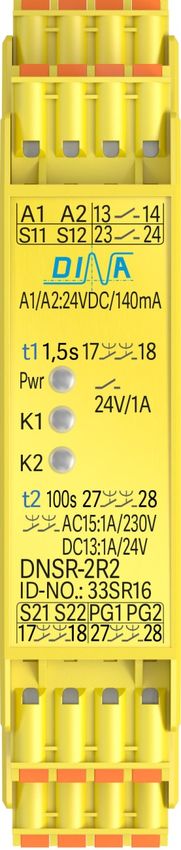
DNSR-2R2   Original Betriebsanleitung                Original Instruction Manual

             Stand 30.08.2017           Seite 2 von 16       Date 2017-08-30       Page 2 of 16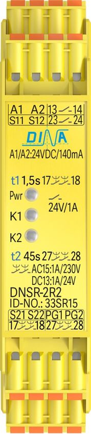
DNSR-2R2      Original Betriebsanleitung                 Original Instruction Manual

EU-Konformitätserklärung                    EU declaration of conformity
Dichiarazione di conformità UE             Dichiarazione di conformità UE         Declaración UE de conformidad

Die nachfolgend aufgeführten Produkte sind konform mit den Anforderungen der folgenden Richtlinien
The beneath listed products are in conformity with the requirements of the following directives
Les produits mentionés ci-dessous sont conformes aux exigences imposées par les directives suivantes
I prodotti sotto elencati sono conformi alle direttive sotto riportate
Los productos listados a continuación son conforme a los requisitos de las siguientes directivas

Maschinenrichtlinie        2006/42/EG      EMV Richtlinie         2014/30/EU      RoHS-Richtlinie        2011/65/EU
Machinery directive        2006/42/EC      EMC Directive          2014/30/EU      RoHS Directive         2011/65/EU
Directive Machines         2006/42/CE      Directive de CEM       2014/30/UE      Directive de RoHS      2011/65/UE
Direttiva Macchine         2006/42/CE      Direttiva EMV          2014/30/UE      Direttiva RoHS         2011/65/UE
Directiva de máquinas      2006/42/CE      Directiva CEM          2014/30/UE      Directiva RoHS         2011/65/UE

Folgende Normen sind angewandt:            a   •   DIN EN 61326-1: 2005-05 (klasse B), DIN EN 61326-3-1: 2008 +2009
Following standards are used:              b   •   DIN EN 61326-3-1: 2008 +2009
Les normes suivantes sont appliquées:          •   DIN EN 60947-5-1
Vengono applicate le seguenti norme:       c   •   ISO DIN EN 13849-1/ Teil 1/ Kategorie 3, PLd
Se utilizan los siguientes estándares:     d   •   DIN EN ISO 13849-2

Zusatzanforderung:                             GS-ET-20
Supplementary requirements:                    DIN EN ISO 9001: 2015/ DQS, Frankfurt, Reg.-Nr.:67542-01

Bezeichnung der Bauteile         Descrizione dei componenti DNSR2R2 Not-Halt Relais
Description of components        Descripción de componente                   Emergency stop relay
Description des composants

EG-Baumusterprüfbescheinigung        EC-Type Test certificate       ET 16095 vom 04.07.2016   ET 16095 from2016.07.04

Notifizierte Stelle Organismo notificato                    Fachausschuss für Elektrotechnik,
Notified body       Organismo notificado                    Prüf- und Zertifizierungsstelle Köln, Germany
                                                            Europäisch notifizierte Stelle - Kenn-Nummer 0340,
Organisme notifié

Bevollmächtigte Person für die     Authorized person for the        Dirar Najib
Erstellung dieser Unterlagen       issue of this document           Esslinger Str. 84/ 72649 Wolfschlugen/ Germany

Wolfschlugen, 13. März 2018

Dirar Najib

Geschäftsführer/ CEO

                Stand 30.08.2017           Seite 3 von 16         Date 2017-08-30         Page 3 of 16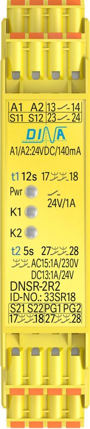
DNSR-2R2    Original Betriebsanleitung                Original Instruction Manual

Inhaltsverzeichnis                                 Seite Contents                                        Page

Bestimmungsgemäße Verwendung                         5    Intended purpose                                5

Zertifizierungsdaten                                 5    Certification data                              5

Sicherheitsbestimmungen                              6    Safety regulations                              6

Wichtiger Hinweis und Validierung                    7    Important notes and validation                  7

Anschlussklemmen 33SR20                              8    Connection terminals 33SR20                     8

Produktbeschreibung 33SR20                           8    Product description 33SR20                      8

Verwendung 33SR20                                    9    Usage 33SR20                                    9

Zeiteinstellung 33SR20                               9    Time adjustment 33SR20                          9

Anzeige und Verhalten im Fehlerfall 33SR20           9    Display and Performance on failure 33SR20       9

Applikationsbeispiel 33SR20                          10   Application example 33SR20                      10

Anschlussklemmen 33SR15, 33SR16, 33SR17,             11   Connection terminals 33SR15, 33SR16, 33SR17,    11
33SR18                                                    33SR18

Produktbeschreibung 33SR15, 33SR16, 33SR17,          11   Product description 33SR15, 33SR16, 33SR17,     11
33SR18                                                    33SR18

Verwendung 33SR15, 33SR16, 33SR17, 33SR18            11   Usage 33SR15, 33SR16, 33SR17, 33SR18            11

Anzeige und Verhalten im Fehlerfall 33SR15-          12   Display and Performance on failure 33SR15-      12
33SR18                                                    33SR18

Applikationsbeispiel 33SR15-33SR18                   12   Application example 33SR15-33SR18               12

Technische Daten                                     13   Technical data                                  14

Kontaktlebensdauer                                   13   Contact life                                    14

Abmessungen                                          15   Dimension                                       15

Einbau                                               15   Fitting                                         15

Ausbau                                               15   Remove                                          15

               Stand 30.08.2017          Seite 4 von 16         Date 2017-08-30        Page 4 of 16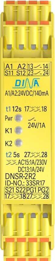
DNSR-2R2       Original Betriebsanleitung                Original Instruction Manual

Bestimmungsgemäße Verwendung                                 Intended purpose
Prüfgrundlage:                                               Testing based on:

• DIN EN 61326-1: 2005-05 (klasse B),                        • DIN EN 61326-1: 2005-05 (class B),
  DIN EN 61326-3-1: 2008 +2009: Elektrische Mess-,             DIN EN 61326-3-1: 2008 + 2009: electrical measuring,
  Steuer-, Regel- und Laborgeräte – EMV-                       control, rule and laboratorial equipment-EMC-
  Anforderungen                                                requirements

• DIN EN 60947-5-1: Niederspannungsschaltgeräte-             • DIN EN 60947-5-1: Low-voltage switchgear; part 5.1:
  Teil 5-1: Steuergeräte und Schaltelemente;                   control gear and switching elements -
  Elektromechanische Steuergeräte                              electromechanical control gear

• ISO DIN EN 13849-1: Sicherheit von Maschinen -             • ISO DIN EN ISO 13849-1: Safety-related parts of control
  Sicherheitsbezogene Teile von Steuerungen Teil 1             systems; Part 1: Safety of machinery category 3, PLd
  Kategorie 3, PLd,                                            EC-Type Test Certificate: ET 16095 from 2016-07-04
  Baumusterprüfbescheinigung: ET 16095 vom
  04.07.2016                                                 • DIN EN ISO 13849-2:
• DIN EN ISO 13849-2: Sicherheitsbezogene Teile von            Safety-related parts of control systems; Part 2:
  Steuerungen Teil 2: Validierung und folgenden                Validation
  Prüfgrundsätzen:                                             and follow test principles

• GS-ET-20: Zusatzanforderungen für die Prüfung und • GS-ET-20: supplementary requirements for testing and
  Zertifizierung von Sicherheitsschaltgeräten                  certification of safety switchgear

                                                 Zertifizierungsdaten             Certification data

                                                 MTTFd: 98 Jahre                  MTTFd: 98 years
                                                 DCavg: niedrig                   CCF: 75 points
                                                 CCF: 75 Punkte                   DCavg: low
                                                 PFHd: 1,14 x 10⁻⁷ PLd            CCF:75 points
                                                 Schalthäufigkeit: 1/h            Frequency of operation: 1/h
                                                 Gebrauchsdauer 20 Jahre          Operation time 20 years

Zertifizierung durch den Fachausschuss für                    Certificated by: (Fachausschuss für Elektrotechnik,
Elektrotechnik, Prüf- und Zertifizierungsstelle Köln,         Prüf- und Zertifizierungsstelle Köln), European notified
Europäisch notifizierte Stelle - Kenn-Nummer 0340,            institution, Identification-number 0340, EC-Type Test
EG Baumusterprüfungsbescheinigung                             certificate
(DGUV Test: : ET 16095 vom 04.07.2016)                        (DGUV Test: : ET 16095 from 04.07.2016)
EMV-Richtlinie bescheinigt durch ELMAC GmbH                   EMC-directive certificated by “ELMAC GmbH Bondorf”,
Bondorf,                                                      Reg. No.: DAT-P-206/05-00
Reg. Nr.: DAT-P-206/05-00
QM System zertifiziert nach DIN EN ISO 9001:2015 durch QM System certificated according to DIN EN ISO
DQS, Frankfurt, Reg.-Nr.:67542-01                             9001:2015 by “DQS, Frankfurt”, Reg.-No.: 67542 QM08

Zertifikat: Siehe www.dina.de                                 Certificate: See www.dina.de

                 Stand 30.08.2017           Seite 5 von 16         Date 2017-08-30          Page 5 of 16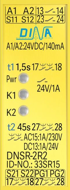
DNSR-2R2     Original Betriebsanleitung                Original Instruction Manual

Sicherheitsbestimmungen                                     Safety regulations

• Das Gerät darf nur von einer Elektrofachkraft oder        • The unit may only be installed and operated by those
 unterwiesenen Personen installiert und in Betrieb           who are qualified electrical engineers or have
 genommen werden, die mit dieser Betriebsanleitung und received sufficient training and are familiar with both
 den geltenden Vorschriften über Arbeitssicherheit und       these instructions and the current regulations for
 Unfallverhütung vertraut sind.                              safety at work and accident prevention.
• Beachten Sie die VDE- sowie die örtlichen Vorschriften,   • Follow VDE, EN as well as local regulations especially
 insbesondere hinsichtlich der Schutzmaßnahmen.              as regards preventative measures!
• Halten Sie beim Transport, der Lagerung und im Betrieb • Transport, storage and operating conditions should
 die Bedingungen nach EN 60068-2-6, 04/95 ein.               all stick to EN 60068-2-1, 2-2.
• Werden die Vorschriften nicht beachtet, kann Tod,         • Ignoring the safety regulations can lead to death,
 schwere Körperverletzungen oder hoher Sachschaden           serious injury or cause considerable damage!
 die Folge sein.                                            • In emergency stop applications must ensure that the
• Bei Not-Halt Anwendungen muss der automatische             machine cannot start up again automatically!
 Wiederanlauf der Maschine verhindert werden.               • Any guarantee is void following unauthorised
• Durch eigenmächtige Umbauten erlischt jegliche             modifications. This can lead to death, serious injury or
 Gewährleistung. Es können dadurch Gefahren                  cause considerable damage!
 entstehen, die zu hohen Sachschaden, schweren              • The unit should be mounted in a cabinet with a
 Verletzungen oder sogar zum Tod führen.                     protection class of IP54. Otherwise dampness and
• Montieren Sie das Gerät in einen Schaltschrank; Staub      dust could lead to functional impairment. The
 und Feuchtigkeit können sonst zu Beeinträchtigungen         installation in a control cabinet is imperative.
 der Funktionen führen. Der Einbau in einem                 • Adequate fuse protection must be provided on all
 Schaltschrank ist zwingend.                                 output contacts especially with capacitive and
• Sorgen Sie an allen Ausgangskontakten bei kapazitiven      inductive loads.
 und induktiven Lasten für eine ausreichende                • The unit must be installed following the specification
 Schutzbeschaltung.                                          of DIN EN 50274, VDE 0660-514 regarding the
• Das Gerät ist unter Berücksichtigung der nach DIN EN       required distances.
 50274, VDE 0660-514 geforderten Abstände einzubauen. • During operation, parts of the electronic switchgear

• Während des Betriebes stehen Schaltgeräte unter            carry high voltage. The protective covers must not be
 gefährlicher Spannung. Schutzabdeckungen dürfen             removed.
 nicht entfernt werden.                                     • The device must be replaced after the first
• Wechseln Sie das Gerät aus nach dem ersten Fehlerfall      malfunction and properly disposed after reaches the
 und entsorgen Sie es sachgerecht nach Ablauf der            end of it service life.
 Lebensdauer!

• Bewahren Sie diese Produktinformation auf!                • Keep the operating instructions!

                   Stand 30.08.2017       Seite 6 von 16        Date 2017-08-30          Page 6 of 16
DNSR-2R2 Original Betriebsanleitung                Original Instruction Manual
Wichtiger Hinweis und Validierung                       Important notes and validation
• Das hier beschriebene Produkt wurde entwickelt, um    • The product described here was developed to
 als Teil eines Gesamtsystems sicherheitsgerichtete          perform safety related functions as part of a
 Funktionen zu übernehmen.                                   complete system.
• Das Gesamtsystem wird durch Sensoren, Auswerte-,         • The complete system consists of sensors, evaluation
  Melde-einheiten sowie Konzepte für sichere                 and message units as well as concepts for safe
  Abschaltungen gebildet.                                    shutdowns.
• Es liegt im Verantwortungsbereich des Herstellers einer • It is the responsibility of the manufacturer of a
  Anlage oder Maschine die korrekte Gesamtfunktion           system or machine to ensure the proper overall
  sicherzustellen.                                           function.
• Der Hersteller der Anlage/Maschine ist verpflichtet, die • The manufacturer of the system is required to test
  Wirksamkeit des implementierten Sicherheitskonzepts        and to document the effectiveness of the
  innerhalb des Gesamtsystems zu prüfen und zu               implemented safety concept within the complete
  dokumentieren.                                             system.

• Dieser Nachweis ist nach jeglicher Modifikation am       • This verification is to be performed after every
  Sicherheitskonzept bzw. Sicherheitsparametern erneut       modification to the safety concept or to safety
  zu erbringen.                                              parameters.
• DINA Elektronik GmbH ist nicht in der Lage, alle         • DINA Elektronik is not in the position to guarantee
  Eigenschaften eines Gesamtsystems, das nicht durch         the properties a complete system that was not
  DINA konzipiert wurde, zu garantieren.                     designed by DINA.
• DINA Elektronik GmbH übernimmt auch keine Haftung • DINA Elektronik GmbH also accepts no liability for
  für Empfehlungen, die durch die nachfolgende               recommendations that are given or implied by the
  Beschreibung gegeben bzw. impliziert werden.               following description.
• Auf Grund der nachfolgenden Beschreibung können          • No new guarantee, warranty or liability claims that
  keine neuen, über die allgemeinen Lieferbedingungen        extend beyond DINA's general delivery conditions
  der DINA Elektronik GmbH hinausgehenden Garantie-,         can be derived on the basis of the following
  Gewährleistungs- oder Haftungsansprüche abgeleitet         description.
  werden.

• Zur Vermeidung von EMV-Störgrößen müssen die             • To avoid EMC disturbances, the physical
  physikalischen Umgebungs- und Betriebsbedingungen          environmental and operating conditions at the
  am Einbauort des Produkts dem Abschnitt EMV der            installation location of the product must comply
  DIN EN 60204-1 entsprechen.                                with section EMC of DIN EN 60204-1.

                  Stand 30.08.2017       Seite 7 von 16         Date 2017-08-30        Page 7 of 16
DNSR-2R2 Original Betriebsanleitung Original Instruction Manual
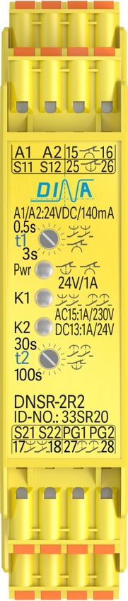
Anschlussklemmen 33SR20 Connection terminals 33SR20
A1: 24V DC/ A2: 0V A1: 24V DC/ A2: 0V
S11: Steuereingang, 15V DC±0,5V S11: Control input, 15V DC±0,5V
für 15 16 und 17 18 for 15 16 and 17 18
S12: Steuerspannung, 15V DC S12: Control voltage, 15V DC
S21: Steuereingang, 12V DC±0,5V S21: Control input, 12V DC±0,5V
für 25 26 und 27 28 for 25 26 and 27 28
S22: Steuerspannung (12V DC) S22: Control voltage, 12V DC
PG1/ PG2: Zeiteinstellungsfreigabe PG1/ PG2: Time adjustment enabling for
für t1 und t2 über Drahtbrücke t1 and t2 via wire connection
15 16: Diagnosekontakt, 15 16: Diagnostics contact
anzugsverzögert (t1). ON-delayed (t1).
17 18: Sicherer Kontakt, 17 18: Safe contact
rückfallverzögert (t1) OFF-delayed (t1)
25 26: Diagnosekontakt, 25 26: Diagnostics contact
rückfallverzögert (t2). OFF-delayed (t2).
27 28: Sicherer Kontakt, 27 28: Safe contact
anzugsverzögert (t2) ON-delayed (t2)
Produktbeschreibung 33SR20 Product description 33SR20
• DNSR-2R2 verfügt über rückfall- und anzugs- • DNSR-2R2 has OFF and ON time delayed
verzögerte Kontakte zur Freigabe von contacts to enable control circuits.
Steuerstromkreisen.
• Der Anschlussplan ist am Gerät seitlich. • The connection schematic is at the unit side t.
• Die steckbaren Klemmen sind Vertausch sicher. • The pluggable terminals are interchange safe.
• Durch Verbinden S11 mit S12 schließt der Kontakt • By connecting S11 to S12 the contact 17-18 closes
17-18 unverzögert und 15-16 öffnet. undelayed and the contact 15-16 opens.
• Durch Unterbrechen S11 von S12 öffnet 17-18 • By disconnecting S11 of S12 17-18 opens
zeitverzögert und 15-16 schließt. LED K1 blinkt. OFF-delayed and 15-16 closes. LED K1 is flashing.
• Die Funktion ist nicht retriggerbar. • The function is not retrigger able.
• Durch Verbinden S21 mit S22 schließt der • By connecting S21 to S22 the contact 27-28
Kontakt 27-28 zeitverzögert und 25-26 öffnet. closes ON-delayed and 25-26 opens. LED K2 is
LED K2 blinkt. flashing.
• Durch Unterbrechen S21 von S22 öffnet 27-28 • By disconnecting S21 to S22 the contact 27-28
unverzögert und 25-26 schließt. opens undelayed and 25-26 closes.
Hinweis zu den Kontakten 15-16 und 25-26 Remark to the contacts 15-16 and 25-26
• Diese sind (NO) Kontakte funktional invertiert zu den • These are NO contacts functional inverted to the
Kontakten 17-18 und 27-28. contacts 17-18 and 27-28.
• Die Kontakte 15-16 und 25-26 sind ohne • The contacts 15-16 and 25-26 are open without power
Betriebsspannung offen und können nur unter supply. They can be used for quit function only during
Spannung zur Quittierung verwendet werden. power on.
Stand 30.08.2017 Seite 8 von 16 Date 2017-08-30 Page 8 of 16DNSR-2R2 Original Betriebsanleitung Original Instruction Manual
Verwendung 33SR20 Usage 33SR20
DNSR-2R2 ist geeignet zum Einsatz beispielsweise zur: DNSR-2R2 is adapted to be used as example to:
• Energietrennung von den Antrieben über den sicheren • Turn off the power of the drives with safe contact
rückfallverzögerten Kontakt 17 18. 17 18.
• Entriegelung von Schutzeinrichtungen über den • Enable the protection device with the safe contact
sicheren anzugsverzögerten Kontakt 27 28. 27 28.
• DNSR-2R2 kann in Sicherheitskreisen nach VDE 0113 • DNSR-2R2 can be used in safety circuits according to
Teil 1 eingesetzt werden mit maximal Kategorie 3/ PLd VDE 0113 part 1 with maximal category 3 / PLd
nach DIN EN ISO 13849-1. according to DIN EN ISO 13849-1.
• DNSR-2R2 ist in 22.5mm Kunststoffgehäuse zur • DNSR-2R2 is mounted in a 22.5mm synthetically
Montage im Schaltschrak auf einer 35mm Hutschiene. housing to be installed on a 35mm DIN rail.
• Ein Anschlussplan ist an der Geräteseite. • A connection plan is on the side of the unit.
Zeiteinstellung 33SR20 Time adjustment 33SR20
• Einstellung der Zeitverzögerung der Kontakte (15-16, 17- • The adjustment of the time delay for the contacts
18) und (25-26, 27-28) erfolgt frontseitig über je ein (15-16, 17-18 and 25-26, 27-28) happens in the front
Potentiometer. panel via 2 Potentiometer.
• Eine Einstellung ist nur möglich bei gebrückten PG1/ • An adjustment is possible if PG1 is connected to PG2.
PG2.
• Die Zeitübernahme erfolgt nur bei inaktiven S12 und • The time storage happens if S12 and S22 are inactive.
S22. (t1) für (15-16, 17-18), (t2) für (25-26, 27-28). (t1) is for (15-16, 17-18) (t2) is for (25-26, 27-28).
• Nach der Einstellung ist die Brücke zu entfernen. • After the adjustment PG1 and PG2 have to be unwired.
• Die Einstellungen sind im Gerät gespeichert. • The adjustments are stored in the unit.
• Die Validierung der Zeit nach Einstellungen ist wichtig. • The time has to be validated after every adjustment.
Anzeige und Verhalten im Fehlerfall 33SR20 Display and Performance on failure 33SR20
24V DC A1/A2: ON S11 S12: K1 , 17 18, 15 16 S21 S22: K2 , 27 28, 25 26
S11 S12: K1 (t1 17 18 ) S21 S22: K2 (t2 27 28),
t1=0: K1 , 17 18, 15 16 t2=0: K2 , 27 28, 25 26
Verbunden Nicht verbunden Verbunden mit Connected Not connected ►Connected to
S11/S12 S21/S22 17-18 15-16 27-28 25-26 LED K1 LED K2
PG1 PG2 X X 0,5Hz 0,5Hz
Start S11 S12 S21 S22
S11 S22 S11 S12 S22 15V
S21 S12 S12 12V S21 S22
A1 S12 S12 24V S21 S22
A1 S11 S11 24V S21 S22 4Hz 1Hz
A1 S22 S11 S12 S22 24V
A1 S21 S11 S12 S21 24V 1Hz 4Hz
S11 S12 S11 S12 S21 S22
S11, S12 S22 S11 S12 S21 S22
S11, S12 S21 S11 S12 12V S21 S22 1Hz 4Hz
S21,S22 S12 t2 S11 S12 S21 S22 1Hz
S21, S22 S12 t2 S11 S12 S21 S22
S21,S22 S11 t2 S11 S12 S21 S22/S22 S11 1Hz 4Hz
S21,S22 S11 t2 S11 S12 S21 S22/S22 S11 1Hz 4Hz
Stand 30.08.2017 Seite 9 von 16 Date 2017-08-30 Page 9 of 16DNSR-2R2 Original Betriebsanleitung Original Instruction Manual
Applikationsbeispiel 33SR20 Funktionsdiagramm
Application example 33SR20 Function diagram
Pwr
S11 S12
1 2 5 6 3 4 7 8 3x400V AC 17-18 t1
A1 A2 S11 S12 15 16 25 26 15-16 t1
24V DC 0V 15V Pwr
ID-No: 33SR20 t1 t2 U1 V1W 1
12V 12V S21 S22
S21 S22 PG1 PG2 17 18 27 28 3 27-28 t2
9 10 11 12 13 14 15 16 W2 U2 V2 25-26 t2
t
V V
Stand 30.08.2017 Seite 10 von 16 Date 2017-08-30 Page 10 of 16DNSR-2R2 Original Betriebsanleitung Original Instruction Manual
Anschlussklemmen 33SR15 bis 33SR18 Connection terminals 33SR15 to 33SR18
A1: 24V DC, A2: 0V A1: 24V DC, A2:0V
S11: Steuereingang (15V DC±0,5V) S11: Control input (15V DC±0,5V)
für 17 18 for 17 18
S12: Steuerspannung (15V DC) S12: Control voltage (15V DC)
S21: Steuereingang (12V DC±0,5V) S21: Control input (12V DC±0,5V)
für 27 28 for 27 28
S22: Steuerspannung (12V DC) S22: Control voltage (12V DC)
PG1/ PG2: Steuereingänge über 24V DC PG1/ PG2: Control inputs via 24V DC
für 13 14 und 23 24 for 13 14 and 23 24
13 14: Startkontakt steuerbar über PG1. 13 14: Start contact controlled via PG1
Andere Funktionen sind möglich. Other functions are possible.
17 18: Sicherer Kontakt, 17 18: Safe contact
rückfallverzögert (t1) OFF-delayed (t1)
23 24: Startkontakt steuerbar über 23 24: Start contact controlled via PG2
PG2 Andere Funktionen sind möglich Other functions are possible.
27 28: Sicherer Kontakt 27 28: Safe contact OFF-delayed (t2)
rückfallverzögert (t2)
Produktbeschreibung 33SR15 bis 33SR18 Product description 33SR15 to 33SR18
• DNSR-2R2 verfügt über rückfallverzögerte Kontakte • DNSR-2R2 has OFF-delayed contacts to enable
zur Freigabe von Steuerstromkreisen. control circuits.
• Der Anschlussplan ist am Gerät seitlich. • The connection schematic is at the side of the unit.
• Die steckbaren Klemmen sind Vertausch sicher. • The pluggable terminals are coded against
• Durch verbinden der Klemme PG1 zu 24V DC schließt interchange.
der Kontakt 13 14 und öffnet sofort nach der • 13 14 closes by connecting the terminal PG1 to
Trennung. 24V DC and opens after disconnecting.
• 17 18 schließt bei Verbinden S11 mit S12. • 17 18 closes by connecting S11 to S12.
• 17 18 öffnet rückfallverzögert (t1) beim • 17 18 opens OFF-delayed by disconnecting S11
Unterbrechen S11 von S12. LED K1 blinkt während (t1). of S12. LED K1 is flashing during (t1).
• Die Funktion ist retriggerbar bei ID-No.: 33SR15, 33SR16 • The function is retrigger able at ID-No.: 33SR15,
und 33SR18. 33SR16 and 33SR18.
• Der Kontakt 23 24 schließt beim Verbinden der • 23 24 closes by connecting the terminal PG2 to
Klemme PG2 mit 24V DC und öffnet bei Trennung. 24V DC and opens after disconnecting.
• 27 28 schließt bei Verbinden S21 mit S22. • 27 28 closes by connecting S21 to S22.
• 27 28 öffnet rückfallverzögert (t2) beim • 17 18 opens OFF-delayed by disconnecting S21
Unterbrechen S21 von S22. LED K2 blink während (t2) of S22. LED K2 is flashing during (t2).
Verwendung 33SR15 bis 33SR18 Usage 33SR15 to 33SR18
DNSR-2R2 ist geeignet zum Einsatz beispielsweise zur: DNSR-2R2 is adapted to be used as example to:
• Energietrennung von den Antrieben über sichere rück- • Turn off the power of the drives with safe contact
fallverzögerten Kontakt 17 18 und 27 28. 17 18 and 27 28.
• DNSR-2R2 kann in Sicherheitskreisen nach VDE 0113 • DNSR-2R2 can be used in safety circuits according to
Teil 1 eingesetzt werden mit maximal Kategorie 3/ PLd VDE 0113 part 1 with maximal category 3 / PLd
nach DIN EN ISO 13849-1. according to DIN EN ISO 13849-1.
• DNSR-2R2 ist in 22.5mm Kunststoffgehäuse zur • DNSR-2R2 is mounted in a 22.5mm synthetically
Montage im Schaltschrak auf einer 35mm Hutschiene. housing to be installed on a 35mm DIN rail.
• Ein Anschlussplan ist an der Geräteseite. • A connection plan is on the side of the unit.
Stand 30.08.2017 Seite 11 von 16 Date 2017-08-30 Page 11 of 16DNSR-2R2 Original Betriebsanleitung Original Instruction Manual
Anzeige und Verhalten im Fehlerfall 33SR15 bis 33SR18 Display and Performance on failure 33SR15 to 33SR18
24V DC A1/A2: S11 S12: K1 17 18 S21 S22: K2 27 28
ON
S11 S12: K1 (t1 17 18) S21 S22: K2 (t2 27 28)
t1=0: K1 17 18 t2=0: K2 27 28
Verbunden Nicht verbunden Verbunden mit Connected Not connected Connected to
S11/S12 S21/S22 17-18 27-28 LED K1 LED K2
Start/Pwr S11 S12 S21 S22
S11 S22 S11 S12 S22 15V
S21 S12 S12 12V S21 S22
A1 S12 S12 24V S21 S22
A1 S11 S11 24V S21 S22 4Hz 1Hz
A1 S22 S11 S12 S22 24V
A1 S21 S11 S12 S21 24V 1Hz 4Hz
S11 S12 S11 S12 S21 S22
S11, S12 S22 S11 S12 S21 S22
S11, S12 S21 S11 S12 12V S21 S22 1Hz 4Hz
S21,S22 S12 t2 S11 S12 S21 S22 1Hz
S21, S22 S12 t2 S11 S12 S21 S22
S21,S22 S11 t2 S11 S12 S21 S22/S22 S11 1Hz 4Hz
S21,S22 S11 t2 S11 S12 S21 S22/S22 S11 1Hz 4Hz
Applikationsbeispiel 33SR15-18 Funktionsdiagramm
Application example 33SR15-18 Function diagram
Pwr
7/23 S11 S12
17-18 t1
1 2 5 6 3 4 7 8 3x400V AC
A1 A2 S11 S12 13 14 23 24 PG1
24V DC 0V 15V 13-14 t1
ID-No: 33SR20 t1 t2 U1 V1W 1 Pwr
12V 12V
S21 S22 PG1 PG2 17 18 27 28 3 S21 S22
9 10 11 12 13 14 15 16 W2 U2 V2
27-28 t2
8/24 V V PG1
24V 23-24
Stand 30.08.2017 Seite 12 von 16 Date 2017-08-30 Page 12 of 16DNSR-2R2 Original Betriebsanleitung Original Instruction Manual
Technische Daten
Allgemeine technische Daten
Betriebsspannung 24VDC +/- 10%
Stromaufnahme ca. 80mA in Ruhestellung, ca. 140mA in Wirkstellung
Sicherung Intern PTC Sicherung 200mA
Betriebstemperatur -10°C bis +60°C
Lagertemperatur -40°C bis +80°C
Rüttel- und Schockfestigkeit in allen Ebenen Sinus 10–50 Hz, 0,35mm, 10 Zyklen, 1 Oktave / 5g
Anschlussquerschnitt 0.25-2,5mm² mit Aderendhülse
Anschlussklemmen Federkraft steckbar und kodiert/ Polyamide PA
Anschlussdraht 60/75°C Kupfer
Gehäusematerial Polyamid PA nicht verstärkt
Schutzart Für Schaltschrankeinbau ≥ IP 54, Klemmen IP20
Bemessungsisolationsspannung 250V AC, nicht für die Kontakte 15-16 und 25-26
Technische Daten der Eingänge
S12 15V ± 0.5V nur ansteuerbar über S11
S22 12V ± 0.5V nur ansteuerbar über S21
Technische Daten der Kontaktausgänge
Rückfallverzögerung (t1) für 17-18 0,5-3s (t1 ist bei 15-16 Anzugsverzögerung)
bei ID-No.: 33SR20
Anzugsverzögerung (t2) für 27-28 30-100s (t2 ist bei 25-26 Rückfallverzögerung)
bei ID-No.: 33SR20
Rückfallverzögerung (t1) für 17-18 33SR15 und 33SR16: 1,5s / 33SR17 und 33SR18: 12s
Rückfallverzögerung (t2) für 27-28 33SR15: 45s/ 33SR16: 100s/ 33SR17 und 33SR18: 5s
Schaltstrom der Kontakte 15-16 und 25-26 Minimal 24V/3mA, maximal 30V/0.5A,
Absicherung 3A träge
Schaltstrom der Kontakte 13-14 und 23-24 Minimal 24V/3mA, maximal 30V/0.5A,
Absicherung 3A träge
Schaltvermögen AC1: 250V/3A, DC1: 30V/3A, 1,5x 10⁵ Schaltspiele,
nach IEC/EN 60947-4-1, 17-18 und 27-28 Absicherung 3Aträge
Schaltvermögen AC15: 250V/ 0.2A, DC13: 30V/ 0.2A, 106 Schaltspiele
nach IEC/EN 60947-5-1 nur für 17-18, 27-28
Schaltvermögen AC15: 250V/1A, DC13: 30V/1A, 1.5x10⁵ Schaltspiele
nach IEC/EN 60947-5-1, 17-18 und 27-28
Kurzschlussfestigkeit / Vorsicherung 200A/ B6 Automat / 800A/ 6A Schmelzsicherung gG
Mechanische Lebensdauer > 20 x 106 Schaltspiele
Kontaktwerkstoff AgNi10
Maximale Schaltspiele nur für 17-18 und 27-28 360 Zyklen/h bei max. Schaltstrom AC15+DC13
Bemessungsisolationsspannung 17-18 und 27-28: 250V AC / 15-16 und 25-26: 30V
Stoßspannungsfestigkeit Verschmutzungsgrad 2 4KV nur für 17-18 und 27-28
Ansprechzeit/ Rückfallzeit Typisch 10ms / Typisch 6ms
Gewicht 150g
Kontaktlebensdauer
1000
500
Schaltspiele x 1000/ Cycles x 1000
AC1: 250V
AC15: 250V DC1: 30V
DC13: 30V
100
50
10 0.1 0.5 1.0 2.0 3.0 4.0
Schaltstrom (A) / Switching current (A) 5.0
Stand 30.08.2017 Seite 13 von 16 Date 2017-08-30 Page 13 of 16DNSR-2R2 Original Betriebsanleitung Original Instruction Manual
Technical data
General technical data
Power supply 24VDC +/- 10%
Current drain ca. 80mA relay off, ca. 140mA relay on
Fuse Internal PTC fuse 200mA
Operating temperature -10°C to +60°C /
Storage temperature 40°C to +80°C
Vibration and Shock resistance in all 3 level Sin 10 – 50 Hz, 0,35mm, 10 cycles, 1 Octave / 5g
Cable cross section 0.25-2,5mm² with wire end sleeve
Connection terminals/ Materiel Spring load clamps, pluggable/ Polyamide PA
Connection wire 60/75°C copper
Housing material Polyamide PA non-reinforced
Protection class Installation in a closed cabinet with ≥ IP54, terminals: IP20
Rated Isolation voltage 250V AC not for the contacts 15-16 and 25-26
Technical data of the inputs
S12 15V ± 0.5V, internal at S11, S33 test against other voltage
S22 12V ± 0.5V, internal at S21, S43 test against other voltage
Technical data of the contact outputs
OFF-time delay (t1) for 17-18 0.5 - 3s (t1 is for 15-16 ON time delay) with ID-No.: 33SR20
ON-time delay (t2) for 27-28 30-100s (t2 is for 25-26 OFF-time delay) with ID-No.: 33SR20
OFF-time delay (t1) for 17-18 1,5s at ID-No.: 33SR15 and 33SR16, 12s at 33SR17, 33SR18
OFF-time delay (t2) for 27-28 45s at ID-No.: 33SR15, 100s at 33SR16, 5s at 33SR17, 33SR18
Switch current; contacts AC1: 250V/3A, DC1: 30V/3A, 1.5x10⁵ cycles
according to IEC/EN 60947-4-1 for 17-18, 27-28 only
Switch current according to IEC/EN 60947-5-1 for 17- AC15: 250V/0.2A, DC13: 30V/0.2A, 106 cycles
18, 27-28 only
Switch current according to AC15: 250V/1A, DC13: 30V/1A, 1.5x10⁵ cycles
IEC/EN 60947-5-1 for 17-18, 27-28 only
Switch current; contacts 15-16 and 25-26 Minimal 24V/3mA, maximal 30V/0.5A, fuse 3A slow
Switch current; contacts 13-14 and 23-22 Minimal 24V/3mA, maximal 30V/0.5A, fuse 3A slow
Short-circuit strength / line fuse 200A/ B6 automat / 800A/safety fuse 6A gG
Mechanical life > 20 x 106 cycles
Contact material AgNi10
Maximal cycles for 17-18, 27-28 only 360 cycles/h with maximal switch current AC15 + DC13
Isolation voltage 17-18 and 27-28: 250V AC/ 15-16 and 25-26: 30V
Impulse withstand voltage 4KV, for the contacts 17-18 and 27-28 only
pollution degree 2 environment
Reaction time / Drop out time Typical 10ms / Typical 6ms
Wight 150g
Contact life
1000
500
Schaltspiele x 1000/ Cycles x 1000
AC1: 250V
AC15: 250V DC1: 30V
DC13: 30V
100
50
10 0.1 0.5 1.0 2.0 3.0 4.0
Schaltstrom (A) / Switching current (A) 5.0
Stand 30.08.2017 Seite 14 von 16 Date 2017-08-30 Page 14 of 16DNSR-2R2 Original Betriebsanleitung Original Instruction Manual
Abmessungen Dimension
111 22.5
114
Einbau Fitting Ausbau Remove
(2) (3)
(1)
70-75mm 70-75mm
Stand 30.08.2017 Seite 15 von 16 Date 2017-08-30 Page 15 of 16DNSR-2R2 Original Betriebsanleitung Original Instruction Manual
Wir sind Sicherheit
We are safety.
DINA Elektronik GmbH
Esslinger Str. 84
D72649 Wolfschlugen
Phone +49 7022 95170
Fax +49 7022 9517-710
info@dina.de
www.dina.de
Stand 30.08.2017 Seite 16 von 16 Date 2017-08-30 Page 16 of 16Sie können auch lesen