EINBAUANLEITUNG INSTALLATION GUIDE - Lenkradinterface URI LS2 - Speedsignal Dokumentationen und ...
←
→
Transkription von Seiteninhalten
Wenn Ihr Browser die Seite nicht korrekt rendert, bitte, lesen Sie den Inhalt der Seite unten
EINBAUANLEITUNG
                                   INSTALLATION GUIDE

                                   Lenkradinterface URI LS2
                                       SWRC interface URI LS2

                                      Art. Nr. 3470006

10R-055004

speedsignal GmbH                   Phone:   +49 8061 49518 – 0    E-Mail:   info@speedsignal.de
Carl-von-Ossietzky-Straße 3 + 7    Fax:     +49 8061 49518 – 10   Homepage: www.speedsignal.de
D- 83043 Bad Aibling                                              facebook: facebook.com/speedsignal
DIP-Schalter Einstellung – DIP switches configuration
              Radio                                      Fahrzeug Vehicle
        DIP    1    2   3    4      5     6     7    8
                                                          Peugeot 207 ab 05.2006, 307 ab 2005, 308
                                                          ab 2007, 407 ab 09/2004, 807ab 2002, Ex-
-              1   0    0    0      1      0    0    0
                                                           pert Citroen C 4, C 5 ab 2005, C8, Jumpy;
                                                                            Fiat Scudo
Alpine         0   1    0    0      0      1    0    0                   wie (1), mit PDC
                                                           Lancia Musa, Ypsilon, Fiat Chroma, Stilo,
Kenwood        1   1    0    0      1      1    0    0
                                                                       Grande Punto, Idea
JVC            0   0    1    0      0      0    1    0           Fiat 500, Alfa Mito (Blue&Me)
                                                            Alfa Brera, Alfa Spider 159, Fiat Bravo
Blaupunkt      1   0    1    0      1      0    1    0
                                                                            (Blue&Me)
Clarion        0   1    1    0      0      1    1    0                Alfa 156, Alfa 147, GT
                                                           Alfa 159 ab 05, Brera ab 05, Spider (939)
Panasonic      1   1    1    0      1      1    1    0
                                                                               ab 06
                                                          Fiat Ducato ab 06; Peugeot Boxer, Citroen
Zenec          0   0    0    1      0      0    0    1
                                                                              Jumper
                                                          Chrysler 300C (ohne Ansteuerung Verstär-
Eclipse        1   0    0    1      1      0    0    1
                                                          ker), Dodge Charger, Caliber, Jeep Limited
-              0   1    0    1      0      1    0    1                  Porsche Cayenne
                                                           Mitsubishi Outlander, Citroen C-Crosser,
-              1   1    0    1      1      1    0    1
                                                                          Peugeot 4007
Grundig        0   0    1    1      0      0    1    1                        -
Sony           1   0    1    1      1      0    1    1                        -
Pioneer        0   1    1    1      0      1    1    1                        -
Becker         1   1    1    1      1      1    1    1                        -

                                                                           = CAN aktiv
                                                                             CAN active

                                                                           = Ausgang Kl. 15 aktiv
                                                                             Output ignition active

3470006_R7                              05.07.2021                                        Seite 2 von 4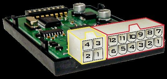
Pin Belegung Interface – Pin assignment interface

 Anschlussbelegung 12-poliger Minifit-Stecker
 Pin assignment 12-pin Minifit connector
           Ein-/Ausgang          Signal         Beschreibung                               Bemerkung
 PIN
           Input/Output          Signal         Description                                Remark
 1         Eingang Input         Kl. 31         Masse Ground                               ---
 2         Eingang Input         Kl. 31         Masse Ground                               ---
           Ausgang Output*)      Kl. 58                                                    Ausgang 0 V: Licht aus / Ausgang 12 V: Licht an
 3                                              Beleuchtung Illumination
                                                                                           Output 0 V: Illum. off / Output 12 V: Illum. on
           Ausgang Output*)      R                                                         Ausgang 0 V: off / Ausgang 12 V: on
 4                                              Rückfahrsignal Reverse signal
                                                                                           Output 0 V: off / Output 12 V: on
                                 BTP 3.58                                                  Zur Fernsteuerung einer Becker® Navigation
                                                Becker® Fernbedienung                      (Kammer C3, Pin 15)
 5         Ausgang Output
                                                Becker® remote control                     For remote control of a Becker® navigation
                                                                                           (chamber C3, pin 15)
 6         Eingang Input         CAN Low        CAN Low                                    ---
                                 Kl. 30         +12V Dauerplus                             Das Interface ist für 12V DC ausgelegt
 7         Eingang Input
                                                +12V battery plus                          The interface is designed for 12V DC
                                 Mute / HB      Stummschaltung Mute                        Masse Ausgang je nach Schalterstellung
 8         Ausgang Output
                                                Handbremse Parking brake                   Ground output depending on switch position
           Ausgang Output*)      Kl. 15 / ACC                                              Ausgang 0 V: CAN inaktiv
                                                Simulierte Zündung                         Ausgang 12 V: CAN aktiv
 9
                                                Simulated ignition                         Output 0 V: CAN inactive
                                                                                           Output 12 V: CAN active
           Ausgang Output*)      Speed          Rechtecksignal, proportional zur
                                                                                           Rechtecksignal 0V…12V, ca. 1Hz / km/h
                                                Geschwindigkeit
 10                                                                                        Square wave signal 0V...12V, approx. 1Hz /
                                                Square wave signal, proportional to
                                                                                           km/h
                                                speed
           Ausgang Output        BTP 3.16                                                  Zur Fernsteuerung einer Becker® Navigation
                                                Becker® Fernbedienung                      (Kammer C3, Pin 16)
 11
                                                Becker® remote control                     For remote control of a Becker® navigation
                                                                                           (chamber C3, pin 16)
 12        Eingang Input         CAN High       CAN High

 Anschlussbelegung 4-poliger Minifit-Stecker
 Pin assignment 4-pin Minifit connector
           Ein-/Ausgang          Signal         Beschreibung                               Bemerkung
 PIN
           Input/Output          Signal         Description                                Remark
 1         Ausgang Output        Kl. 31         Masse Ground
           Ausgang Output        RC5 out        Fernsteuerungsausgang digital
 2
                                                Remote control output digital
            Eingang Input        RC3 in         Lenkradtasteneingang analog
 3
                                                Steering wheel key input analog
            Ausgang Output       RC3 out        Fernsteuerungsausgang analog
 4
                                                Remote control output analog
*)   Der maximal zulässige Strom pro Ausgang beträgt 180 mA. Gleichzeitig ist auf einen Gesamtausgangsstrom aller Ausgänge zusammen
     von maximal 200 mA zu achten, da sonst das Interface zerstört werden kann. Bei höherem Strombedarf (Zündung, R-Gang) ein Relais
     mit einem Spulenwiderstand von min. 75 Ω oder min. 150 Ω bei zwei Relais verwenden.

*) The maximum permissible current is 180mA per output. However, the maximum power consumption of 200mA over all outputs must
   not be exceeded. Otherwise the interface can be destroyed. For higher power requirements (ignition, reverse gear), please use a relay
   with a coil resistance of at least 75 Ω or use at least 150 Ω when two relays are required.

3470006_R7                                                     05.07.2021                                                   Seite 3 von 4
Garantiebestimmungen – Warranty Conditions Die speedsignal GmbH gewährleistet innerhalb der gesetzlichen Frist von 2 Jahren ab Datum des Erstkaufes, dass dieses Produkt frei von Materialfehlern und Verarbeitungsfehlern ist, sofern dieses Produkt unseren Vorgaben entsprechend verbaut wurde. Sollten Reparaturen durch Verarbeitungsfehler oder Fehlfunktionen des Produktes innerhalb der Gewährleistungsfrist nötig sein, wird die speedsignal GmbH das Produkt reparieren oder durch ein fehlerfreies Produkt ersetzen. Um die Gewährleistung beanspruchen zu können, benötigen Sie einen Kaufbeleg. Der Garantieanspruch erlischt durch: unbefugte Änderungen am Gerät oder Zubehör selbst ausgeführte Reparaturen am Gerät unsachgemäße Nutzung bzw. Betrieb Gewalteinwirkung auf das Gerät (Herabfallen, mutwillige Zerstörung, Unfall, etc.) Beachten Sie beim Einbau alle sicherheitsrelevanten und gesetzmäßigen Bestimmungen. Bitte beachten Sie generell beim Einbau von elektronischen Baugruppen in Fahrzeugen die Einbaurichtlinien und Garantiebestimmungen des Fahrzeugherstellers. Sie müssen auf jeden Fall den Auftraggeber (Fahrzeughalter) auf den Einbau eines Interfaces aufmerksam machen und über die Risiken aufklären. Es empfiehlt sich, mit dem Fahrzeughersteller oder einer seiner Vertragswerkstätten Kontakt aufzunehmen, um Risiken auszuschließen. speedsignal GmbH guarantees within the legal deadline of 2 years from the original date of purchase that this product is free from defects in material and work- manship as long as this product was installed similar to our installation guide. If repairs of processing errors or malfunctions of this product are necessary within the warranty period, speedsignal will repair the product or replace it with a flawless product. To be able to assert the benefit of these provisions, you need the proof of purchase. Warranty claim and operating license lapses: unauthorised changes on the device or accessory self-initiated repairs at the device improper use or operation violent impacts to the device (fall down, wanton destruction, accident, etc.) For installation, please notice all safety and legal regulations. When installing electronic assemblies into vehicles please note the installation guidelines and warranty conditions of the vehicle manufacturer. In any case, you have to inform the principal (vehicle owner) about the installation of this interface and about all risks. It is therefore recommended to get in contact with the vehicle manufacturer or with an authorized workshop to exclude any risks. Sicherheitshinweise – Safety Instructions Der Einbau dieses Artikels darf nur von geschultem Fachpersonal vorgenommen werden und nur nach der in dieser Anleitung beschriebenen Vorgehensweise. Die speedsignal GmbH übernimmt keinerlei Haftung für Personen- oder Sachschäden, die mit dem Missbrauch unserer Produkte im Zusammenhang stehen. Vor der Montage bitte die Batterie abklemmen. Beim Einbau müssen alle zusätzlichen Versorgungsleitungen entsprechend ihres Querschnittes und ihrer Ka- bellänge abgesichert werden. (DIN VDE 0298-4) The installation of this product should only be carried out by trained specialist personnel and in accordance with this manual. speedsignal GmbH cannot accept any liability for injury to persons or damage to property from errors or mistakes in this operating manual. Please disconnect the battery before you start with the installation. During montage all additional supply lines must be secured pursuant to their cross section and cable length. (DIN VDE 0298-4) speedsignal GmbH Phone: +49 8061 49518 – 0 E-Mail: info@speedsignal.de Carl-von-Ossietzky-Straße 3 + 7 Fax: +49 8061 49518 – 10 Homepage: www.speedsignal.de D- 83043 Bad Aibling facebook: facebook.com/speedsignal 3470006_R7 05.07.2021 Seite 4 von 4
Sie können auch lesen