ENCODER I_-58(2) _OPTISCH, GENERATION 2 _MAGNETISCHE CODESCHEIBE - TR-ELECTRONIC
←
→
Transkription von Seiteninhalten
Wenn Ihr Browser die Seite nicht korrekt rendert, bitte, lesen Sie den Inhalt der Seite unten
INKREMENTAL D Seite 2 - 18
GB Page 19 - 36
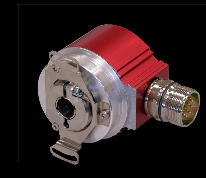
Encoder I__-58(2)
_Optisch, Generation 2
_Magnetische Codescheibe
Explosionsschutzgehäuse: A**58I(2)
Abbildung ähnlich
TR-ECE-BA-DGB-0119 v05 / 03/19/2021
_Zusätzliche Sicherheitshinweise
_Installation
_Inbetriebnahme
_Parametrierung
_Fehlerursachen und Abhilfen
Benutzerhandbuch
Schnittstelle
IE_: 437E00, IO_: 437F00, IP_: 437231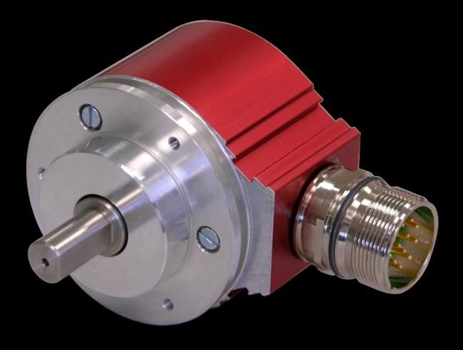
TR-Electronic GmbH
D-78647 Trossingen
Eglishalde 6
Tel.: (0049) 07425/228-0
Fax: (0049) 07425/228-33
E-mail: info@tr-electronic.de
www.tr-electronic.de
Urheberrechtsschutz
Dieses Handbuch, einschließlich den darin enthaltenen Abbildungen, ist
urheberrechtlich geschützt. Drittanwendungen dieses Handbuchs, welche von den
urheberrechtlichen Bestimmungen abweichen, sind verboten. Die Reproduktion,
Übersetzung sowie die elektronische und fotografische Archivierung und
Veränderung bedarf der schriftlichen Genehmigung durch den Hersteller.
Zuwiderhandlungen verpflichten zu Schadenersatz.
Änderungsvorbehalt
Jegliche Änderungen, die dem technischen Fortschritt dienen, vorbehalten.
Dokumenteninformation
Ausgabe-/Rev.-Datum: 03/19/2021
Dokument-/Rev.-Nr.: TR-ECE-BA-DGB-0119 v05
Dateiname: TR-ECE-BA-DGB-0119-05.docx
Verfasser: MÜJ
Schreibweisen
Kursive oder fette Schreibweise steht für den Titel eines Dokuments oder wird zur
Hervorhebung benutzt.
Courier-Schrift zeigt Text an, der auf dem Display bzw. Bildschirm sichtbar ist und
Menüauswahlen von Software.
< > weist auf Tasten der Tastatur Ihres Computers hin (wie etwa ).
TR-Electronic GmbH 2015, All Rights Reserved Printed in the Federal Republic of Germany
Page 2 of 36 TR-ECE-BA-DGB-0119 v05 03/19/2021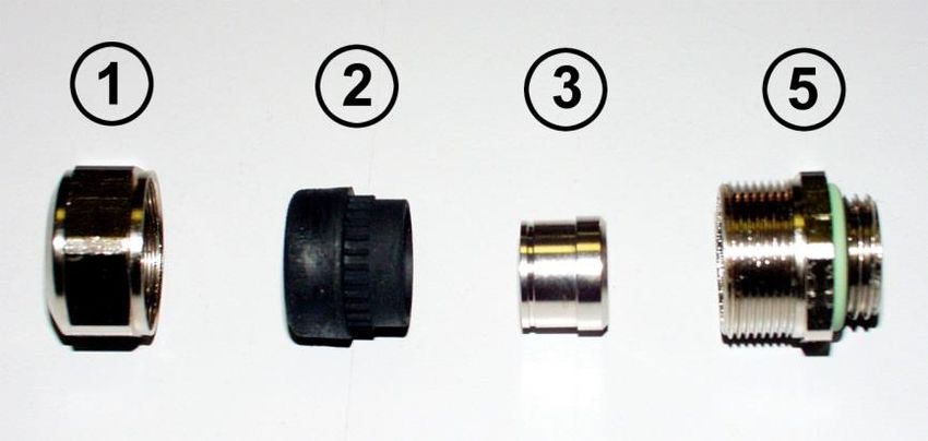
Inhaltsverzeichnis
Inhaltsverzeichnis ............................................................................................................................ 3
Änderungs-Index .............................................................................................................................. 4
1 Allgemeines ................................................................................................................................... 5
1.1 Geltungsbereich ............................................................................................................... 5
1.2 Verwendete Abkürzungen / Begriffe ................................................................................ 6
2 Zusätzliche Sicherheitshinweise ................................................................................................. 7
2.1 Symbol- und Hinweis-Definition ....................................................................................... 7
2.2 Einsatz in explosionsfähigen Atmosphären ..................................................................... 7
3 Maximal zulässige elektrische Drehzahl ..................................................................................... 8
4 Installation / Inbetriebnahme ........................................................................................................ 9
4.1 Anschluss – Hinweise ...................................................................................................... 9
4.2 Kabelspezifikation ............................................................................................................ 9
4.3 Schirmauflage, bei Verwendung von Kabelverschraubungen ........................................ 10
4.4 V/R-Funktion (Zählrichtung – Eingang) ........................................................................... 12
4.5 Schaltausgang Geschwindigkeit ...................................................................................... 12
4.6 Anbindung an den PC (Programmierung) ....................................................................... 14
5 Parametrierung über TRWinProg ................................................................................................ 15
5.1 Geschwindigkeit ............................................................................................................... 15
5.1.1 Geschwindigkeit ............................................................................................... 15
5.1.2 Einheit .............................................................................................................. 15
5.1.3 Überdrehzahl ................................................................................................... 15
5.2 Inkremental ...................................................................................................................... 15
5.2.1 Anzahl Impulse ................................................................................................ 15
5.2.2 Phase ............................................................................................................... 16
5.2.3 Nullimpulsverknüpfung .................................................................................... 16
5.2.4 Set K0 .............................................................................................................. 17
5.2.5 Position ............................................................................................................ 17
5.2.6 Signalpegel ...................................................................................................... 17
6 Fehlerursachen und Abhilfen ....................................................................................................... 18
Printed in the Federal Republic of Germany TR-Electronic GmbH 2015, All Rights Reserved
03/19/2021 TR-ECE-BA-DGB-0119 v05 Page 3 of 36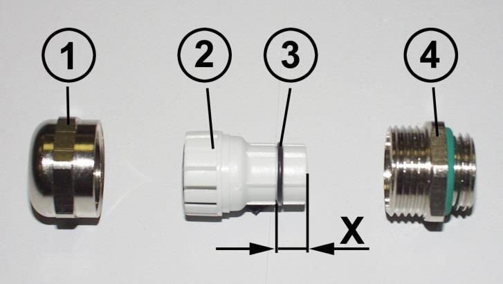
Änderungs-Index Änderungs-Index Änderung Datum Index Erstausgabe 13.10.2015 00 Defaultwert für die Einheit der Geschwindigkeit angepasst 08.02.2017 01 V/R-Beschreibung hinzugefügt 17.07.2017 02 Technische Daten entfernt 11.12.2017 03 IP_58(2) ergänzt 11.07.2018 04 V/R-Funktion optional high- und low-aktiv 19.03.2021 05 TR-Electronic GmbH 2015, All Rights Reserved Printed in the Federal Republic of Germany Page 4 of 36 TR-ECE-BA-DGB-0119 v05 03/19/2021
1 Allgemeines
Das vorliegende schnittstellenspezifische Benutzerhandbuch beinhaltet folgende
Themen:
Ergänzende Sicherheitshinweise zu den bereits in der Montageanleitung
definierten grundlegenden Sicherheitshinweisen
Installation
Inbetriebnahme
Parametrierung
Fehlerursachen und Abhilfen
Da die Dokumentation modular aufgebaut ist, stellt dieses Benutzerhandbuch eine
Ergänzung zu anderen Dokumentationen wie z.B. Produktdatenblätter,
Maßzeichnungen, Prospekte und der Montageanleitung etc. dar.
Das Benutzerhandbuch kann kundenspezifisch im Lieferumfang enthalten sein, oder
kann auch separat angefordert werden.
1.1 Geltungsbereich
Dieses Benutzerhandbuch gilt ausschließlich für Mess-System-Baureihen gemäß
nachfolgendem Typenschlüssel mit Inkremental Schnittstelle:
*1 *2 *3 *4 *5 *6 - *7 *7 *7 *7 *7
Stelle Bezeichnung Beschreibung
A Explosionsschutzgehäuse (ATEX);
*1
I Inkremental-Encoder
E Optische Abtastung ≤ 10000 Impulse/Umdr.
*2 O Optische Abtastung > 10000 Impulse/Umdr.
P Abtastung mit magnetischer Codescheibe
V Vollwelle
S Sacklochwelle
*3 H Hohlwelle
K Kupplung
W Seilzugbox (wire)
*4 58 Außendurchmesser 58 mm
(* 5) I Inkremental-Encoder, nur bei ATEX-Ausführung
*6 2 Generation 2
*7 - Fortlaufende Nummer
* = Platzhalter
Die Produkte sind durch aufgeklebte Typenschilder gekennzeichnet und sind
Bestandteil einer Anlage.
Es gelten somit zusammen folgende Dokumentationen:
siehe Kapitel „Mitgeltende Dokumente“ in der Montageanleitung
www.tr-electronic.de/f/TR-ECE-BA-DGB-0035.
optional: -Benutzerhandbuch
Printed in the Federal Republic of Germany TR-Electronic GmbH 2015, All Rights Reserved
03/19/2021 TR-ECE-BA-DGB-0119 v05 Page 5 of 36Allgemeines
1.2 Verwendete Abkürzungen / Begriffe
EG Europäische Gemeinschaft
EMV Elektro-Magnetische-Verträglichkeit
ESD Elektrostatische Entladung (Electro Static Discharge)
IEC Internationale Elektrotechnische Kommission
NEC National Electrical Code
VDE Verein Deutscher Elektrotechniker
UZS Im Uhrzeigersinn
GUZS Gegen den Uhrzeigersinn
TR-Electronic GmbH 2015, All Rights Reserved Printed in the Federal Republic of Germany
Page 6 of 36 TR-ECE-BA-DGB-0119 v05 03/19/20212 Zusätzliche Sicherheitshinweise
2.1 Symbol- und Hinweis-Definition
bedeutet, dass Tod oder schwere Körperverletzung eintre-
ten kann, wenn die entsprechenden Vorsichtsmaßnahmen
nicht getroffen werden.
bedeutet, dass eine leichte Körperverletzung eintreten kann,
wenn die entsprechenden Vorsichtsmaßnahmen nicht
getroffen werden.
bedeutet, dass ein Sachschaden eintreten kann, wenn die
entsprechenden Vorsichtsmaßnahmen nicht getroffen
werden.
bezeichnet wichtige Informationen bzw. Merkmale und
Anwendungstipps des verwendeten Produkts.
2.2 Einsatz in explosionsfähigen Atmosphären
Für den Einsatz in explosionsfähigen Atmosphären wird das Standard Mess-System
je nach Anforderung in ein entsprechendes Explosionsschutzgehäuse eingebaut.
Die Produkte sind auf dem Typenschild mit einer zusätzlichen -Kennzeichnung
gekennzeichnet.
Die „Bestimmungsgemäße Verwendung“, sowie alle Informationen für den
gefahrlosen Einsatz des ATEX-konformen Mess-Systems in explosionsfähigen
Atmosphären sind im -Benutzerhandbuch enthalten, welches der Lieferung
beigelegt wird.
Das in das Explosionsschutzgehäuse eingebaute Standard Mess-System kann somit
in explosionsfähigen Atmosphären eingesetzt werden.
Durch den Einbau in das Explosionsschutzgehäuse bzw. durch die
Explosionsschutzanforderungen, ergeben sich Veränderungen an den ursprünglichen
Eigenschaften des Mess-Systems.
Anhand der Vorgaben im -Benutzerhandbuch ist zu überprüfen, ob die dort
definierten Eigenschaften den applikationsspezifischen Anforderungen genügen.
Der gefahrlose Einsatz erfordert zusätzliche Maßnahmen bzw. Anforderungen. Diese
sind vor der Erstinbetriebnahme zu erfassen und müssen entsprechend umgesetzt
werden.
Printed in the Federal Republic of Germany TR-Electronic GmbH 2015, All Rights Reserved
03/19/2021 TR-ECE-BA-DGB-0119 v05 Page 7 of 36Maximal zulässige elektrische Drehzahl
3 Maximal zulässige elektrische Drehzahl
Die elektrische Maximaldrehzahl ist unabhängig von der mechanischen
Maximaldrehzahl und ist eine Funktion der programmierten Impulse pro Umdrehung.
Bei Überschreiten der elektrischen Maximaldrehzahl wird dies mit Setzen des
Schaltausgangs „Geschwindigkeit“ angezeigt, siehe Seite 12.
Wird die maximal zulässige elektrische Drehzahl überschritten, werden
vom Mess-System keine gültigen Messwerte mehr ausgegeben!
Der Schaltausgang „Geschwindigkeit“ des Mess-Systems ist vom
Betreiber zwingend mit in das eigene Sicherheitskonzept einzubinden.
Bei Setzen des Schaltausgangs, durch Überschreiten der elektrischen
Maximaldrehzahl, ist die Anlage in einen sicheren Zustand zu überführen.
TR-Electronic GmbH 2015, All Rights Reserved Printed in the Federal Republic of Germany
Page 8 of 36 TR-ECE-BA-DGB-0119 v05 03/19/20214 Installation / Inbetriebnahme
4.1 Anschluss – Hinweise
Die elektrischen Ausstattungsmerkmale werden hauptsächlich durch die variable
Anschluss-Technik vorgegeben.
Ob das Mess-System
externe Eingänge
externe Ausgänge
einen Nullimpuls oder invertierte Signalfolgen bei der Inkrementalschnittstelle
unterstützt, wird deshalb durch die gerätespezifische Steckerbelegung definiert.
Der Anschluss kann nur in Verbindung mit der gerätespezifischen Steckerbelegung
vorgenommen werden!
Bei der Auslieferung des Mess-Systems wird jeweils eine Steckerbelegung in gedruckter
Form beigelegt und sie kann nachträglich auch von der Seite
„www.tr-electronic.de/service/downloads/steckerbelegungen.html?L=0“ heruntergeladen
werden. Die Steckerbelegungsnummer ist auf dem Typenschild des Mess-Systems
vermerkt.
4.2 Kabelspezifikation
Signal Empfehlung
2
min. 0,5 mm , paarig verseilt und geschirmt
Spannungsabfall an den Zuleitungen beachten!
Insbesondere beim 5 VDC-Betrieb ist darauf zu achten, dass
Versorgung am Mess-System der untere Grenzwert von 4,75 VDC nicht
unterschritten wird. Um die Spannungsverluste an den
Zuleitungen zu kompensieren, wird der Einsatz von Netzteilen
mit „Sense-Funktion“ empfohlen.
K1+ / K1–
2
K2+ / K2– min. 0,25 mm , jeweils paarig verseilt und geschirmt
K0+ / K0–
2 2
Ein-/Ausgänge 0,14 mm ... 0,25 mm
Um eine hohe Störfestigkeit des Systems gegen elektromagnetische Störstrahlungen
zu erzielen, müssen geschirmte Leitungen verwendet werden. Der Schirm sollte
möglichst beidseitig und gut leitend über großflächige Schirmschellen an
Schutzerde angeschlossen werden. Nur wenn die Maschinenerde gegenüber der
Schaltschrankerde stark mit Störungen behaftet ist, sollte man den Schirm einseitig
im Schaltschrank erden.
Weiterhin ist zu beachten, dass die Datenleitungen möglichst separat von allen
starkstromführenden Kabeln verlegt werden.
Um einen sicheren und störungsfreien Betrieb zu gewährleisten, sind die einschlägigen
Normen und Richtlinien zu beachten!
Insbesondere sind die EMV-Richtlinie sowie die Schirmungs- und Erdungsrichtlinien in
den jeweils gültigen Fassungen zu beachten!
Printed in the Federal Republic of Germany TR-Electronic GmbH 2015, All Rights Reserved
03/19/2021 TR-ECE-BA-DGB-0119 v05 Page 9 of 36Installation / Inbetriebnahme
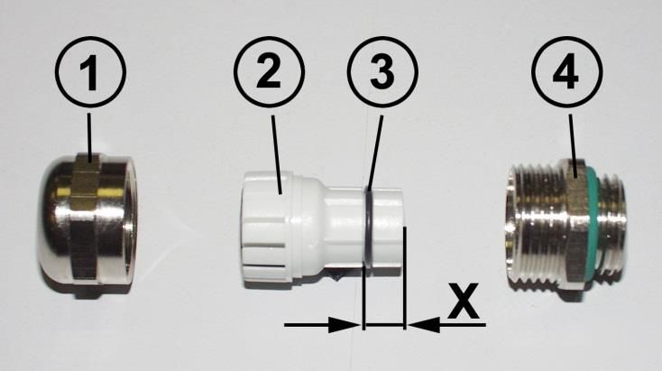
4.3 Schirmauflage, bei Verwendung von Kabelverschraubungen
Die Schirmauflage erfolgt durch spezielle EMV-gerechte Kabelverschraubungen, bei
denen die Kabelschirmung innen aufgelegt werden kann.
Montage für Kabelverschraubung, Variante A
Pos. 1 Überwurfmutter
Pos. 2 Dichteinsatz
Pos. 3 Kontakthülse
Pos. 5 Einschraubstutzen
1. Schirmumflechtung / Schirmfolie auf Maß „X“ zurückschneiden.
2. Überwurfmutter (1) und Dichteinsatz / Kontakthülse (2) + (3) auf das Kabel
aufschieben.
3. Die Schirmumflechtung / Schirmfolie um ca. 90° umbiegen (4).
4. Dichteinsatz / Kontakthülse (2) + (3) bis an die Schirmumflechtung /
Schirmfolie schieben.
5. Einschraubstutzen (5) am Gehäuse montieren.
6. Dichteinsatz / Kontakthülse (2) + (3) in Einschraubstutzen (5) bündig
zusammen stecken.
7. Überwurfmutter (1) mit Einschraubstutzen (5) verschrauben.
TR-Electronic GmbH 2015, All Rights Reserved Printed in the Federal Republic of Germany
Page 10 of 36 TR-ECE-BA-DGB-0119 v05 03/19/2021Montage für Kabelverschraubung, Variante B
Pos. 1 Überwurfmutter
Pos. 2 Klemmeinsatz
Pos. 3 innerer O-Ring
Pos. 4 Einschraubstutzen
1. Schirmumflechtung / Schirmfolie auf Maß „X“ + 2 mm zurückschneiden.
2. Überwurfmutter (1) und Klemmeneinsatz (2) auf das Kabel aufschieben.
3. Die Schirmumflechtung / Schirmfolie um ca. 90° umbiegen.
4. Klemmeinsatz (2) bis an die Schirmumflechtung / Schirmfolie schieben und
das Geflecht um den Klemmeinsatz (2) zurückstülpen, so dass das Geflecht
über den inneren O-Ring (3) geht, und nicht über dem zylindrischen Teil oder
den Verdrehungsstegen liegt.
5. Einschraubstutzen (4) am Gehäuse montieren.
6. Klemmeinsatz (2) in Einschraubstutzen (4) einführen, so dass die
Verdrehungsstege in die im Einschraubstutzen (4) vorgesehenen
Längsnuten passen.
7. Überwurfmutter (1) mit Einschraubstutzen (4) verschrauben.
1
2
3
4
Printed in the Federal Republic of Germany TR-Electronic GmbH 2015, All Rights Reserved
03/19/2021 TR-ECE-BA-DGB-0119 v05 Page 11 of 36Installation / Inbetriebnahme
4.4 V/R-Funktion (Zählrichtung – Eingang)
Das Mess-System ist gerätespezifisch mit einem V/R-Eingang am Gerätestecker
ausgestattet. Je nach Mess-System-Option kann die V/R-Funktion entweder mit
einem High- oder einem Low-Pegel ausgelöst werden.
Option „V/R high-aktiv“:
Durch Beschalten des externen Eingangs mit Versorgungsspannung (US) wird die
momentan eingestellte Zählrichtung invertiert. Damit ändert sich ebenfalls das
Vorzeichen der Mess-System-Geschwindigkeit.
Option „V/R low-aktiv“:
Durch Beschalten des externen Eingangs mit Ground (GND) wird die momentan
eingestellte Zählrichtung invertiert. Damit ändert sich ebenfalls das Vorzeichen der
Mess-System-Geschwindigkeit.
Eingang Beschreibung Default
1)
nicht beschaltet Mess-System-Position im Uhrzeigersinn steigend X
1)
beschaltet Mess-System-Position im Uhrzeigersinn fallend
1)
mit Blick auf Anflanschung
4.5 Schaltausgang Geschwindigkeit
Die Art des Schaltausgangs Geschwindigkeit ist abhängig von der Abtast-Variante des
Mess-Systems. Mess-Systeme mit optischer Abtastung sind mit einem
kurzschlussfesten Open-Collector – Schaltausgang und Mess-Systeme mit
magnetischer Codescheibe mit einem Push/Pull – Schaltausgang ausgestattet.
Die Schaltschwelle des Schaltausgangs wird über den Parameter Überdrehzahl
eingestellt, siehe Seite 15.
Prinzip Ausgangs-Schaltbild „Open Collector“ (optische Abtastung):
Der externe Vorwiderstand Rext muss so gewählt werden, dass der Maximal-Strom
von 35 mA nicht überschritten wird.
TR-Electronic GmbH 2015, All Rights Reserved Printed in the Federal Republic of Germany
Page 12 of 36 TR-ECE-BA-DGB-0119 v05 03/19/2021Prinzip Ausgangs-Schaltbild „Push/Pull“ (Abtastung mit magnetischer Code-
scheibe IP_58_):
Printed in the Federal Republic of Germany TR-Electronic GmbH 2015, All Rights Reserved
03/19/2021 TR-ECE-BA-DGB-0119 v05 Page 13 of 36Installation / Inbetriebnahme
4.6 Anbindung an den PC (Programmierung)
Was wird von TR-Electronic benötigt?
Schaltschrankmodul Art.-Nr.: 490-00101
Programmier-Set Art.-Nr.: 490-00310:
Kunststoff-Koffer,
mit nachfolgenden Komponenten:
– USB PC-Adapter V4
Umsetzung USB RS485
– USB-Kabel 1,00 m
Verbindungskabel zwischen
PC-Adapter und PC
– Flachbandkabel 1,30 m
Verbindungskabel zwischen
PC-Adapter und TR-Schaltschrank-Modul
(15-pol. SUB-D Buchse/Stecker)
– Steckernetzteil 24 V DC, 1A
Versorgungsmöglichkeit des angeschlossenen Gerätes
über den PC-Adapter
– Software- und Support-DVD
- USB-Treiber, Soft-Nr.: 490-00421
- TRWinProg, Soft-Nr.: 490-00416
- EPROGW32, Soft-Nr.: 490-00418
- LTProg, Soft-Nr.: 490-00415
– Installationsanleitung
TR-E-TI-DGB-0074, Deutsch/Englisch
Für den Betrieb ab Windows 7 wird der USB PC-Adapter HID V5,
Art-Nr.: 490-00313 / 490-00314 mit Installationsanleitung TR-E-TI-DGB-0103 benötigt.
TR-Electronic GmbH 2015, All Rights Reserved Printed in the Federal Republic of Germany
Page 14 of 36 TR-ECE-BA-DGB-0119 v05 03/19/20215 Parametrierung über TRWinProg
Um die Parametrierung ändern zu können, muss die TRWinProg-
Programmierschnittstelle auf dem Mess-System Stecker aufgelegt sein. Ist dies nicht
der Fall, sind die nachfolgenden Parameter kundenspezifisch werksseitig festgelegt.
5.1 Geschwindigkeit
5.1.1 Geschwindigkeit
Im Onlinezustand wird im Feld Geschwindigkeit die aktuelle Mess-System-
Drehzahl als Betragswert in der unter Parameter Einheit eingestellten Einheit
angezeigt. Bei aktivierter V/R-Funktion (siehe Kap.: 4.4) ist das Vorzeichen der
Geschwindigkeit invertiert.
5.1.2 Einheit
Auswahl Beschreibung Default
Ausgabe der Geschwindigkeit in
U/s
Umdrehungen pro Sekunde
Ausgabe der Geschwindigkeit in
U/min X
Umdrehungen pro Minute
Ausgabe der Geschwindigkeit in
U/h
Umdrehungen pro Stunde
5.1.3 Überdrehzahl
-1
Eingabe der Schaltschwelle [min ] für den Schaltausgang „Geschwindigkeit“, siehe
Seite 12. Schaltausgang = aktiv, wenn Drehzahl > Schaltschwelle.
Die Schaltschwelle muss sich innerhalb der elektrischen Maximaldrehzahl befinden.
Das Mess-System überprüft die parametrierte Überdrehzahl und verwirft die Eingabe,
wenn die elektrische Maximaldrehzahl überschritten wird. Siehe auch Kapitel
„Maximal zulässige elektrische Drehzahl“ auf Seite 8.
5.2 Inkremental
5.2.1 Anzahl Impulse
Festlegung der ausgegebenen Impulse/Umdrehung.
Untergrenze 2
Obergrenze IE_ 10000
Obergrenze IO_ 65536
Obergrenze IP_ 10000
Programmierbarkeit einschrittig
Printed in the Federal Republic of Germany TR-Electronic GmbH 2015, All Rights Reserved
03/19/2021 TR-ECE-BA-DGB-0119 v05 Page 15 of 36Parametrierung über TRWinProg
5.2.2 Phase
Auswahl Beschreibung Bedingungen Default
K1 voreilend
X
(Zählrichtung steigend)
K1 nacheilend
(Zählrichtung fallend)
5.2.3 Nullimpulsverknüpfung
Auswahl Beschreibung Bedingungen Default
Länge: 180°
X
Lage: K1 = 0
Länge: 90°
Lage: K1 & K2 = 0 Parameter:
Zählrichtung
steigend
Länge: 90°
Lage: K1 & K2 = 1
Länge: 180°
Lage: K1 = 1
TR-Electronic GmbH 2015, All Rights Reserved Printed in the Federal Republic of Germany
Page 16 of 36 TR-ECE-BA-DGB-0119 v05 03/19/20215.2.4 Set K0
Gefahr von Körperverletzung und Sachschaden durch einen
Istwertsprung bei Ausführung der Set K0-Justage-Funktion!
Die Set K0-Justage-Funktion sollte nur im Mess-System-Stillstand
ausgeführt werden, bzw. muss der resultierende Istwertsprung
programmtechnisch und anwendungstechnisch erlaubt sein!
Diese Funktion ist in der Variante mit magnetischer Codescheibe IP_58_ nicht
verfügbar.
Die Set K0-Justage-Funktion kann nur ausgeführt werden, wenn das Eingangssignal
>50 ms statisch am Eingang anliegt. Nach ca. 0,5 s wird das Nullimpuls-Signal am
Ausgang gesetzt.
Wird der Preset-Eingang nicht benötigt, sollte er zur Störunterdrückung gesperrt
werden.
Auswahl Beschreibung Default
freigegeben Set K0-Justage-Funktion aktiv
gesperrt Set K0-Justage-Funktion inaktiv X
5.2.5 Position
Im Onlinezustand wird im Feld Position die aktuelle Mess-System-Position in
Schritten angezeigt.
Resultierende Impulse = Anzahl Schritte/4
Gefahr von Körperverletzung und Sachschaden durch einen
Istwertsprung bei Ausführung der Justage-Funktion!
Die Justage-Funktion sollte nur im Mess-System-Stillstand ausgeführt
werden, bzw. muss der resultierende Istwertsprung programmtechnisch
und anwendungstechnisch erlaubt sein!
Durch Eingabe eines Wertes in das Feld Position kann das Mess-System auf den
gewünschten Positionswert justiert werden. Der Wert wird mit Ausführung der
Funktion Daten zum Gerät schreiben übernommen.
Untergrenze 0
Obergrenze (programmierte Anzahl Impulse/Umdrehung * 4) – 1
5.2.6 Signalpegel
Auswahl Beschreibung
Ausgangstreiber: Gegentakt-Ausgangsstufe
Versorgungsspannung Pegel = Versorgungsspannung
Die Versorgungsspannung muss > 8 VDC betragen.
Ausgangstreiber: RS422-Ausgangsstufe
TTL
Pegel = 5 VDC
Printed in the Federal Republic of Germany TR-Electronic GmbH 2015, All Rights Reserved
03/19/2021 TR-ECE-BA-DGB-0119 v05 Page 17 of 36Fehlerursachen und Abhilfen
6 Fehlerursachen und Abhilfen
Störung Ursache Abhilfe
Vibrationen, Schläge und Stöße werden mit so genannten
„Schockmodulen“ gedämpft. Wenn der Fehler trotz dieser
starke Vibrationen
Maßnahme wiederholt auftritt, muss das Mess-System
getauscht werden.
Elektrische
Störungen Gegen elektrische Störungen helfen eventuell isolierende
Positionssprünge
Flansche und Kupplungen aus Kunststoff, sowie
des Mess-Systems
geschirmte Kabel.
EMV
Übermäßige axiale
Kupplungen vermeiden mechanische Belastungen der
und radiale Belastung
Welle. Wenn der Fehler trotz dieser Maßnahme weiterhin
der Welle oder einen
auftritt, muss das Mess-System getauscht werden.
Defekt der Abtastung.
TR-Electronic GmbH 2015, All Rights Reserved Printed in the Federal Republic of Germany
Page 18 of 36 TR-ECE-BA-DGB-0119 v05 03/19/2021INCREMENTAL
Encoder I__-58(2)
_Optical, Generation 2
_Magnetic code disc
Explosion Protection Enclosure: A**58I(2)
Stock photo
_Additional safety instructions
_Installation
_Commissioning
_Parameterization User Manual
_Cause of faults and remedies Interface
Printed in the Federal Republic of Germany TR-Electronic GmbH 2015, All Rights Reserved
03/19/2021 TR-ECE-BA-DGB-0119 v05 Page 19 of 36TR-Electronic GmbH
D-78647 Trossingen
Eglishalde 6
Tel.: (0049) 07425/228-0
Fax: (0049) 07425/228-33
E-mail: info@tr-electronic.de
www.tr-electronic.de
Copyright protection
This Manual, including the illustrations contained therein, is subject to copyright
protection. Use of this Manual by third parties in contravention of copyright
regulations is forbidden. Reproduction, translation as well as electronic and
photographic archiving and modification require the written content of the
manufacturer. Offenders will be liable for damages.
Subject to amendments
Any technical changes that serve the purpose of technical progress, reserved.
Document information
Release date/Rev. date: 03/19/2021
Document rev. no.: TR-ECE-BA-DGB-0119 v05
File name: TR-ECE-BA-DGB-0119-05.docx
Author: MÜJ
Font styles
Italic or bold font styles are used for the title of a document or are used for
highlighting.
Courier font displays text, which is visible on the display or screen and software
menu selections.
< > indicates keys on your computer keyboard (such as ).
TR-Electronic GmbH 2015, All Rights Reserved Printed in the Federal Republic of Germany
Page 20 of 36 TR-ECE-BA-DGB-0119 v05 03/19/2021Contents
Contents ............................................................................................................................................ 21
Revision index .................................................................................................................................. 22
1 General information ...................................................................................................................... 23
1.1 Applicability ...................................................................................................................... 23
1.2 Abbreviations and definitions ........................................................................................... 24
2 Additional safety instructions ...................................................................................................... 25
2.1 Definition of symbols and instructions ............................................................................. 25
2.2 Usage in explosive atmospheres ..................................................................................... 25
3 Max. permissible electrical speed ............................................................................................... 26
4 Installation / Commissioning ....................................................................................................... 27
4.1 Connection – notes .......................................................................................................... 27
4.2 Cable definition ................................................................................................................ 27
4.3 Shield cover, when using cable screw glands ................................................................. 28
4.4 F/B function (Counting direction – input) ......................................................................... 30
4.5 Switching output speed ................................................................................................... 30
4.6 Connection to the PC (programming) .............................................................................. 32
5 Parameterization via TRWinProg ................................................................................................. 33
5.1 Velocity ............................................................................................................................ 33
5.1.1 Velocity ............................................................................................................ 33
5.1.2 Unit ................................................................................................................... 33
5.1.3 Overspeed ....................................................................................................... 33
5.2 Incremental ...................................................................................................................... 33
5.2.1 Number of impulses ......................................................................................... 33
5.2.2 Phase ............................................................................................................... 34
5.2.3 Zero pulse logic operation ............................................................................... 34
5.2.4 Set K0 .............................................................................................................. 35
5.2.5 Position ............................................................................................................ 35
5.2.6 Signal level....................................................................................................... 35
6 Causes of faults and remedies .................................................................................................... 36
Printed in the Federal Republic of Germany TR-Electronic GmbH 2015, All Rights Reserved
03/19/2021 TR-ECE-BA-DGB-0119 v05 Page 21 of 36Revision index Revision index Revision Date Index First release 10/13/2015 00 Default value for the unit of speed adjusted 02/08/2017 01 F/B function description added (counting direction) 07/17/2017 02 Technical data removed 12/11/2017 03 IP_58(2) added 07/11/2018 04 F/B function optionally high- and low-active 03/19/2021 05 TR-Electronic GmbH 2015, All Rights Reserved Printed in the Federal Republic of Germany Page 22 of 36 TR-ECE-BA-DGB-0119 v05 03/19/2021
1 General information
The interface specific User Manual includes the following topics:
Safety instructions in additional to the basic safety instructions defined in the
Assembly Instructions
Installation
Commissioning
Parameterization
Causes of faults and remedies
As the documentation is arranged in a modular structure, this User Manual is
supplementary to other documentation, such as product datasheets, dimensional
drawings, leaflets and the assembly instructions etc.
The User Manual may be included in the customer’s specific delivery package or it
may be requested separately.
1.1 Applicability
This User Manual applies exclusively to measuring system models according to the
following type designation code with Incremental interface:
*1 *2 *3 *4 *5 *6 - *7 *7 *7 *7 *7
Position Notation Description
A Explosion protection enclosure (ATEX);
*1
I Incremental-Encoder
E Optical scanning unit ≤ 10000 impulses/rev.
*2 O Optical scanning unit > 10000 impulses/rev.
P Scanning unit with magnetic code disc
V Solid shaft
S Blind shaft
*3 H Hollow through shaft
K Coupling
W Rope length transmitter (wire)
*4 58 External diameter 58 mm
(* 5) I Incremental-Encoder, ATEX only
*6 2 Generation 2
*7 - Consecutive number
* = wildcard
The products are labelled with affixed nameplates and are components of a system.
The following documentation therefore also applies:
see chapter “Other applicable documents” in the Assembly Instructions:
www.tr-electronic.de/f/TR-ECE-BA-DGB-0035.
optional: -User Manual
Printed in the Federal Republic of Germany TR-Electronic GmbH 2015, All Rights Reserved
03/19/2021 TR-ECE-BA-DGB-0119 v05 Page 23 of 36General information
1.2 Abbreviations and definitions
EC European Community
EMC Electro Magnetic Compatibility
ESD Electro Static Discharge
IEC International Electrotechnical Commission
NEC National Electrical Code
VDE German Electrotechnicians Association
CW Clockwise
CCW Counterclockwise
TR-Electronic GmbH 2015, All Rights Reserved Printed in the Federal Republic of Germany
Page 24 of 36 TR-ECE-BA-DGB-0119 v05 03/19/20212 Additional safety instructions
2.1 Definition of symbols and instructions
means that death or serious injury can occur if the required
precautions are not met.
means that minor injuries can occur if the required
precautions are not met.
means that damage to property can occur if the required
precautions are not met.
indicates important information or features and application
tips for the product used.
2.2 Usage in explosive atmospheres
When used in explosive atmospheres, the standard measuring system has to be
installed in an appropriate explosion protective enclosure and subject to requirements.
The products are labeled with an additional marking on the nameplate:
The “intended use” as well as any information on the safe usage of the ATEX-
compliant measuring system in explosive atmospheres are contained in the User
Manual which is enclosed when the device is delivered.
Standard measuring systems that are installed in the explosion protection enclosure
can therefore be used in explosive atmospheres.
When the measuring system is installed in the explosion protection enclosure, which
means that it meets explosion protection requirements, the properties of the
measuring system will no longer be as they were originally.
Following the specifications in the User Manual, please check whether the
properties defined in that manual meet the application-specific requirements.
Fail-safe usage requires additional measures and requirements. Such measures and
requirements must be determined prior to initial commissioning and must be taken and
met accordingly.
Printed in the Federal Republic of Germany TR-Electronic GmbH 2015, All Rights Reserved
03/19/2021 TR-ECE-BA-DGB-0119 v05 Page 25 of 36Max. permissible electrical speed
3 Max. permissible electrical speed
The electrical maximum speed is independent of the mechanical maximum speed and
is a function of the programmed Pulses per Revolution.
When exceeding the electrical maximum speed this is reported with setting the
switching output "Speed" to high-level, see page 30.
If the electrical maximum speed is exceeded, by the measuring system no
more valid measured values are output!
It is mandatory for the operator to integrate the switching output “Speed”
of the measuring system into his own safety concept.
If the switching output is set to high-level, because the electrical
maximum speed was exceeded, the system must be put into a safe state.
TR-Electronic GmbH 2015, All Rights Reserved Printed in the Federal Republic of Germany
Page 26 of 36 TR-ECE-BA-DGB-0119 v05 03/19/20214 Installation / Commissioning
4.1 Connection – notes
Mainly, the electrical characteristics are defined by the variable connection technique.
Whether the measuring system supports
external inputs
external outputs
a reference pulse or inverted signal sequences of the incremental interface
is therefore defined by the device specific pin assignment.
The connection can be made only in connection with the device specific pin
assignment!
At the delivery of the measuring system one device specific pin assignment in printed
form is enclosed and it can be downloaded afterwards from the page
„www.tr-electronic.com/service/downloads/pin-assignments.html”. The number of the
pin assignment is noted on the nameplate of the measuring system.
4.2 Cable definition
Signal Recommendation
2
min. 0,5 mm , twisted in pairs and shielded
Consider voltage drops at the supply cables!
Especially in the 5 VDC operation it must be ensured that the
Supply voltage limiting value of 4.75 VDC at the measuring system is not fallen
below. In order to compensate the voltage losses at the supply
cables, the usage of power packs with "Sense function" is
recommended.
K1+ / K1–
2
K2+ / K2– min. 0.25 mm , each twisted in pairs and shielded
K0+ / K0–
2 2
Input / Output 0.14 mm ... 0.25 mm
Shielded cables must be used to achieve high electromagnetic interference stability.
The shielding should be connected with low resistance to protective ground using
large shield clips at both ends. Only if the machine ground is heavily contaminated
with interference towards the control cabinet ground the shield should be grounded in
the control cabinet only.
It is also important that the data-lines are routed separate from power current carrying
cables if at all possible.
The applicable standards and guidelines are to be observed to insure safe and stable
operation!
In particular, the applicable EMC directive and the shielding and grounding guidelines
must be observed!
Printed in the Federal Republic of Germany TR-Electronic GmbH 2015, All Rights Reserved
03/19/2021 TR-ECE-BA-DGB-0119 v05 Page 27 of 36Installation / Commissioning
4.3 Shield cover, when using cable screw glands
The shield cover is connected with a special EMC cable gland, whereby the cable
shielding is fitted on the inside.
Cable gland assembly, variant A
Pos. 1 Nut
Pos. 2 Seal
Pos. 3 Contact bush
Pos. 5 Screw socket
1. Cut shield braid / shield foil back to dimension "X".
2. Slide the nut (1) and seal / contact bush (2) + (3) over the cable.
3. Bend the shield braining / shield foil to 90° (4).
4. Slide seal / contact bush (2) + (3) up to the shield braining / shield foil.
5. Assemble screw socket (5) on the housing.
6. Push seal / contact bush (2) + (3) flush into the screw socket (5).
7. Screw the nut (1) to the screw socket (5).
TR-Electronic GmbH 2015, All Rights Reserved Printed in the Federal Republic of Germany
Page 28 of 36 TR-ECE-BA-DGB-0119 v05 03/19/2021Cable gland assembly, variant B
Pos. 1 Nut
Pos. 2 Clamping ring
Pos. 3 Inner O-ring
Pos. 4 Screw socket
1. Cut shield braid / shield foil back to dimension "X" + 2 mm.
2. Slide the nut (1) and clamping ring (2) over the cable.
3. Bend the shield braining / shield foil to approx. 90°.
4. Push clamping ring (2) up to the shield braid / shield foil and wrap the braiding
back around the clamping ring (2), such that the braiding goes around the
inner O-ring (3), and is not above the cylindrical part or the torque supports.
5. Assemble screw socket (4) on the housing.
6. Insert the clamping ring (2) in the screw socket (4) such that the torque
supports fit in the slots in the screw socket (4).
7. Screw the nut (1) to the screw socket (4).
1
2
3
4
Printed in the Federal Republic of Germany TR-Electronic GmbH 2015, All Rights Reserved
03/19/2021 TR-ECE-BA-DGB-0119 v05 Page 29 of 36Installation / Commissioning
4.4 F/B function (Counting direction – input)
The measuring system is equipped device specific with an F/B input on the device
connector. Depending on the measuring system option, the F/B function can be
triggered with either a high or a low level.
Option "F/B high-active":
By connecting the external input with supply voltage (US), the currently set counting
direction is inverted. This also changes the sign of the measuring system velocity.
Option "F/B low-active":
By connecting the external input with ground (GND), the currently set counting
direction is inverted. This also changes the sign of the measuring system velocity.
Input Description Default
1)
not connected Measuring system position increasing clockwise X
1)
connected Measuring system position decreasing clockwise
1)
with view onto the flange connection
4.5 Switching output speed
The type of the “Switching output speed” depends on the type of the scanning unit of
the measuring system. Measuring systems with optical scanning units are equipped
with a short-circuit proof open-collector switching output and measuring systems with
magnetic code disc scanning units are equipped with a Push/Pull switching output.
The switching threshold of the switching output can be adjusted via the parameter
Overspeed, see page 33.
Schematic output circuit diagram „Open Collector“ (optical scanning unit):
The external pre-resistor Rext must be selected in such a way that the maximum
current of 35 mA is not exceeded.
TR-Electronic GmbH 2015, All Rights Reserved Printed in the Federal Republic of Germany
Page 30 of 36 TR-ECE-BA-DGB-0119 v05 03/19/2021Schematic output circuit diagram „Push/Pull“ (scanning unit with magnetic
code disc IP_58_):
Printed in the Federal Republic of Germany TR-Electronic GmbH 2015, All Rights Reserved
03/19/2021 TR-ECE-BA-DGB-0119 v05 Page 31 of 36Installation / Commissioning
4.6 Connection to the PC (programming)
What will be needed by TR-Electronic?
Switch cabinet module Order-No.: 490-00101
Programming set Order-No.: 490-00310:
Plastic case,
with the following components:
– USB PC adapter V4
Conversion USB RS485
– USB cable 1.00 m
Connection cable between
PC adapter and PC
– Flat ribbon cable 1.30 m
Connection cable between
PC adapter and TR switch cabinet module
(15-pol. SUB-D female/male)
– Plug Power Supply Unit 24 V DC, 1A
The connected device can be supplied via the PC adapter
– Software- and Support-DVD
- USB driver, Soft-No.: 490-00421
- TRWinProg, Soft-No.: 490-00416
- EPROGW32, Soft-No.: 490-00418
- LTProg, Soft-No.: 490-00415
– Installation Guide
TR-E-TI-DGB-0074, German/English
For operation ex Windows 7 the USB PC adapter HID V5, order no.: 490-00313 /
490-00314 with installation guide TR-E-TI-DGB-0103 must be used.
TR-Electronic GmbH 2015, All Rights Reserved Printed in the Federal Republic of Germany
Page 32 of 36 TR-ECE-BA-DGB-0119 v05 03/19/20215 Parameterization via TRWinProg
In order to be able to change the parameterization, the TRWinProg programming
interface must be connected to the measuring system connector. If this is not the
case, the following parameters are firmly set to the customer specification.
5.1 Velocity
5.1.1 Velocity
In the online state in the field Velocity the current measuring system speed is
displayed. The value is output without sign and in the unit which is adjusted under the
parameter Unit. If the F/B function is active (see chapter: 4.4), the sign of the velocity
is inverted.
5.1.2 Unit
Selection Description Default
U/s Output of the Velocity in revolutions per second
U/min Output of the Velocity in revolutions per minute X
U/h Output of the Velocity in revolutions per hour
5.1.3 Overspeed
-1
Input of the switching threshold [min ] for the switching output “Speed”, see page 30.
Switching output = active, if the speed > switching threshold.
The switching threshold must be within the electrical maximum speed.
The measuring system checks the programmed overspeed and aborts the input, if the
electrical maximum speed is exceeded. See also chapter “Max. permissible electrical
speed” on page 26.
5.2 Incremental
5.2.1 Number of impulses
Specification of the output pulses per revolution.
Lower limit 2
Upper limit IE_ 10000
Upper limit IO_ 65536
Upper limit IP_ 10000
Programmability 1-step
Printed in the Federal Republic of Germany TR-Electronic GmbH 2015, All Rights Reserved
03/19/2021 TR-ECE-BA-DGB-0119 v05 Page 33 of 36Parameterization via TRWinProg
5.2.2 Phase
Selection Description Conditions Default
K1, leading signal
(counting direction X
increasing)
K1, lagging signal
(counting direction
decreasing)
5.2.3 Zero pulse logic operation
Selection Description Conditions Default
Length: 180°
X
Position: K1 = 0
Length: 90°
Position K1 & K2 = 0 Parameter:
Count direction
increasing
Length: 90°
Position: K1 & K2 = 1
Length: 180°
Position: K1 = 1
TR-Electronic GmbH 2015, All Rights Reserved Printed in the Federal Republic of Germany
Page 34 of 36 TR-ECE-BA-DGB-0119 v05 03/19/20215.2.4 Set K0
Risk of injury and damage to property by an actual value jump when the
Set K0 adjustment function is performed!
The Set K0 function should only be performed when the measuring system
is at rest, otherwise the resulting actual value jump must be permitted in
the program and application!
This function is not available in the magnetic code disc variant IP_58_.
The Set K0 function only can be executed if the input signal is present statically for
>50 ms at the input. After approx. 0.5 s the zero pulse signal at the output is set. If the
Set K0 function input is not used, he should be disabled to suppress interference.
Selection Description Default
In use Set K0 function active
Not in use Set K0 function inactive X
5.2.5 Position
In the online state in the field Position the current measuring system position in
steps is displayed.
Resultant impulses = Number of steps/4
Risk of injury and damage to property by an actual value jump when the
adjustment function is performed!
The adjustment function should only be performed when the measuring
system is at rest, otherwise the resulting actual value jump must be
permitted in the program and application!
With entering of a value into the field Position the measuring system can be
adjusted on the desired position value. The new position is set if the function Data
write to device is executed.
Lower limit 0
Upper limit (programmed number of impulses/revolution * 4) – 1
5.2.6 Signal level
Selection Description
Output driver: Push-Pull; Level = Supply voltage
Supply voltage
The supply voltage must be > 8 VDC
TTL Output driver: RS422; Level = 5 VDC
Printed in the Federal Republic of Germany TR-Electronic GmbH 2015, All Rights Reserved
03/19/2021 TR-ECE-BA-DGB-0119 v05 Page 35 of 36Causes of faults and remedies
6 Causes of faults and remedies
Fault Cause Remedy
Vibrations, impacts and shocks are dampened with "shock
Strong vibrations modules". If the error recurs despite this measure, the
measuring system must be replaced.
Electrical faults
Position skips Perhaps isolated flanges and couplings made of plastic
of the measuring help against electrical faults, as well as shielded cables.
system EMC
Extreme axial and
Couplings prevent mechanical stress on the shaft. If the
radial load on the
error still occurs despite this measure, the measuring
shaft may result in a
system must be replaced.
scanning defect.
TR-Electronic GmbH 2015, All Rights Reserved Printed in the Federal Republic of Germany
Page 36 of 36 TR-ECE-BA-DGB-0119 v05 03/19/2021Sie können auch lesen