Montageanleitung Kompakt-Zutrittskontrolle - Mounting instructions - phone ...
←
→
Transkription von Seiteninhalten
Wenn Ihr Browser die Seite nicht korrekt rendert, bitte, lesen Sie den Inhalt der Seite unten
Montageanleitung
Kompakt-Zutrittskontrolle
Mounting instructions
Compact access control
ID ZK.AB-A und ID ZK.ANT-A
2%,'
M00500.0de-ID-B.DOC®
Identifikationssystem OBID Montageanleitung ID ZK.AB-A
Inhalt
Inhalt.................................................................................................................................................................. 2
Allgemeines ...................................................................................................................................................... 4
1. Komponenten ............................................................................................................................................... 5
1.1 Lieferumfang der ID ZK.AB-A (Kompakt Zutrittskontrolle) ............................................................................ 5
1.2 Optionales Zubehör.................................................................................................................................. 5
1.2.1 ID ZK.ANT-A (externe Antenne) ....................................................................................................... 5
1.2.2 Aufputzrahmen ID APR-A ................................................................................................................. 5
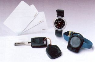
1.2.3 Erhältliche Transponder .................................................................................................................... 6
2. Technische Daten des Lesers..................................................................................................................... 7
2.1 Technische Daten der externen Antenne (optional)................................................................................. 7
3. Montage ........................................................................................................................................................ 8
3.1 Montage auf Unterputzdose..................................................................................................................... 9
3.2 Montage mit Aufputzrahmen ID APR-A ................................................................................................. 10
3.3 Leseranschluß........................................................................................................................................ 11
3.4 Anschluß der externen Antenne ID ZK.ANT-A an die ID ZK.AB-A ........................................................ 12
3.5 Anschlußschema der ID ZK.AB-A mit externer Antenne ID ZK.ANT-A ................................................. 13
3.6 Konfiguration der ID ZK.AB-A bei Verwendung der externen Antenne ID ZK.ANT-A ............................... 14
3.7 Programmierung der ID ZK.AB-A bei Verwendung der externen Antenne ID ZK.ANT-A ................................ 15
3.8 Funktionstest.......................................................................................................................................... 16
4. Programmierung ........................................................................................................................................ 17
4.1 Display Übersicht ................................................................................................................................... 17
4.2 Wie kann ich einen Speicherplatz zum programmieren auswählen ? ................................................... 18
4.3 Transponder in die ID ZK.AB-A programmieren: ................................................................................... 19
4.4 Transponder aus der ID ZK.AB-A löschen............................................................................................. 20
4.5 Relaishaltezeit konfigurieren .................................................................................................................. 21
4.6 Eine 2.Masterkarte programmieren ....................................................................................................... 22
4.7 Die 2.Masterkarte löschen: .................................................................................................................... 23
Anhang A: Reichweiten von Transponder-Typen....................................................................................... 44
Anhang B1: Abmessungen Unterputzmontage .......................................................................................... 45
Anhang B2: Abmessungen mit ID APR-A bei Aufputzmontage ................................................................ 46
Anhang C: Zuordnungsliste.......................................................................................................................... 47
Anhang D: Sicherheits- und Warnhinweise - vor Inbetriebnahme unbedingt lesen ............................... 51
Anhang E: Zulassung .................................................................................................................................... 51
FEIG ELECTRONIC GmbH M00500.0de-ID-B.DOC Seite 2 von 52®
Identifikationssystem OBID Montageanleitung ID ZK.AB-A
Contents
Contents............................................................................................................................................................ 3
General............................................................................................................................................................ 24
1. Components ............................................................................................................................................... 25
1.1 Delivery volume of the ID ZK.AB-A (compact access control) ................................................................... 25
1.2 Optional accessories.............................................................................................................................. 25
1.2.1 ID ZK.ANT-A (external antenna) ..................................................................................................... 25
1.2.2 Surface frame ID APR-A ................................................................................................................. 25
1.2.3 Available transponder types............................................................................................................ 26
2. Technical reader data ................................................................................................................................ 27
2.1 Technical data of external antenna (optional) ........................................................................................ 27
3. Installation .................................................................................................................................................. 28
3.1 Installation upon flush socket ................................................................................................................. 29
3.2 Installation with surface frame ID APR-A ............................................................................................... 30
3.3 Reader connection ................................................................................................................................. 31
3.4 Connection of external antenna ID ZK.ANT-A and ID ZK.AB-A............................................................ 32
3.5 Connection schme of ID ZK.AB-A with external antenna ID ZK.ANT-A ................................................ 33
3.6 Configuration of ID ZK.AB-A with external antenna ID ZK.ANT-A............................................................ 34
3.7 Programming of D ZK.AB-A with external antenna ID ZK.ANT-A.................................................................. 35
3.8 Performance check ................................................................................................................................ 36
4. Programming.............................................................................................................................................. 37
4.1 Display outline ........................................................................................................................................ 37
4.2 How to select a storage location for programming................................................................................. 38
4.3 How to program the transponder in the ID ZK.AB-A ............................................................................. 39
4.4 How to delete the transponder from the ID ZK.AB-A ............................................................................ 40
4.5 How to configurate the relay holding time .............................................................................................. 41
4.6 How to program a second “Masterkarte“ ............................................................................................... 42
4.7 How to delete the second “Masterkarte“ ................................................................................................ 43
Appendix A: ranges of various transponder types.................................................................................... 44
Anhang B1: dimensions for concealed mounting ...................................................................................... 45
Anhang B2: dimensions with ID APR-A for surface mounting.................................................................. 46
Anhang C: reference list................................................................................................................................ 47
Anhang D: safety instructions - please read carefully prior to initiation ................................................. 50
Anhang E: certification.................................................................................................................................. 50
FEIG ELECTRONIC GmbH M00500.0de-ID-B.DOC Seite 3 von 52®
Identifikationssystem OBID Montageanleitung ID ZK.AB-A
Allgemeines
Die Kompakt-Zutrittskontrollanlage ID ZK.AB-A ist ein ReadOnly (RO)-Terminal, welches
als „Stand alone“-Gerät keine Anbindung an einen PC oder eine Steuereinheit benötigt.
Neben RO-Transpondern kann die ID ZK.AB-A auch Read/Write (RW)-Transponder
verarbeiten, die z.B. innerhalb von Abrechnungs-, Schließ- oder anderen
Zutrittskontrollsystemen verwendet werden. Insgesamt kann die ID ZK.AB-A 200
Benutzertransponder im Rahmen ihres Einsatzgebietes zur Überwachung einer Tür, eines
Drehkreuzes oder einer Schranke verwalten. Die Transponder werden einzeln, mit Hilfe
einer jedem Gerät beiliegenden Masterkarte programmiert und bei Bedarf auch wieder
aus dem System gelöscht. Mit dieser Masterkarte (im folgenden „Werksmasterkarte“
genannt) kann auch eine zweite Masterkarte programmiert und wieder gelöscht werden.
Die ID ZK.AB-A verfügt über ein integriertes Relais, mit dem z.B. ein handelsüblicher
Türöffner angesteuert werden kann. Die Relaishaltezeit wird mit Hilfe der Masterkarte
eingestellt und kann zwischen 0,5 und 9 Sekunden betragen.
Obwohl die ID ZK.AB-A über eine integrierte Antenne verfügt, ist optional eine externe
Antenne (ID ZK.ANT-A) erhältlich. Eine solche externe Antenne kann z.B. von außen an
einem Objekt angebracht und mit der innen installierten ID ZK.AB-A verbunden werden.
Somit befindet sich die Relaissteuerung z.B. einer Tür geschützt im Innenbereich und ist
vor Sabotage geschützt.
Die Spannungsversorgung erfolgt wahlweise über ein 12-24 V Gleichspannungs- oder
über ein 12-15 V Wechselspannung.
ID ZK.AB-A und ID ZK.ANT-A werden standardmäßig in einem Unterputzgehäuse
geliefert; optional kann jedoch für beide Geräte ein Aufputzgehäuse bestellt werden.
UWH
WH
WH V
U
DV
DV HUN
UND
UND
:
WH
0
0
'LH:HUNVPDVWHUNDUWH 'LH0DVWHUNDUWH
LVW%HVWDQGWHLO NDQQPLW+LOIHGHU
GHU/LHIHUXQJ :HUNVPDVWHUNDUWHVHOEVW
HUVWHOOWZHUGHQ
FEIG ELECTRONIC GmbH M00500.0de-ID-B.DOC Seite 4 von 52® Identifikationssystem OBID Montageanleitung ID ZK.AB-A 1. Komponenten 1.1 Lieferumfang der ID ZK.AB-A (Kompakt Zutrittskontrolle) Bestellnr.: 1506.000.00 1 x Gehäuse-Unterteil (Unterputzgehäuse) 1 x Gehäuse-Oberteil mit Leserelektronik 1 x Anschlußplatine 1 x Klarsichtdeckel 1 x Frontaufkleber 1 x Schneidschraube 3,2 x 25 mm (zur Verbindung der Gehäuseteile) 2 x Schneidschrauben 3,2 x 15 mm (zur Wandmontage) 1 x Werksmasterkarte 1 x Montageanleitung 1.2 Optionales Zubehör 1.2.1 ID ZK.ANT-A (externe Antenne) Bestellnr.:1508.000.00 1 x Gehäuse-Unterteil (Unterputzgehäuse) 1 x Gehäuse-Oberteil mit Antenne 1 x Anschlußplatine 1 x 1m Anschlußkabel 1 x Klarsichtdeckel 1 x Frontaufkleber 1 x Schneidschraube 3,2 x 25 mm (zur Verbindung der Gehäuseteile) 2 x Schneidschrauben 3,2 x 15 mm (zur Wandmontage) 1 x Montageanleitung 1.2.2 Aufputzrahmen ID APR-A Bestellnr.: 1144.001.00 Für die Aufputzmontage ist ein entsprechender Aufputzrahmen ID APR-A erhältlich (siehe Kapitel 3.2). FEIG ELECTRONIC GmbH M00500.0de-ID-B.DOC Seite 5 von 52
®
Identifikationssystem OBID                                   Montageanleitung ID ZK.AB-A

1.2.3 Erhältliche Transponder

ReadOnly Transponder                                                      Bestellnummer:

ID CTK.A-P Karte blanko weiß mit aufgedruckter Seriennummer (VE=1Stück)    0915.004.00
ID CTA.A-A Schlüsselanhänger (VE=1Stück)                                   0277.001.00
ID CTW.A-A Uhr mit eingebautem Transponder (VE=1Stück)                     0315.001.00

Read/write Transponder                                                    Bestellnummer:

ID DTK.B-A read/write Karte, blanko weiß, (VE=20Stück)                     0070.001.00
ID DTK.B-A read/write Karte, blanko weiß, (VE=100 Stück)                   0070.001.01
ID DTA.B-A read/write Schlüsselanhänger (VE=1Stück)                        0095.001.00

FEIG ELECTRONIC GmbH               M00500.0de-ID-B.DOC                     Seite 6 von 52
®
Identifikationssystem OBID                                    Montageanleitung ID ZK.AB-A

2. Technische Daten des Lesers

 • Gehäuse                                Kunststoff ASA
 • Abmessung                              113 x 83 x 24,5 mm (L x B x H)
 • Farbe
   - Gehäuse-Oberteil:                    ähnlich RAL 9002 (grauweiß)
   - Gehäuse-Unterteil:                   ähnlich RAL 7043 (verkehrgrau)
 • Gewicht                                ca. 120 g
 • Schutzart                              IP 54
 • Spannungsversorgung                    12 – 24V DC / 12 - 15 V AC; 50-60 Hz
 • Stromaufnahme                          max. 0,2 A
 • Leistungsaufnahme                      max. 3,5 W
 • Temperaturbereich                      -25°C bis 70°C
 • relative Luftfeuchte                   95 % (nicht betauend)
 • Antenne                                integriert
 • externe Antenne (optional)             ID ZK.ANT-A
 • Datenübertragung mit Transponder       125 kHz / AM / halbduplex
 • Anzahl der zulässigen Transponder       max. 200 (0 bis 199)
 • unterstützte Transponder-Typen         l ID CTx.A
                                          l ID DTx.B
 • Anzeige                                l 2-stellige Sieben-Segmentanzeige
 • Relais                                 1 x Wechsler
                                              Kontaktbelastbarkeit: 1,5A / 24V AC/DC
 • EEPROM                                 1.000.000 Schreibzyklen

2.1 Technische Daten der externen Antenne (optional)

 • Gehäuse                                Kunststoff ASA
 • Abmessung                              113 x 83 x 24,5 mm (L x B x H)
 • Farbe
   - Gehäuse-Oberteil:                    ähnlich RAL 9002 (grauweiß)
   - Gehäuse-Unterteil:                   ähnlich RAL 7043 (verkehrgrau)
 • Gewicht                                ca. 120 g
 • Schutzart                              IP 54
 • Spannungsversorgung                    über ID ZK.AB-A
 • Anschlußleitung                        max 1,25m, 2x3x0,25qmm (liegt bei)
 • Temperaturbereich                      -25°C bis 70°C
 • relative Luftfeuchte                   95 % (nicht betauend)
 • Anzeige                                • LED zweifarbig (rot, grün)

FEIG ELECTRONIC GmbH                   M00500.0de-ID-B.DOC                     Seite 7 von 52
®
Identifikationssystem OBID Montageanleitung ID ZK.AB-A
3. Montage
Der Leser ist für die Wandmontage auf eine 60 mm Unterputzdose vorgesehen. Für die
Aufputzmontage kann das Gehäuseunterteil durch den Aufputzrahmen ID APR-A, der als Zubehör
lieferbar ist, ersetzt werden.
HINWEISE:
l Der Leser sollte nicht direkt auf leitende Materialien wie Metallflächen, Metallgitter
(Armieren) oder metallisierte Oberflächen montiert werden, da diese Flächen eine
Reduzierung der Lesereichweite bewirken. Der Abstand zu derartigen Flächen sollte
mindestens 3 cm betragen.
l Ist eine Montage auf einer Metalloberfläche notwendig, kann zur Einhaltung des
Mindestabstandes der Aufputzrahmen ID APR-A eingesetzt werden.
l Der räumliche Abstand zu benachbarten Lesern gleicher Bauart sollte mindestens
30 cm betragen.
l Vor der endgültigen Installation sollte der geplante Installationsort auf seine
Tauglichkeit geprüft werden.
l Die Gehäuseöffnung (A), (siehe Abbildung 1: Montageausrichtung) muß nach unten
montiert werden!
Abbildung 1: Montageausrichtung (A) nach unten
FEIG ELECTRONIC GmbH M00500.0de-ID-B.DOC Seite 8 von 52®
Identifikationssystem OBID Montageanleitung ID ZK.AB-A
3.1 Montage auf Unterputzdose
1. Montageort auswählen:
Die Montage sollte auf einem ebenen Untergrund erfolgen.
2. Anschluß:
siehe Kapitel 3.3 –3.5
3. Inbetriebnahme:
l Anschlußplatine in das Gehäuse-Unterteil einrasten (siehe: Abbildung 2: Rückansicht mit
eingerasteter Anschlußplatine (1)).
l Gehäuse-Oberteil auf Gehäuse-Unterteil stecken. Dabei die Stiftleiste der Leserelektronik
sauber in Buchsenleiste X3 einführen!
l siehe Kapitel 3.8 Funktionstest
4. Wandmontage:
Die Wandmontage sollte erst nach Kontrolle der Inbetriebnahmearbeiten erfolgen.
l Gehäuseoberteil vom Gehäuseunterteil abziehen.
l Gehäuseunterteil mit eingerasteter Anschlußplatine auf Untergrund verschrauben.
l Gehäuseoberteil auf Gehäuseunterteil stecken. Dabei die Stiftleiste der Leserelektronik
sauber in Buchsenleiste X3 einführen!
l Gehäuseoberteil mit Schneidschraube 3,2 x 25 mm auf Gehäuseunterteil verschrauben.
l Klarsichtscheibe einsetzen und Frontaufkleber auf das saubere und fettfreie Gehäuse
aufkleben.
EA2 EA1 ASW NO COM NC -/~ +/~
IN1 GND GN RO
X3
(1)
Abbildung 2: Rückansicht mit eingerasteter Anschlußplatine (1)
FEIG ELECTRONIC GmbH M00500.0de-ID-B.DOC Seite 9 von 52®
Identifikationssystem OBID Montageanleitung ID ZK.AB-A
3.2 Montage mit Aufputzrahmen ID APR-A
1. Wandmontage:
l Die Montage sollte auf einem möglichst ebenen Untergrund erfolgen.
l Durchbrüche für Zuleitung im Gehäuse-Unterteil herstellen, Würgenippel einsetzen und
Zuleitung einziehen.
l Gehäuse-Unterteil mit Untergrund verschrauben.
2. Anschluß:
siehe Kapitel 3.3 – 3.5
3. Gehäuse schließen:
l Anschlußplatine (1) gem. Abbildung 3 mit den Anschlußklemmen nach unten in das
Gehäuseunterteil einrasten. Dazu die Rasthaken mit den Fingern leicht auseinanderdrücken.
l Gehäuseoberteil auf Gehäuseunterteil stecken. Dabei die Stiftleiste der Leserelektronik
sorgfältig in Buchsenleiste X3 einführen!
l Gehäuseoberteil und Gehäuseunterteil mit Schneidschraube 3,2 x 25 mm verschrauben.
4. Inbetriebnahme:
siehe Kapitel 3.8 Funktionstest
5. Klarsichtscheibe und Frontaufkleber anbringen:
Klarsichtscheibe einsetzen und Frontaufkleber auf das saubere und fettfreie Gehäuse
aufkleben
X3
Abbildung 3: Aufputzmontage
Offener Aufputzrahmen mit eingesetzter Anschlußplatine (1)
FEIG ELECTRONIC GmbH M00500.0de-ID-B.DOC Seite 10 von 52®
Identifikationssystem OBID Montageanleitung ID ZK.AB-A
3.3 Leseranschluß
Hinweis:
An die ID ZK.AB-A kann optional eine externe Antenne (ID ZK.ANT-A) angeschlossen
werden. Anweisungen zur Installation entnehmen Sie bitte dem Kapitel 3.4 Anschluß der
externen Antenne.
Der Anschluß des Lesers erfolgt über die Anschlußplatine (siehe: Abbildung 4: Anschlußplatine),
die im Gehäuseunterteil eingerastet wird.
RO GN GND IN1
X3 X1
X2
+/≈ -/≈ NC COM NO ASW EA1 EA2
Abbildung 4: Anschlußplatine der ID ZK.AB-A
Klemme Funktion
Leiste Bezeichnung ID ZK.AB-A
X2 +/≈ Spannungsversorgung (DC+,DC-,AC≈)
-/≈ Spannungsversorgung(DC+,DC-,AC≈)
NC Relais – NC
COM Relais – COM
NO Relais – NO
ASW -
EA1 Anschluß externe Antenne (ID ZK.ANT-A)
EA2 Anschluß externe Antenne (ID ZK.ANT-A)
X1 RO LED rot (ID ZK.ANT-A)
GN LED grün (ID ZK.ANT-A)
GND Interner GND (ID ZK.ANT-A)
IN1 -
Tabelle 1: Klemmenbelegung der Anschlußplatine (ID ZK.AB-A)
FEIG ELECTRONIC GmbH M00500.0de-ID-B.DOC Seite 11 von 52®
Identifikationssystem OBID Montageanleitung ID ZK.AB-A
3.4 Anschluß der externen Antenne ID ZK.ANT-A an die ID ZK.AB-A
Der Anschluß der externen Antenne erfolgt über die Anschlußplatine (siehe: Abbildung 4:
Anschlußplatine), die im Gehäuseunterteil eingerastet wird.
RO GN GND IN1
X3 X1
X2
+/≈ -/≈ NC COM NO ASW EA1 EA2
Abbildung 5: Anschlußplatine ID ZK.ANT-A
Klemme Funktion
Leiste Bezeichnung ID ZK.ANT-A
X2 +/≈ -
-/≈ -
NC -
COM -
NO -
ASW -
EA1 Anschluß externe Antenne (ID ZK.ANT-A)
EA2 Anschluß externe Antenne (ID ZK.ANT-A)
X1 RO LED rot (ID ZK.ANT-A)
GN LED grün (ID ZK.ANT-A)
GND Interner GND (ID ZK.ANT-A)
-
Tabelle 2: Klemmenbelegung der Anschlußplatine (ID ZK.ANT-A)
FEIG ELECTRONIC GmbH M00500.0de-ID-B.DOC Seite 12 von 52®
Identifikationssystem OBID Montageanleitung ID ZK.AB-A
3.5 Anschlußschema der ID ZK.AB-A mit externer Antenne ID ZK.ANT-A
Aus Sicherheitsgründen kann es gewünscht sein eine externe Antenne zu verwenden, um die
Elektronik vor Sabotage zu schützen.
Dem externen Antennenmodul ID ZK.ANT-A wird ein 1,25m langes Kabel beigelegt, welches an
die Anschlußplatine der ID ZK.AB-A angeschlossen wird (siehe Kapitel 3.3 u. 3.4, Tabelle1-2, und
Abbildung 6).
7U|IIQHU
3RZHUVXSSO\
9'&
9$&
, ' = . $ 1 7$ ,'=.$%$
URVD URVD
JUQ JUQ
JUDX JUDX
ZHLVV ZHLVV
EUDXQ EUDXQ
$QVFKOXNDEHOIUH[WHUQH$QWHQQH
PD[P
/L®
Identifikationssystem OBID Montageanleitung ID ZK.AB-A
3.6 Konfiguration der ID ZK.AB-A bei Verwendung der externen Antenne ID ZK.ANT-A
Nachdem die externe Antenne ID ZK.ANT-A an die ID ZK.AB-A angeschlossen wurde, muß der
Jumper X3 auf die Position „2-3“ gesteckt werden.
Dadurch wird:
1. die externe Antenne aktiviert und
2. eine kleine Hilfsantenne in der ID ZK.AB-A zur Verfügung gestellt, um die Programmierung
der Ausweise zu erleichtern (siehe Kapitel 3.7)
Jumper X3 Konfiguration: 321
interne Antenne X3 => 1-2 X3
EXT INT
externe Antenne X3 => 2-3
Abbildung 7: Rückansicht des Gehäusedeckels mit eingesetzter Leserelektronik
FEIG ELECTRONIC GmbH M00500.0de-ID-B.DOC Seite 14 von 52®
Identifikationssystem OBID Montageanleitung ID ZK.AB-A
3.7 Programmierung der ID ZK.AB-A bei Verwendung der externen Antenne ID ZK.ANT-A
Die Programmierung der ID ZK.AB-A sollte bei Verwendung der externen Antenne grundsätzlich
auch über diese erfolgen. Sollte das aufgrund der örtlichen Gegebenheiten nicht möglich sein, so
kann die Programmierung auch über die Hilfsantenne, welche in dem Gehäuse der ID ZK.AB-A
integriert ist, durchgeführt werden. Es ist jedoch zu berücksichtigen, daß die Reichweite dieser
Hilfsantenne stark eingeschränkt ist. Aus diesem Grund sollte man erst die beste
Empfangsposition der Masterkarte ermitteln, um die anschließende Programmierung zu
erleichtern.
Legen Sie dazu den Transponder in die, in der Abbildung 8 angegebene Position. Der
Transponder sollte sich dabei direkt auf der Gehäuseoberfläche der ID ZK.AB-A befinden.
Die Lage der Hilfsantenne ist in der Abbildung 8 ersichtlich. Andere Transponder Bauformen sind
entspreched auszurichten.
Position der
internen
Hilfsantenne
Transponder Karte
Abbildung 8: Frontansicht des Gehäusedeckels der ID ZK.AB-A
FEIG ELECTRONIC GmbH M00500.0de-ID-B.DOC Seite 15 von 52®
Identifikationssystem OBID Montageanleitung ID ZK.AB-A
3.8 Funktionstest
l Spannungsversorgung für die ID ZK.AB-A einschalten
l Mittels Masterkarte einen Transponder zulassen
(siehe Kapitel 4.Programmierung)
l einen Transponder vor den Leser halten.
oder
l einen Transponder vor die externe Antenne halten (falls vorhanden).
Das Gerät arbeitet richtig wenn:
bei einem bereits programmierten l der Speicherplatz des
Transponder Transponders in der
LED-Anzeige der ID ZK.AB-A
angezeigt wird
l die LED in der externen Antenne ID ZK.ANT-A
grün leuchtet
l das Relais der ID ZK.AB-A schaltet
bei einem noch nicht l in der LED-Anzeige zwei Striche
programmierten Transponder (--) zu sehen sind
l die LED in der externen Antenne ID ZK.ANT-A
rot leuchtet
l das Relais der Zutrittskontrolle nicht schaltet
FEIG ELECTRONIC GmbH M00500.0de-ID-B.DOC Seite 16 von 52®
Identifikationssystem OBID Montageanleitung ID ZK.AB-A
4. Programmierung
4.1 Display Übersicht
Speicherplatz Speicherplatz
10er-Stelle 1er-Stelle
Wenn die Anzeige blinkt
können Änderungen
vorgenommen werden
Speicherplatz: Speicherplatz:
100er-Stelle belegt
1 Hier werden die 10er-Stellen des aktuellen Speicherplatzes angezeigt.
(10 ; 20 ; 30 ; ........90 ; 1.0 ; 2.0 ; 3.0 ; ........9.0 ;)
2 Hier werden die 1er-Stellen des aktuellen Speicherplatzes angezeigt.
(Von 0 bis 9)
3 Der linke Dezimalpunkt symbolisiert die 100er-Stelle.
(Ab dem Speicherplatz 100 leuchtet der linke Dezimalpunkt (z.B.für 153)
Bei den Speicherplätzen von 0 bis 99 leuchtet der Dezimalpunkt nicht) (z.B.für 53)
4 Der rechte Dezimalpunkt zeigt an, daß der aktuelle Speicherplatz belegt ist.
(Die Anzeige besagt: der Speicherplatz 138 ist durch einen Transponder belegt)
Weitere Betriebsanzeigen:
Der im Erfassungsbereich befindliche Transponder
wurde noch nicht programmiert
Fehlfunktion!
Das Gerät arbeitet nicht einwandfrei, es liegt ein
interner Fehler vor.
Bitte schicken Sie das Gerät zur Reparatur
FEIG ELECTRONIC GmbH M00500.0de-ID-B.DOC Seite 17 von 52®
Identifikationssystem OBID Montageanleitung ID ZK.AB-A
4.2 Wie kann ich einen Speicherplatz zum programmieren auswählen ?
Die Masterkarte in l Die Anzeige schaltet
das Antennenfeld sich ein
halten
UWH
UND
WH
DV
0
l Die Speicherplätze
werden von 0 bis 10
in 1er Schritten
angezeigt
00...01...02...03...
l Ab dem 10.
Speicherplatz wird
in 10er Schritten
(Schnellmodus)
weiter gezählt
10...20...30...40...
Durch Entfernen der l Die Anzeige bleibt
Masterkarte kann stehen
UWH
0DVWHUND
der Zähler
angehalten werden.
Durch erneutes
Einführen der l Die nächsten 10
Masterkarte in das Anzeigen werden in
Antennenfeld, wird 1er Schritten weiter
in 1er Schritten gezählt.
weiter gezählt. VWH
UND
UWH
l Anschließend wird 31...32...33...34...
D
0 wieder in den
Schnellmodus
geschaltet
Bei dem l Der Speicherplatz
gewünschten leuchtet für ca. 3 s
UWH
0DVWHUND
Speicherplatz ist die dauerhaft auf
Masterkarte aus
dem Antennenfeld
zu entfernen.
(im Beispiel 35)
l Danach beginnt die
Anzeige für ca. 6s
zu blinken und der
Speicherplatz kann
programmiert oder
gelöscht werden
FEIG ELECTRONIC GmbH M00500.0de-ID-B.DOC Seite 18 von 52®
Identifikationssystem OBID Montageanleitung ID ZK.AB-A
4.3 Transponder in die ID ZK.AB-A programmieren:
ACHTUNG: Bei der Programmierung ist darauf zu achten, daß kein bereits belegter
Speicherplatz mit einer neuen Nummer überschrieben wird, da der Transponder, dessen
Nummer überschrieben wird, hierdurch seine Zutrittsberechtigung verliert.
Die Masterkarte in l im Beispiel 35
das Antennenfeld
bringen und den
gewünschten
UWH
Speicherplatz WH
UND
DV
auswählen 0
(siehe Kapitel 4.2)
Bei dem gewünschten l Der Speicherplatz
Speicherplatz ist die 35 leuchtet für
UWH
0DVWHUND
Masterkarte aus dem ca. 3 s
Antennenfeld zu
entfernen.
(im Beispiel 35)
l Danach beginnt die
Anzeige für ca. 6s
zu blinken
Während die Anzeige l Der Transponder wird
blinkt, den neuen in dem gewählten
Transponder in den Speicherplatz
HU
Erfassungsbereich 1
HX
GH
U programmiert und der
RQ
der ID ZK.AB-A QVS LV rechte Dezimalpunkt
7UD ZH
XV
bringen $
leuchtet
l Hinweis:
Den Transponder Wurde ein bereits
U gespeicherter Transponder
wieder aus dem U H
eingeführt, so springt die
H G
Erfassungsbereich H
X Q LV
R H
Anzeige zu dessen
Z
entfernen 1
S V
V X Speicherplatz
Q $
UD
7
l Die Anzeige springt
zum nächsten
Speicherplatz
Während die Anzeige l Der Transponder
blinkt, kann der wird in den gewählten
nächste Transponder Speicherplatz
HU
in den 1
HX U programmiert und
GH
RQ
Erfassungsbereich QVS LV
der rechte
7UD ZH
XV
gebracht werden $
Dezimalpunkt
oder leuchtet
so lange gewarten l Die Anzeige erlischt
werden bis die
Anzeige erlischt und
damit die ID ZK.AB-A
in den Betriebsmodus
übergeht
FEIG ELECTRONIC GmbH M00500.0de-ID-B.DOC Seite 19 von 52®
Identifikationssystem OBID Montageanleitung ID ZK.AB-A
4.4 Transponder aus der ID ZK.AB-A löschen
Die Masterkarte in l der rechte
das Antennenfeld Dezimalpunkt
bringen und den leuchtet: der
belegten UWH
Speicherplatz ist
UND
Speicherplatz DV
WH belegt
0
auswählen (im Beispiel 35)
(siehe Kapitel 4.2)
Die Masterkarte aus l Der Speicherplatz
dem Antennenfeld leuchtet für ca. 3 s
UWH
0DVWHUND
entfernen dauerhaft
l Danach beginnt die
Anzeige für ca. 6s
zu blinken
Während die Anzeige l Der Speicherplatz
blinkt, Masterkarte wird gelöscht und
erneut in den der rechte
Erfassungsbereich UWH
Dezimalpunkt geht
UND
der ID ZK.AB-A 0
DV
WH aus
bringen
FEIG ELECTRONIC GmbH M00500.0de-ID-B.DOC Seite 20 von 52®
Identifikationssystem OBID Montageanleitung ID ZK.AB-A
4.5 Relaishaltezeit konfigurieren
Die Haltezeit des eingebauten Relais kann vom Benutzer von 0,5s bis 9s eingestellt werden.
Werksseitig ist eine Haltezeit von 4 Sekunden eingestellt.
Die Masterkarte in l nach der
das Antennenfeld Speicheradresse
bringen und solange 190 (9.0)
im Antennenfeld UND
UWH
VWH
belassen bis die 0
D
gewünschte l erscheint die
Relaishaltezeit Anzeige „M“
1
erscheint
H0 = 0,5 Sekunden l anschließend
H1 = 1 Sekunde werden die
H2 = 2 Sekunden Relaishaltezeiten
... von „H0“ bis „H9“
2
H9 = 9 Sekunden hoch gezählt
Bei der gewünschten l die Anzeige leuchtet
Relaishaltezeit die für ca. 3 s dauerhaft
UWH
0DVWHUND
Masterkarte aus dem
Antennenfeld
entfernen
(im Beispiel H5)
l Danach beginnt die
Anzeige für ca. 6s
zu blinken
Während die Anzeige l Die Relaishaltezeit H5
blinkt, die Masterkarte = 5 Sekunden wird
erneut in den programmiert, der
UWH
UND rechte Dezimalpunkt
Erfassungsbereich der DVWH
0
ID ZK.AB-A bringen leuchtet
Die Masterkarte kann l Die Anzeige erlischt
UWH
entfernt werden.
0DVWHUND
Die Programmierung
der Relaishaltezeit ist
abgeschlossen
1
nur bei Verwendung der Werksmasterkarte
2
die aktuelle Relaishaltezeit wird durch den rechten Dezimalpunkt gekennzeichnet
FEIG ELECTRONIC GmbH M00500.0de-ID-B.DOC Seite 21 von 52®
Identifikationssystem OBID Montageanleitung ID ZK.AB-A
4.6 Eine 2.Masterkarte programmieren
Um ein Höchstmaß an Sicherheit zu gewährleisten, kann die Werksmasterkarte nur von der
Firma FEIG ELECTRONIC GmbH programmiert werden. Deshalb sollte diese unbedingt an
einem sicheren Ort aufbewahrt werden.
Es besteht die Möglichkeit, neben der Werksmasterkarte einen weiteren Transponder als
2.Masterkarte zuzulassen. Hierzu wird die mitgelieferte Werksmasterkarte benötigt.
Die l nach der
Werksmasterkarte in Speicheradresse
das Antennenfeld 190 (9.0)
bringen und solange NV
UWH
HU
: UND
im Antennenfeld 0
DV
WH
belassen bis ein „M“ l erscheint in der
1
in der Anzeige Anzeige ein „M“
erscheint
Die l die Anzeige leuchtet
Werksmasterkarte H
UW
für ca. 3 s dauerhaft
D
aus dem
V
UN
UN WH
Antennenfeld H
V
D
: 0
entfernen
l Danach beginnt die
Anzeige für ca. 6s
zu blinken
Während die Anzeige l Der neue
blinkt, ist der Transponder ist nun
Transponder welcher als 2.Masterkarte
als 2.Masterkarte HU programmiert, der
1HXRQGHU
dienen soll in den VS rechte Dezimalpunkt
Erfassungsbereich zu 7UDQ leuchtet
bringen.
Die 2.Masterkarte H
l Die Anzeige erlischt
UW
kann entfernt werden. D
UN
Die Programmierung WH
V
ist abgeschlossen D
0
Hinweis:
Ein bereits als Ausweis gespeicherter Transponder kann nicht als 2.Masterkarte verwendet
werden. In diesem Fall springt die Anzeige zu dem entsprechenden Speicherplatz.
1
nur bei Verwendung der Werksmasterkarte
FEIG ELECTRONIC GmbH M00500.0de-ID-B.DOC Seite 22 von 52®
Identifikationssystem OBID Montageanleitung ID ZK.AB-A
4.7 Die 2.Masterkarte löschen:
Das Löschen der Werksmasterkarte ist nicht möglich.
Für das Löschen der 2.Masterkarte wird die "Werksmasterkarte" benötigt.
Die l nach der
Werksmasterkarte in Speicheradresse
das Antennenfeld 190 (9.0)
bringen und den NV
UWH
HU
: UND
gewünschten 0
D VWH
Speicherplatz l erscheint die
auswählen Anzeige „M.“ mit
(siehe Kapitel 4.3) einem rechten
1
Dezimalpunkt
Die l die Anzeige leuchtet
Werksmasterkarte H
UW
für ca. 3 s dauerhaft
D
aus dem UN
V
UN WH
Antennenfeld H
V
D
entfernen : 0
l Danach beginnt die
Anzeige für ca. 6s
zu blinken
Während die Anzeige l Die 2.Masterkarte
blinkt, die wird gelöscht und
Werksmasterkarte der rechte
erneut in den
Dezimalpunkt geht
NV UWH
HU
Erfassungsbereich :
VWH
UND aus
D
0
der ID ZK.AB-A
bringen
Die l Die Anzeige erlischt
Werksmasterkarte H
UW
D
kann entfernt werden.
N
U
V
UN WH
Die Programmierung H
V
D
ist abgeschlossen : 0
1
Nur wenn vorher bereits eine 2.Masterkarte programmiert wurde
FEIG ELECTRONIC GmbH M00500.0de-ID-B.DOC Seite 23 von 52®
Identifikationssystem OBID Montageanleitung ID ZK.AB-A
General
The compact access control system ID ZK.AB-A is a ReadOnly (RO)-terminal. Being a so-
called „stand alone“-device, it does not need to be connected to a PC or control unit. Apart
from RO-transponders, ID ZK.AB-A is also able to handle Read/Write (RW)-
transponders which are used in accounting-, locking- or other access control systems.
ID ZK.AB-A is able to manage up to 200 user transponders within their field of application
for the control of doors, turnstiles or gates. The transponders are programmed resp.
deleted individually with the help of the enclosed “Masterkarte“. With the help of this
“Masterkarte“ (also called factory “Masterkarte“ in the following) you may even program or
delete a second “Masterkarte“.
ID ZK.AB-A has an integrated relay, which may for instance trigger a usual commercial
door opener. The relay holding time is adjusted with the help of a “Masterkarte“ and
ranges from 0,5 to 9 seconds.
Although ID ZK.AB-A disposes of an integrated antenna, an external antenna is also
available (ID ZK.ANT-A). Such an external antenna can be mounted at the outside of an
object and connected with the ID ZK.AB-A, which is located inside. Thus, the relay control
of a door, for instance, is located safely inside and protected against acts of sabotage.
Power supply may either be 12-24 V DC or 12-15 V AC.
ID ZK.AB-A and ID ZK.ANT-A generally come in a concealed housing. However, a
surface housing is available for both devices upon request.
WH U \
UWH
UWH
DV WR
WH
UND
UND
D V
0 )DF
0
7KH 7KHVHFRQG´0DVWHUNDUWHµ
IDFWRU\´0DVWHUNDUWHµ PD\EHSURJUDPPHGE\
LVDSDUWRIWKHGHOLYHU\ WKHIDFWRU\´0DVWHUNDUWHµ
FEIG ELECTRONIC GmbH M00500.0de-ID-B.DOC Seite 24 von 52® Identifikationssystem OBID Montageanleitung ID ZK.AB-A 1. Components 1.1 Delivery volume of ID ZK.AB-A (compact access control) Part No.: 1506.000.00 1 x housing; lower part (concealed housing) 1 x housing; upper part with reader electronics 1 x connecting board 1 x transparent cover 1 x front sticker 1 x tap screw 3,2 x 25 mm (used for connection of housing parts) 2 x tap screws 3,2 x 15 mm (used for wall fastening) 1 x factory “Masterkarte“ 1 x mounting instructions 1.2 Optional accessories 1.2.1 ID ZK.ANT-A (external antenna) Part No.:1508.000.00 1 x housing; lower part (concealed housing) 1 x housing; upper part with antenna 1 x connecting board 1 x 1m connection cable 1 x transparent cover 1 x front sticker 1 x tap screw 3,2 x 25 mm (used for connection of housing parts) 2 x tap screws 3,2 x 15 mm (for wall fastening) 1 x mounting instructions 1.2.2 Surface frame ID APR-A Part No.: 1144.001.00 The appropriate surface frame ID APR-A is available for surface mounting. (please refer to chapter 3.2). FEIG ELECTRONIC GmbH M00500.0de-ID-B.DOC Seite 25 von 52
®
Identifikationssystem OBID                                       Montageanleitung ID ZK.AB-A

1.2.3 Available transponder types

ReadOnly transponders                                                        Part No:

ID CTK.A-P card, blank white with imprinted serial No. (VE=1piece)             0915.004.00
ID CTA.A-A key ring (VE=1piece)                                                0277.001.00
ID CTW.A-A wristwatch with integrated transponder (VE=1piece)                  0315.001.00

Read/write transponders                                                      Part No.:

ID DTK.B-A read/write card, blank white (VE=20 pcs.)                           0070.001.00
ID DTK.B-A read/write card, blank white (VE=100 pcs.)                          0070.001.01
ID DTA.B-A read/write key ring (VE=1 piece)                                    0095.001.00

FEIG ELECTRONIC GmbH                M00500.0de-ID-B.DOC                       Seite 26 von 52
®
Identifikationssystem OBID                                     Montageanleitung ID ZK.AB-A

2. Technical reader data

 • Housing                                Plastic ASA
 • Dimensions                             113 x 83 x 24,5 mm (L x W x H)
 • Colour
   - housing; upper part:                 similar to RAL 9002 (grey-white)
   - housing; lower part:                 similar to RAL 7043 (traffic grey)
 • Weight                                 Approx. 120 g
 • Protective system                      IP 54
 • Power supply                           12 – 24V DC / 12 - 15 V AC; 50-60 Hz
 • Current consumption                    max. 0,2 A
 • Power consumption                      max. 3,5 W
 • Temperature range                      -25°C to 70°C
 • relative air moisture                  95 % (non-thawing)
 • Antenna                                Integrated
 • External antenna (optional)            ID ZK.ANT-A
 • Data transmission via transponder      125 kHz / AM / semi-duplex
 • Number of admitted transponders         max. 200 (0 to 199)
 • Supported transponder types            l ID CTx.A
                                          l ID DTx.B
 • Display                                l Two-digit seven-segments display
 • Relay                                  1 x change-over contact
                                          Max. contact load: 1,5A / 24V AC/DC
 • EEPROM                                 1.000.000 writing cycles

2.1 Technical data of the external antenna (optional)

 • Housing                                Plastic ASA
 • Dimensions                             113 x 83 x 24,5 mm (L x W x H)
 • Colour
   - housing; upper part:                 similar to RAL 9002 (grey-white)
   - housing; lower part:                 similar to RAL 7043 (traffic grey)
 • Weight                                 Approx. 120 g
 • Protective system                      IP 54
 • Power supply                           Via ID ZK.AB-A
 • Connection cable                       Max 1,25m, 2x3x0,25qmm (enclosed)
 • Temperature range                      -25°C to 70°C
 • Relative air moisture                  95 % (non-thawing)
 • Display                                • Bicolor LED (red, green)

FEIG ELECTRONIC GmbH                   M00500.0de-ID-B.DOC                     Seite 27 von 52
®
Identifikationssystem OBID Montageanleitung ID ZK.AB-A
3. Installation
The reader is intended for wall fastening upon a 60 mm flush socket. In case of surface mounting,
the lower part of the housing can be replaced by surface frame ID APR-A, which is available as an
accessory part.
Important hints:
l The reader should not be installed directly on conducting materials, such as metallic
surfaces, metal grids (armouring) or metallized surfaces, since these surfaces lead to a
reduction in the reading range. Please keep a minimum distance of 3 cm.
l Should there be any necessity for installation on a metallic surface, the surface frame
ID APR-A may be used in order to keep the minimum distance.
l Der spatial distance between neighbouring readers of similar types should be at least
30 cm.
l Prior to the final installation, the intended place of installation should be checked with
regard to its capability.
l The housing opening (A), (see illustr. 1) has to be mounted pointing downwards!
Illustration 1: mounting direction (A) downwards
FEIG ELECTRONIC GmbH M00500.0de-ID-B.DOC Seite 28 von 52®
Identifikationssystem OBID Montageanleitung ID ZK.AB-A
3.1 Installation upon flush socket
1. Choose place of installation:
Installation should be carried out on an even surface.
2. Connection:
see chapter 3.3 –3.5
3. Initiation:
l Let the connecting board lock into the lower part of the housing (see: illustr. 2, rear view with
locked connecting board (1).
l Put the upper part of the housing on the lower part. Make sure that you insert the contact
terminal strip exactly into socket terminal strip X3 !
l See also: chapter 3.8: performance check
5. Wall fastening:
Please check initiation works prior to wall fastening.
l Remove the upper part of the housing from the lower part.
l Fasten the lower part of the housing to the wall with the connecting board being locked.
l Put the upper part of the housing on the lower part. Make sure that the contact terminal strip of
the reader electronics is inserted exactly into socket terminal strip X3!
l Fasten the upper part of the housing on the lower part with the help of the 3,2 x 25 mm tap
screw.
l Insert the transparent clear-vision screen and put the front label on the clean and degreased
housing.
EA2 EA1 ASW NO COM NC -/~ +/~
IN1 GND GN RO
X3
(1)
Illustration 2: rear view with locked connecting board (1)
FEIG ELECTRONIC GmbH M00500.0de-ID-B.DOC Seite 29 von 52®
Identifikationssystem OBID Montageanleitung ID ZK.AB-A
3.2 Installation with surface frame ID APR-A
1. Wall fastening:
l Please mount on an even surface.
l Make an opening for the cable in the lower part of the housing, insert the twisted nipple and
pull the cable through.
l Fasten the lower part of the housing to the wall.
2. Connection:
see chapter 3.3 – 3.5
3. How to close the housing:
l Lock the connecting board (1) into the lower part of the housing, with the connecting terminal
pointing downwards, as shown in illustr. 3. Press the snap-in hooks apart with your fingers.
l Put the upper part of the housing onto the lower part. Make sure that the contact terminal strip
is inserted exactly into socket terminal strip X3!
l Fasten the upper part and the lower part of the housing with the help of a 3,2 x 25 mm tap
screw.
4. Initiation:
see chapter 3.8, performance check
5. How to attach the clear-vision screen and the front sticker:
Insert the clear-vision screen and put the front label on the clean and degreased housing.
X3
Illustration 3: Surface mounting
Open surface frame with inserted connecting board (1)
FEIG ELECTRONIC GmbH M00500.0de-ID-B.DOC Seite 30 von 52®
Identifikationssystem OBID Montageanleitung ID ZK.AB-A
3.3 Reader connection
Notice:
There is an option for connecting an external antenna (ID ZK.ANT-A) to ID ZK.AB-A.
Installation instructions are to be found in chapter 3.4, Connection of an external antenna.
The reader is connected by the connecting board (see also: illustration 4: connecting board), which
is locked into the lower part of the housing.
RO GN GND IN1
X3 X1
X2
+/≈ -/≈ NC COM NO ASW EA1 EA2
Illustration 4: connecting board of ID ZK.AB-A
Terminal Function
Strip Name ID ZK.AB-A
X2 +/≈ Power supply (DC+,DC-,AC≈)
-/≈ Power supply(DC+,DC-,AC≈)
NC Relay – NC
COM Relay – COM
NO Relay – NO
ASW -
EA1 Connection of external antenna (ID ZK.ANT-A)
EA2 Connection of external antenna (ID ZK.ANT-A)
X1 RO Red LED (ID ZK.ANT-A)
GN Green LED (ID ZK.ANT-A)
GND Internal GND (ID ZK.ANT-A)
IN1 -
Chart 1: terminal connection plan of connecting board (ID ZK.AB-A)
FEIG ELECTRONIC GmbH M00500.0de-ID-B.DOC Seite 31 von 52®
Identifikationssystem OBID Montageanleitung ID ZK.AB-A
3.4 Connection of external antenna ID ZK.ANT-A to ID ZK.AB-A
The external antenna is connected through the connecting board (see: Illustration 5: connecting
board), which is locked in the lower part of the housing.
RO GN GND IN1
X3 X1
X2
+/≈ -/≈ NC COM NO ASW EA1 EA2
Illustration 5: connecting board of ID ZK.ANT-A
Terminal Function
Strip Name ID ZK.ANT-A
X2 +/≈ -
-/≈ -
NC -
COM -
NO -
ASW -
EA1 Connection of an external antenna (ID ZK.ANT-A)
EA2 Connection of an external antenna (ID ZK.ANT-A)
X1 RO Red LED (ID ZK.ANT-A)
GN Green LED (ID ZK.ANT-A)
GND Interner GND (ID ZK.ANT-A)
-
Chart 2: terminal connection plan of connecting board (ID ZK.ANT-A)
FEIG ELECTRONIC GmbH M00500.0de-ID-B.DOC Seite 32 von 52®
Identifikationssystem OBID Montageanleitung ID ZK.AB-A
3.5 Connection scheme of ID ZK.AB-A with external antenna ID ZK.ANT-A
In order to protect the electronic system against acts of sabotage, an external antenna may be
used.
A cable of a length of 1,25 is enclosed to antenna module ID ZK.ANT-A, which is connected to the
connecting board of ID ZK.AB-A (see also: chapter 3.3 and 3.4, charts 1-2, and illustration 6).
'RRURSHQHU
3RZHUVXSSO\
9'&
9$&
, ' = . $ 1 7 $ ,'=.$%$
SLQN SLQN
JUHHQ JUHHQ
JUH\ JUH\
ZKLWH ZKLWH
EURZQ EURZQ
&RQQHFWLQJFDEOHIRU
PD[P WKHH[WHUQDODQWHQQD
/L®
Identifikationssystem OBID Montageanleitung ID ZK.AB-A
3.6 Configuration of ID ZK.AB-A with external antenna ID ZK.ANT-A
After having connected the external antenna ID ZK.ANT-A to ID ZK.AB-A, the jumper X3 has to
be put on position „2-3“.
Due to this,
3. The external antenna is activated and
4. A small dummy antenna is to be found in ID ZK.AB-A , in order to facilitate the programming of
the identity cards (see chapter 3.7)
Jumper X3 configuration: 321
Internal antenna X3 => 1-2 X3
EXT INT
external antenna X3 => 2-3
Illustration7: rear view of housing cover with inserted reading electronics
FEIG ELECTRONIC GmbH M00500.0de-ID-B.DOC Seite 34 von 52®
Identifikationssystem OBID Montageanleitung ID ZK.AB-A
3.7 Programming of the ID ZK.AB-A with external antenna ID ZK.ANT-A
The programming of ID ZK.AB-A should always be done through the external antenna, as far as
this antenna is used. Should this be impossible due to an unfavourable location, the programming
may also be done with the help of the dummy antenna, which is located in the housing of ID
ZK.AB-A. However, you have to consider the fact that the range of this dummy antenna is very
much limited. For this reason, we recommend to determine the best receiving position of the
“Masterkarte“ before starting the programming process.
Put the transponder in the position indicated in the illustration 8. The transponder should be
located directly on the housing surface of ID ZK.AB-A.
Illustration 8 indicates the position of the dummy antenna. Other transponder types have to be
aligned accordingly.
Position of the
internal dummy
antenna
Transponder Card
Illustration 8: front view of the housing cover of ID ZK.AB-A
FEIG ELECTRONIC GmbH M00500.0de-ID-B.DOC Seite 35 von 52®
Identifikationssystem OBID Montageanleitung ID ZK.AB-A
3.8 Performance check
l Switch on the power supply for ID ZK.AB-A
l Authorize a transponder with the help of the “Masterkarte“
(see chapter 4.Programming)
l Place a transponder in front of the reader
or
l Place a transponder in front of the external antenna (as far as existant).
The device works perfectly, if:
In case of an already programmed l The storage location of the
transponder transponder is indicated
on the LED-display of ID ZK.AB-A
l The LED of the external antenna ID ZK.ANT-A
lights up green
l The relay of ID ZK.AB-A switches
In case of a transponder that has l Two dashes appear on the LED-
not yet been programmed display (--)
l The LED of the external antenna ID ZK.ANT-A
lights up red
l The access control relay does not switch
FEIG ELECTRONIC GmbH M00500.0de-ID-B.DOC Seite 36 von 52®
Identifikationssystem OBID Montageanleitung ID ZK.AB-A
4. Programming
4.1 Display outline
Storage location Storage location
tens digit units digit
If the display flashes,
changes may be carried
out
Storage loca-tion: Storage location:
hundreds digit occupied
1 Shows the tens digits of the current storage location.
(10 ; 20 ; 30 ; ........90 ; 1.0 ; 2.0 ; 3.0 ; ........9.0 ;)
2 Shows the unit digits of the current storage location.
(Von 0 bis 9)
3 The left decimal point symbolizes the hundreds digit.
(starting from storage location 100, the left decimal point lights up (e.g.for 153)
For storage locations 0 to 99, the decimal point does not light up) (e.g.for 53)
4 The right decimal point indicates, that the current storage location is occupied.
(indication means that storage location 138 is occupied by a transponder )
Further operational displays:
The transponder in the detection range has not yet
been programmed
Failure!
The device does not work perfectly; there is an
internal error.
Please return the device for repair purposes
FEIG ELECTRONIC GmbH M00500.0de-ID-B.DOC Seite 37 von 52®
Identifikationssystem OBID Montageanleitung ID ZK.AB-A
4.2 How to select a storage location for programming
Place the l the display is
“Masterkarte“ switched on
within the antenna
field UND
UWH
WH
DV
0
l storage locations
from 0 to 10 are
indicated in unit
steps
00...01...02...03...
l starting from the
10th storage
location, counting is
done in tens steps
(quick mode)
10...20...30...40...
The counting device l the display stops
may be stopped by
UWH
0DVWHUND
removing the
“Masterkarte“.
If the “Masterkarte“
is placed in the l The next 10
antenna field once indications are
more, counting is counted in units
done in units steps. steps.
VWH
UND
UWH
l After that, the 31...32...33...34...
D
0 device switches
over to the quick
mode again
Remove the l The No. of the sto-
“Masterkarte“ from rage location lights
UWH
0DVWHUND
the antenna field as up continuously for
soon as the desired approx. 3 s.
storage location has
been reached.
(see example 35)
l After that, the
display will flash for
approx. 6s and the
storage location
may be program-
med or deleted
FEIG ELECTRONIC GmbH M00500.0de-ID-B.DOC Seite 38 von 52®
Identifikationssystem OBID Montageanleitung ID ZK.AB-A
4.3 How to program the transponder into ID ZK.AB-A:
WARNING: please make sure that an already occupied storage location is not overwritten
by a new number during the programming process. Otherwise, the transponder, who’s
number is overwritten, will loose its access authorization.
Bring the l Example 35
“Masterkarte“ into
the antenna field and
select your desired
UWH
storage location WH
UND
DV
(see chapter 4.2) 0
Remove the l Storage location 35
“Masterkarte“ from lights up for approx.
UWH
0DVWHUND
the antenna field as 3s
soon as the desired
storage location has
been reached.
(example 35) l After that, the
display will flash for
approx. 6s
Bring the new trans- l The transponder is
ponder into the detec- programmed in the
tion area of ID ZK.AB- selected storage
A as long as the HZ U location and the right
1
GH
RQ
display is flashing. Q VS
UG
decimal point lights
7UD ,'&
D
up
l Notice:
Remove the If an already stored
U transponder is inserted, the
transponder from the H
display will skip to the
Z G
detection area H Q UG
R D
respective storage location.
1
S &
V '
Q ,
l The display skips to
UD
7
the next storage
location
As long as the display l The transponder is
is flashing, the next programmed into
transponder may be the selected storage
brought into the 1
HZ
HU
location and the
QG
detection area Q VSR
G
right decimal point
DU
7UD ,'&
Or lights up
Wait until the display l The display goes
goes out and ID out
ZK.AB-A returns to
the operational mode
FEIG ELECTRONIC GmbH M00500.0de-ID-B.DOC Seite 39 von 52®
Identifikationssystem OBID Montageanleitung ID ZK.AB-A
4.4 How to delete the transponder from the ID ZK.AB-A
Bring the l The right decimal
“Masterkarte“ into point lights up: the
the antenna field and storage location is
select the storage UND
UWH occupied
WH
location (see chapter 0
DV (example 35)
4.2)
Remove the l Storage location
“Masterkarte“ from lights up continu-
UWH
0DVWHUND
the antenna field ously for about 3s
l After that, the
display flashes for
approx. 6s
Bring the l The storage location
“Masterkarte“ into is deleted and the
the detection area of right decimal point
ID ZK.AB-A as long UWH
disappears.
UND
as the display is VWH
D
0
flashing.
FEIG ELECTRONIC GmbH M00500.0de-ID-B.DOC Seite 40 von 52®
Identifikationssystem OBID Montageanleitung ID ZK.AB-A
4.5 How to configurate the relay holding time
The holding time of the built-in relay may be adjusted by the user between 0,5 and 9 s. The
factory-alignment is 4 seconds.
Bring the l After the memory
“Masterkarte“ into address 190 (9.0)
the antenna field and
leave it there until the UND
UWH
WH
desired relay holding V
l
1
0
D
an “M“ appears on
time appears. the display
H0 = 0,5 seconds l After that, relay
H1 = 1 second holding times are
H2 = 2 seconds counted from “H0“
... to “H9“
2
H9 = 9 seconds
Remove the l The display lights up
“Masterkarte“ from continuously for
UWH
0DVWHUND
the antenna field as approx. 3 s
soon as the relay
holding time has been
reached
(example: H5)
l After that, the
display flashes for
about 6s
Bring the l When the relay
“Masterkarte“ into holding time (H5 = 5
the detec-tion area of seconds) is program-
UWH
ID ZK.AB-A, as long WH
UND med, the right deci-
DV
0
as the display is mal point will light up
flashing.
The “Masterkarte“ l The display goes
UWH
may now be removed. out.
0DVWHUND
Programming of the
relay holding time is
now completed.
1
only if a factory “Masterkarte“ is used
2
the current relay holding time is indicated by the right decimal point
FEIG ELECTRONIC GmbH M00500.0de-ID-B.DOC Seite 41 von 52®
Identifikationssystem OBID Montageanleitung ID ZK.AB-A
4.6 How to program a second “Masterkarte“
In order to guarantee ultimate safety, the factory “Masterkarte“ may only be programmed
by FEIG ELECTRONIC GmbH and should therefore be kept in a safe place.
Apart from the factory „Masterkarte“, an additional transponder may be authorized as
nd
2 “Masterkarte“. For this procedure, you will need the enclosed factory “Masterkarte“.
Bring the factory l After the memory
“Masterkarte“ into address 190 (9.0)
the antenna field and
W RU \
leave it there until the
“M“ appears on the )DF UNDUWH
VWH
0D l
1
display. an “M“ will apear
on the display.
Remove the factory l The display lights up
“Masterkarte“ from H
UW
continuously for
U\ D
the antenna field. R
W U N approx. 3 s
F WH
)D D V
0
l After that, the
display flashes for
about 6s
Bring the transpon- l The new transpon-
der, which is to be der is now program-
nd nd
used as the 2 med as a 2
“Masterkarte“, into Z “Masterkarte” and
1H HU
QG
the detection area. QVSR the right decimal
7UD
point lights up.
The 2nd H
l The display goes
UW
“Masterkarte“ may D out.
UN
now be removed. WH
V
D
The programming 0
process has been
completed
Notice:
A transponder, which has already been stored as identification card, may not be used as a
2nd “Masterkarte“. In this case, the display will skip to the respective storage location.
1
only if factory “Masterkarte“ is used
FEIG ELECTRONIC GmbH M00500.0de-ID-B.DOC Seite 42 von 52Sie können auch lesen