Absolut Encoder CD_582_-EIP EtherNet/IP / CIP Safety - TR-Electronic
←
→
Transkription von Seiteninhalten
Wenn Ihr Browser die Seite nicht korrekt rendert, bitte, lesen Sie den Inhalt der Seite unten

D    Seite 1 - 25

                                                                GB   Page 27 - 51

Absolut Encoder CD_582_-EIP
EtherNet/IP / CIP Safety
Parametrierung mit Rockwell Steuerungssystem
Compact Guard Logix (1769-L33ERMS)

              CDV582
                                                        CDS582 / CDH582

                                  Abbildungen ähnlich
                                                                                    TR-ECE-TI-DGB-0370 v01 04/20/2021

_Sicherheitsprogramm erstellen
_Konfigurationsbeispiel
_Zugriff auf den sicherheitsgerichteten Datenkanal
_Parametrierung / CRC Berechnung
                                                                Technische
                                                               Information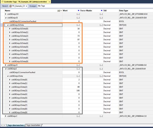
TR-Electronic GmbH
D-78647 Trossingen
Eglishalde 6
Tel.: (0049) 07425/228-0
Fax: (0049) 07425/228-33
email: info@tr-electronic.de
http://www.tr-electronic.de
Urheberrechtsschutz
Dieses Handbuch, einschließlich den darin enthaltenen Abbildungen, ist
urheberrechtlich geschützt. Drittanwendungen dieses Handbuchs, welche von den
urheberrechtlichen Bestimmungen abweichen, sind verboten. Die Reproduktion,
Übersetzung sowie die elektronische und fotografische Archivierung und Veränderung
bedarf der schriftlichen Genehmigung durch den Hersteller. Zuwiderhandlungen
verpflichten zu Schadenersatz.
Änderungsvorbehalt
Jegliche Änderungen, die dem technischen Fortschritt dienen, vorbehalten.
Dokumenteninformation
Ausgabe-/Rev.-Datum: 04/20/2021
Dokument-/Rev.-Nr.: TR-ECE-TI-DGB-0370 v01
Dateiname: TR-ECE-TI-DGB-0370-01.docx
Verfasser: KUC/DIR
Schreibweisen
Kursive oder fette Schreibweise steht für den Titel eines Dokuments oder wird zur
Hervorhebung benutzt.
Courier-Schrift zeigt Text an, der auf dem Bildschirm sichtbar ist und Software bzw.
Menüauswahlen von Software.
< > weist auf Tasten der Tastatur Ihres Computers hin (wie etwa ).
Marken
EtherNet/IP™, CIP™, CIP Safety™ und ODVA™ sind eingetragene Warenzeichen
der ODVA, Inc.
TR-Electronic GmbH 2021, All Rights Reserved Printed in the Federal Republic of Germany
Page 2 of 51 TR-ECE-TI-DGB-0370 v01 04/20/2021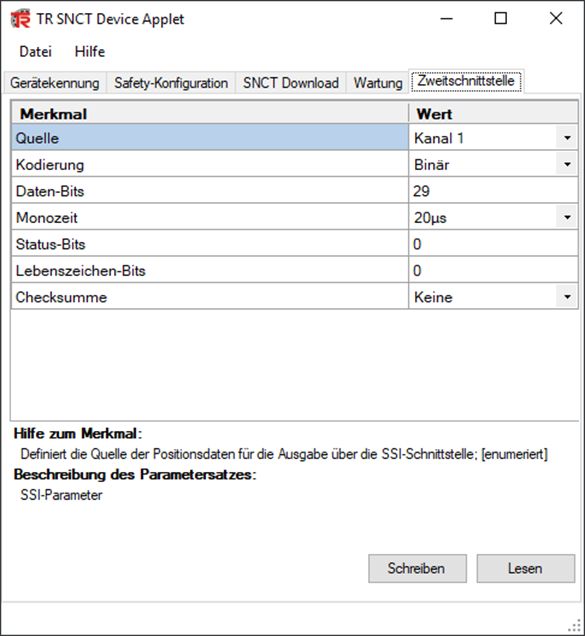
Inhaltsverzeichnis
Inhaltsverzeichnis .................................................................................................. 3
1 Allgemeines ......................................................................................................... 5
1.1 Geltungsbereich ...................................................................................................................... 5
1.2 Verwendete Abkürzungen / Begriffe ....................................................................................... 5
2 Sicherheitshinweise ............................................................................................ 6
2.1 Symbol- und Hinweis-Definition .............................................................................................. 6
2.2 Organisatorische Maßnahmen ............................................................................................... 6
2.3 Personalqualifikation............................................................................................................... 6
2.4 Nutzungsbedingungen der Softwarebeispiele ........................................................................ 7
3 Parametrierung / CRC Berechnung ................................................................... 8
3.1 Zweitschnittstelle parametrieren ............................................................................................. 9
4 Erstellung des Beispielprojekts ......................................................................... 11
4.1 Voraussetzungen .................................................................................................................... 11
4.2 Hardware Konfiguration .......................................................................................................... 12
4.3 Positionswerte als DINT ......................................................................................................... 20
4.4 Preset...................................................................................................................................... 21
5 Firmware Update ................................................................................................. 24
6 Software Download, Beispiele und Bibliotheken .............................................. 25
Printed in the Federal Republic of Germany TR-Electronic GmbH 2021, All Rights Reserved
04/20/2021 TR-ECE-TI-DGB-0370 v01 Page 3 of 51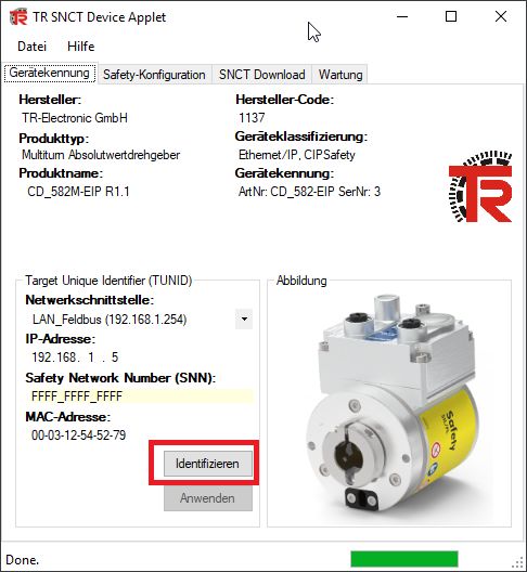
Inhaltsverzeichnis
Änderungs-Index
Änderung Datum Index
Erstausgabe 11.03.2021 00
Allgemeine Anpassungen
20.04.2021 01
Übersetzung eingebracht
TR-Electronic GmbH 2021, All Rights Reserved Printed in the Federal Republic of Germany
Page 4 of 51 TR-ECE-TI-DGB-0370 v01 04/20/2021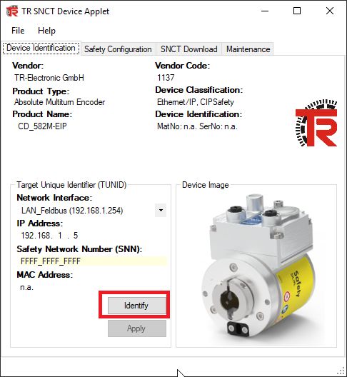
1 Allgemeines
Die vorliegende „Technische Information“ beinhaltet folgende Themen:
● Parametrierung / CRC Berechnung
● Erstellung eines Beispielprojekts
● Zugriff auf den sicherheitsgerichteten Datenkanal
Die „Technische Information“ kann separat angefordert werden.
1.1 Geltungsbereich
Diese „Technische Information“ gilt ausschließlich für folgende Mess-System-
Baureihen mit EtherNet/IP Schnittstelle und CIP Safety Profil in Verbindung mit einem
Rockwell Steuerungssystem Compact Guard Logix 1769-L33ERMS:
● CDV-582
● CDS-582
● CDH-582
Die Produkte sind durch aufgeklebte Typenschilder gekennzeichnet und sind
Bestandteil einer Anlage.
Es gelten somit zusammen folgende Dokumentationen:
● siehe Kapitel “Mitgeltende Dokumente” im Sicherheitshandbuch
www.tr-electronic.de/f/TR-ECE-BA-D-0142
● und diese optionale „Technische Information“
1.2 Verwendete Abkürzungen / Begriffe
Abkürzung / Begriff Erläuterung
SCID Safety Configuration Identifier
SIL Safety Integrity Level
SNCT Safety Network Configuration Tool
SNN Safety Network Number
TUNID Target Unique Network Identifier
Printed in the Federal Republic of Germany TR-Electronic GmbH 2021, All Rights Reserved
04/20/2021 TR-ECE-TI-DGB-0370 v01 Page 5 of 51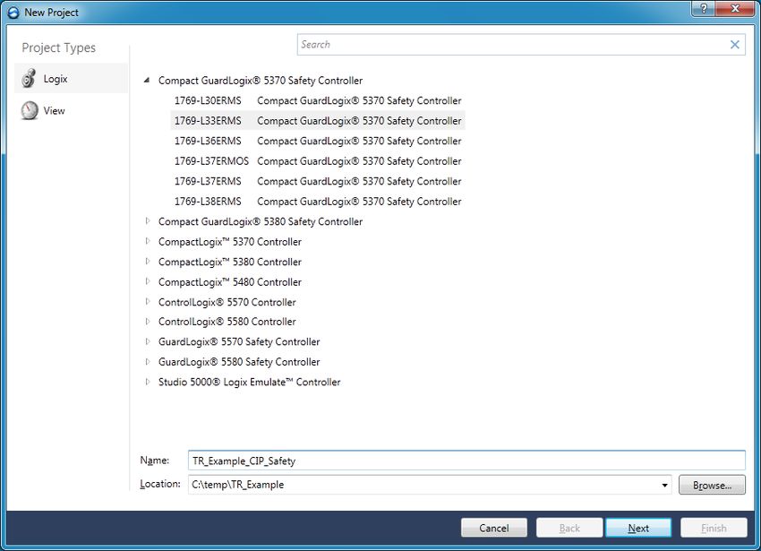
Sicherheitshinweise
2 Sicherheitshinweise
2.1 Symbol- und Hinweis-Definition
bedeutet, dass Tod oder schwere Körperverletzung eintreten
wird, wenn die entsprechenden Vorsichtsmaßnahmen nicht
getroffen werden.
bedeutet, dass Tod oder schwere Körperverletzung eintreten
kann, wenn die entsprechenden Vorsichtsmaßnahmen nicht
getroffen werden.
bedeutet, dass eine leichte Körperverletzung eintreten kann,
wenn die entsprechenden Vorsichtsmaßnahmen nicht
getroffen werden.
bedeutet, dass ein Sachschaden eintreten kann, wenn die
entsprechenden Vorsichtsmaßnahmen nicht getroffen
werden.
bezeichnet wichtige Informationen bzw. Merkmale und
Anwendungstipps des verwendeten Produkts.
2.2 Organisatorische Maßnahmen
Das mit Tätigkeiten am Mess-System beauftragte Personal muss vor Arbeitsbeginn das
Sicherheitshandbuch TR-ECE-BA-D-0142, insbesondere das Kapitel „Grundlegende
Sicherheitshinweise“, gelesen und verstanden haben.
2.3 Personalqualifikation
Die Konfiguration des Mess-Systems darf nur von qualifiziertem Fachpersonal
durchgeführt werden, siehe Studio 5000 Logix Designer – und
TR Sicherheitshandbuch.
TR-Electronic GmbH 2021, All Rights Reserved Printed in the Federal Republic of Germany
Page 6 of 51 TR-ECE-TI-DGB-0370 v01 04/20/2021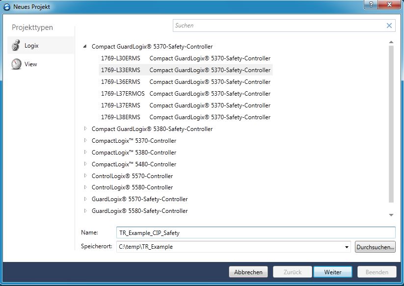
2.4 Nutzungsbedingungen der Softwarebeispiele
Für das fehlerfreie Funktionieren des Sicherheitsprogram-
mes und der Anwendungsbeispiele übernimmt die
TR-Electronic GmbH keine Haftung und keine Gewährleis-
tung.
Die zum Download angebotenen Softwarebeispiele dienen
ausschließlich zu Demonstrationszwecken, der Einsatz
durch den Anwender erfolgt auf eigene Gefahr.
Printed in the Federal Republic of Germany TR-Electronic GmbH 2021, All Rights Reserved
04/20/2021 TR-ECE-TI-DGB-0370 v01 Page 7 of 51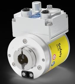
Parametrierung / CRC Berechnung
3 Parametrierung / CRC Berechnung
Die Rockwell Sicherheitssteuerung unterstützt Typ 1 und Typ 2 Safe Forward Open
Verbindungsframes. Das bedeutet, die SNN, SCID und die Funktionsparameter (z.B.
Zählrichtung) für das Mess-System werden vom Rockwell Steuerungssystem
eingestellt. Es ist keine vorherige Parametrierung der Safety-Konfiguration mit
dem SNCT notwendig.
Jedes CIP Safety Gerät merkt sich, von wem es parametriert
worden ist. Wurde das Mess-System mit dem SNCT
konfiguriert, so ist es der Rockwell-Steuerung nicht mehr
möglich, das Mess-System im Hochlauf zu parametrieren.
Eine Safety Forward Open Type 1 wird dann vom Mess-
System abgelehnt, da der Besitzer das SNCT ist. In diesem
Fall muss das Mess-System zurückgesetzt werden.
Dies gilt für die TUNID und für die Safety-Konfiguration.
Die Zweitschnittstelle ist hiervon nicht betroffen. Sie kann
immer mit dem SNCT parametriert werden.
Ein Rücksetzen des Mess-Systems kann auf zwei Arten durchgeführt werden:
- Mit Hilfe der Drehschalter (siehe Schnittstellen-Benutzerhandbuch)
- Mit Hilfe des SNCT (Button Rücksetzen):
Abbildung 1: TR SNCT Device Applet
Ein zurückgesetztes Mess-System hat die SNN FFFF_FFFF_FFFF.
TR-Electronic GmbH 2021, All Rights Reserved Printed in the Federal Republic of Germany
Page 8 of 51 TR-ECE-TI-DGB-0370 v01 04/20/2021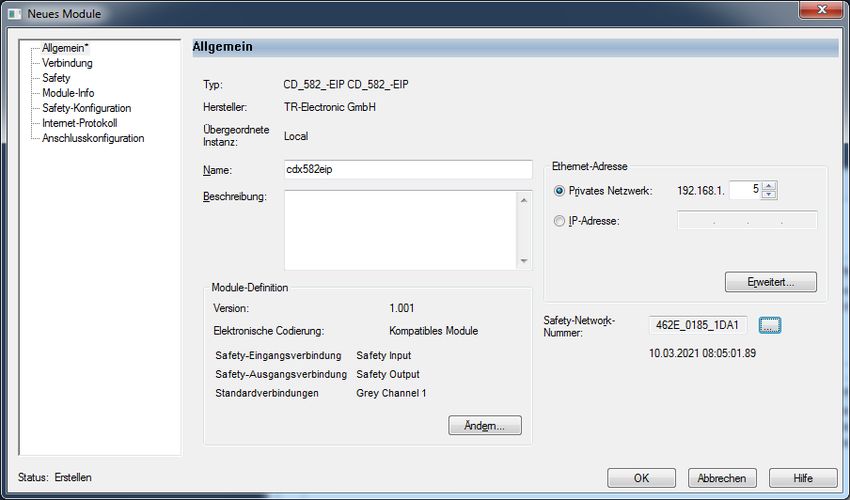
3.1 Zweitschnittstelle parametrieren
Lediglich die Zweitschnittstelle kann über das SNCT parametriert werden. Sie ist nicht
Teil der zyklischen Kommunikation und wird nur einmal konfiguriert.
Zuerst muss die IP-Adressen-Steuerung auf die entsprechende Adresse des Mess-
Systems eingestellt werden. Bei Verwendung der Drehschalter liegt die IP-Adresse im
Bereich von 192.168.1.1 bis 192.168.1.254.
Die Kommunikation mit dem Mess-System erfolgt über
TCP/IP, d.h. der PC, auf dem das SNCT läuft, muss sich über
eine Netzwerkkarte im gleichen IP-Adressbereich befinden
wie das Mess-System. (z.B. 192.168.1.100).
Mit Hilfe der Identifizieren-Schaltfläche kann die Verbindung zum Mess-System
überprüft werden (LEDs blinken).
Abbildung 2: TR SNCT Device Applet
Printed in the Federal Republic of Germany TR-Electronic GmbH 2021, All Rights Reserved
04/20/2021 TR-ECE-TI-DGB-0370 v01 Page 9 of 51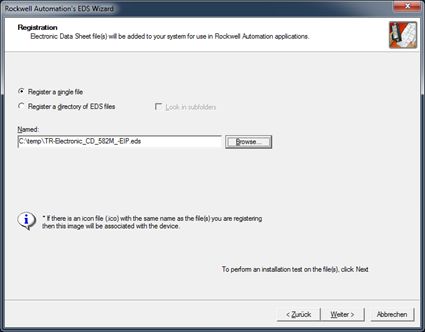
Parametrierung / CRC Berechnung
Falls das Mess-System eine Zweitschnittstelle besitzt wird der entsprechende Reiter
vom SNCT automatisch eingeblendet. Die Zweitschnittstellenparameter können hier
eingestellt werden:
Abbildung 3: TR SNCT Device Applet Zweitschnittstelle parametrieren
TR-Electronic GmbH 2021, All Rights Reserved Printed in the Federal Republic of Germany
Page 10 of 51 TR-ECE-TI-DGB-0370 v01 04/20/20214 Erstellung des Beispielprojekts
Dieses Kapitel beschreibt den Ablauf zur Erstellung des Beispielprojekts unter
Verwendung der integrierten Entwicklungsumgebungs-Software (IDE) von Rockwell
Studio5000 Logix Designer Version 32.00.00. Das Beispiel kann dazu
verwendet werden, um eine EtherNet/IP-Kommunikation mit TR Mess-Systemen
aufzubauen. Zwei Arten von Verbindungen werden dabei unterschieden:
- EtherNet/IP Verbindung (nicht sicherheitsgerichteter Positionswert,
auch „grauer Kanal“ genannt)
- EtherNet/IP mit CIP Safety Verbindung (sicherheitsgerichteter Positionswert)
4.1 Voraussetzungen
Gefahr der Außerkraftsetzung der fehlersicheren Funktion durch
unsachgemäße Projektierung des Sicherheitsprogramms!
Die Erstellung des Sicherheitsprogramms darf nur in Verbindung mit der
von Rockwell zur Software bzw. Hardware mitgelieferten System-
dokumentation erfolgen.
Nachfolgende Beschreibungen beziehen sich auf den reinen Ablauf,
ohne dabei die Hinweise aus dem Rockwell-Handbuch mit zu
berücksichtigen.
Die im Rockwell-Handbuch gegebenen Informationen, Hinweise,
insbesondere die Sicherheitshinweise und Warnungen, sind daher
zwingend zu beachten und einzuhalten.
Die aufgezeigte Projektierung ist als Beispiel aufzufassen. Der
Anwender ist daher verpflichtet, die Verwendbarkeit der Projektierung
für seine Applikation zu überprüfen und anzupassen. Dazu gehören
auch die Auswahl der geeigneten sicherheitsgerichteten Hard-
warekomponenten, sowie die notwendigen Softwarevoraussetzungen.
Für das Projektbeispiel verwendete Softwarekomponenten:
● Studio5000 Logix Designer Version 32.00.00
Für das Projektbeispiel verwendete Hardware-Komponenten:
● Compact Guard Logix (1769-L33ERMS) von Rockwell Automation
Technologies
● CDS582-10035 Sicherheits - Mess-System von TR-Electronic
Printed in the Federal Republic of Germany TR-Electronic GmbH 2021, All Rights Reserved
04/20/2021 TR-ECE-TI-DGB-0370 v01 Page 11 of 51Erstellung des Beispielprojekts
4.2 Hardware Konfiguration
Studio 5000 starten und ein Neues Projekt anlegen. Nachdem die richtige
SPS ausgewählt wurde und der Name vergeben wurde, mit Weiter fortfahren:
Abschluss der Anlage des neuen Projektes mit Beenden. Es wird im Beispiel kein
Schutz definiert:
TR-Electronic GmbH 2021, All Rights Reserved Printed in the Federal Republic of Germany
Page 12 of 51 TR-ECE-TI-DGB-0370 v01 04/20/2021 In der Menüleiste unter EXTRAS das EDS-Hardware-Installations-Tool
starten:
Im EDS Wizard Register a single file auswählen und die
Gerätebeschreibung von TR auswählen:
Weiter, bis zur endgültigen Installation
Printed in the Federal Republic of Germany TR-Electronic GmbH 2021, All Rights Reserved
04/20/2021 TR-ECE-TI-DGB-0370 v01 Page 13 of 51Erstellung des Beispielprojekts
Im Projekt mit Rechtsklick auf Ethernet und Neues Module… auswählen:
TR-Electronic Mess-System hinzufügen:
Mit Klick auf den Button Erstellen wird das Gerät hinzugefügt und kann
parametriert werden.
TR-Electronic GmbH 2021, All Rights Reserved Printed in the Federal Republic of Germany
Page 14 of 51 TR-ECE-TI-DGB-0370 v01 04/20/2021Zunächst wird ein Name und eine IP-Adresse vergeben, die SNN wird automatisch
erstellt. Einstellungen anschließend über OK bestätigen.
Fenster Modultyp auswählen schließen.
Die Parametrierung des Mess-Systems kann nun jederzeit im Projekt über einen
Doppelklick auf das Mess-System geändert werden. Alternativ kann die
Parametrierung auch über die rechte Maustaste -> Eigenschaften
vorgenommen werden.
Im Fenster Neues Module unter Module-Definition den Button Ändern
klicken -> im Fenster Module-Definition das Modul TR Grey Channel 1
auswählen und mit OK bestätigen:
Printed in the Federal Republic of Germany TR-Electronic GmbH 2021, All Rights Reserved
04/20/2021 TR-ECE-TI-DGB-0370 v01 Page 15 of 51Erstellung des Beispielprojekts
Unter Verbindung können die Standardwerte für den Test belassen werden:
Unter Safety können die Standardwerte ebenfalls belassen werden:
Unter Safety-Konfiguration werden die sicheren Parameter für das Mess-
System eingestellt:
Es muss beachtet werden, dass hier der SIL Level auf SIL2
eingestellt werden muss, falls es sich um einen SIL2-Mess-
System handelt (siehe Typenschild). Ein SIL2-Mess-System
läuft nicht mit einem SIL3-Parametersatz an.
TR-Electronic GmbH 2021, All Rights Reserved Printed in the Federal Republic of Germany
Page 16 of 51 TR-ECE-TI-DGB-0370 v01 04/20/2021 Die Moduleigenschaften können nun mit OK geschlossen werden
Die grauen Parameter können mit Doppelklick auf den Eintrag Steuerungs-Tags
eingestellt werden:
Im Reiter Tags überwachen -> cdx582eip:C können die grauen Parameter
vergeben werden:
Printed in the Federal Republic of Germany TR-Electronic GmbH 2021, All Rights Reserved
04/20/2021 TR-ECE-TI-DGB-0370 v01 Page 17 of 51Erstellung des Beispielprojekts
Das Projekt kann jetzt bereits generiert und an die SPS übertragen werden. Die
SPS ist im vorliegenden Fall via USB mit dem PC verbunden. Zur Übertragung
vom Offline-Modus zu Herunterladen wechseln:
Im nächsten Fenster Herunterladen klicken. Hierbei muss sich der
Schlüsselschalter in Position PROG befinden:
TR-Electronic GmbH 2021, All Rights Reserved Printed in the Federal Republic of Germany
Page 18 of 51 TR-ECE-TI-DGB-0370 v01 04/20/2021 Nach dem Download und dem Anschluss des Mess-Systems an Port 1 der
Steuerung, läuft das Mess-System direkt an und es können die grauen und
sicheren Istwerte bereits im Studio5000 unter den Steuerungs-Tags betrachtet
werden (orange=sichere Eingangswerte; grau=graue Eingangswerte):
Printed in the Federal Republic of Germany TR-Electronic GmbH 2021, All Rights Reserved
04/20/2021 TR-ECE-TI-DGB-0370 v01 Page 19 of 51Erstellung des Beispielprojekts
4.3 Positionswerte als DINT
Da der Logix Designer von Rockwell es Fremdgeräten nicht ermöglicht, die
zyklischen Daten in explizite Datentypen zu wandeln, z.B. den Positionswert als DINT,
muss dies manuell durchgeführt werden. Dafür müssen bei den Steuerungs-Tags zwei
neue Einträge vom Typ DINT angelegt werden: Position_safe und
Position_grey:
Für den grauen Istwert muss die bereits vorhandene Main-Routine unter
Tasks/MainTask/MainProgram/MainRoutine um folgende Zeile erweitert werden:
Für den sicheren Istwert muss die bereits vorhandene sichere Main-Routine unter
Tasks/SafetyTask/SafetyProgram/MainRoutine um folgende Zeile erweitert werden:
Nach einem erneuten Download des Projektes können jetzt die Positionsistwerte in den
Steuerungs-Tags betrachten werden. Hierbei muss der Schlüsselschalter nach dem
Download auf RUN gestellt werden!:
TR-Electronic GmbH 2021, All Rights Reserved Printed in the Federal Republic of Germany
Page 20 of 51 TR-ECE-TI-DGB-0370 v01 04/20/20214.4 Preset
Der Preset wird mit Hilfe der Control- und Statuswörter durchgeführt. Im vorliegenden
Beispiel stellt TR den prinzipiellen Ablauf des Presets anhand eines Beispiels (SAFE-
Routine TR_Preset; Sprache: LD (=Ladder Diagram)) dar.
Die Routine TR_Preset kann unter dem SafetyProgram selbst erstellt werden oder
aus dem Beispielprojekt von TR exportiert werden und im eigenen Projekt wieder
importiert werden.
Abbildung 4: Preset-Routine aus Beispiel exportieren
Nachdem die Preset-Routine im Projekt eingefügt ist, muss diese zyklisch aufgerufen
werden. Darum wird die MainRoutine im SafetyTask um einen JSR-Aufruf erweitert,
um die Preset-Routine anzuspringen:
Printed in the Federal Republic of Germany TR-Electronic GmbH 2021, All Rights Reserved
04/20/2021 TR-ECE-TI-DGB-0370 v01 Page 21 of 51Erstellung des Beispielprojekts
Im Anschluss wird das Projekt gespeichert und erneut heruntergeladen. Hierbei muss
sich der Schlüsselschalter in Stellung PROG befinden.
Nach dem Download wird der Schlüsselschalter wieder auf RUN gestellt. Durch Setzen
der Variablen start_preset_tag kann der Preset-Vorgang gestartet werden. Er wird
automatisch wieder beendet, wenn die Preset-Status-Bits preset_in_ok oder
preset_in_error gesetzt werden.
TR-Electronic GmbH 2021, All Rights Reserved Printed in the Federal Republic of Germany
Page 22 of 51 TR-ECE-TI-DGB-0370 v01 04/20/2021Der Preset-Ablauf kann nur durchgeführt werden, wenn die sichere
Eingangsverbindung und die sichere Ausgangsverbindung projektiert und aufgebaut
sind (Executing).
Das Preset-Beispiel kann bei einer aktiven Verbindung zur Steuerung visuell
nachvollzogen werden. In grün gehaltene Objekte sind aktiv:
Printed in the Federal Republic of Germany TR-Electronic GmbH 2021, All Rights Reserved
04/20/2021 TR-ECE-TI-DGB-0370 v01 Page 23 of 51Firmware Update
5 Firmware Update
Wenn ein Update der Mess-System Firmware erforderlich ist, stellt TR-Electronic
Update-Dateien zur Verfügung, die speziell für die Mess-Systeme, die ein Update
benötigen, erstellt werden. Mit Hilfe des Tools TR SNCT Device Applet ist es
möglich, die Dateien für das Update an das Mess-System zu übertragen.
Die Kommunikation zum Mess-System erfolgt über TCP/IP,
so dass der PC, auf dem das SNCT-Tool läuft, über eine
Netzwerkkarte im gleichen IP-Adressbereich wie das Mess-
System verfügen muss (z.B. 192.168.1.100).
Auf Wunsch kann TR-Electronic den Kunden auch unterstützen, wenn ein Update
benötigt wird.
TR-Electronic GmbH 2021, All Rights Reserved Printed in the Federal Republic of Germany
Page 24 of 51 TR-ECE-TI-DGB-0370 v01 04/20/20216 Software Download, Beispiele und Bibliotheken
EDS Datei:
www.tr-electronic.de/f/TR-ECE-ID-MUL-0067
Software TR SNCT Device Applet für die CRC Berechnung:
www.tr-electronic.com/f/zip/TR-ECE-SW-MUL-0016
Dokumentation TR SNCT Device Applet
www.tr-electronic.de/f/TR-ECE-TI-DGB-0364
Beispielprojekt für Rockwell Steuerung:
https://www.tr-electronic.de/f/zip/TR-ECE-SW-MUL-0019
Printed in the Federal Republic of Germany TR-Electronic GmbH 2021, All Rights Reserved
04/20/2021 TR-ECE-TI-DGB-0370 v01 Page 25 of 51Software Download, Beispiele und Bibliotheken TR-Electronic GmbH 2021, All Rights Reserved Printed in the Federal Republic of Germany Page 26 of 51 TR-ECE-TI-DGB-0370 v01 04/20/2021
Absolute Encoder CD_582_-EIP
EtherNet/IP / CIP Safety
Parameterization with ROCKWELL control system
Compact Guard Logix (1769-L33ERMS)
CDV582
CDS582 / CDH582
Stock photo
_Safety Program Creation
_Configuration Example
_Access to the safety-oriented data channel Technical
_Parameter Definition / CRC Calculation Information
Printed in the Federal Republic of Germany TR-Electronic GmbH 2021, All Rights Reserved
04/20/2021 TR-ECE-TI-DGB-0370 v01 Page 27 of 51TR-Electronic GmbH
D-78647 Trossingen
Eglishalde 6
Tel.: (0049) 07425/228-0
Fax: (0049) 07425/228-33
email: info@tr-electronic.de
http://www.tr-electronic.de
Copyright protection
This Manual, including the illustrations contained therein, is subject to copyright
protection. Use of this Manual by third parties in contravention of copyright regulations
is not permitted. Reproduction, translation as well as electronic and photographic
archiving and modification require the written content of the manufacturer. Violations
shall be subject to claims for damages.
Subject to modifications
The right to make any changes in the interest of technical progress is reserved.
Document information
Release date / Rev. date: 04/20/2021
Document / Rev. no.: TR-ECE-TI-DGB-0370 v01
File name: TR-ECE-TI-DGB-0370-01.docx
Author: KUC/DIR
Font styles
Italic or bold font styles are used for the title of a document or are used for highlighting.
Courier font displays text, which is visible on the display or screen and software
menu selections.
< > indicates keys on your computer keyboard (such as ).
Brand names
EtherNet/IP™, CIP™, CIP Safety™ and ODVA™ are trademarks of ODVA, Inc.
TR-Electronic GmbH 2021, All Rights Reserved Printed in the Federal Republic of Germany
Page 28 of 51 TR-ECE-TI-DGB-0370 v01 04/20/2021Contents
Contents .................................................................................................................. 29
1 General information ............................................................................................ 31
1.1 Applicability ............................................................................................................................. 31
1.2 Abbreviations / terms used ..................................................................................................... 31
2 Safety information ............................................................................................... 32
2.1 Definition of symbols and notes .............................................................................................. 32
2.2 Organizational measures ........................................................................................................ 32
2.3 Personnel qualification............................................................................................................ 32
2.4 Conditions of use for software examples ................................................................................ 33
3 Parameterization / CRC calculation ................................................................... 34
3.1 Parameterizing the second interface ...................................................................................... 35
4 Example project creation .................................................................................... 37
4.1 Prerequisites ........................................................................................................................... 37
4.2 Hardware configuration........................................................................................................... 38
4.3 Position values as DINT ......................................................................................................... 46
4.4 Preset...................................................................................................................................... 47
5 Firmware update .................................................................................................. 50
6 Download of software, examples and libraries ................................................. 51
Printed in the Federal Republic of Germany TR-Electronic GmbH 2021, All Rights Reserved
04/20/2021 TR-ECE-TI-DGB-0370 v01 Page 29 of 51Contents
Revision index
Revision Date Index
First release 03/11/2021 00
General modifications
04/20/2021 01
Translation added
TR-Electronic GmbH 2021, All Rights Reserved Printed in the Federal Republic of Germany
Page 30 of 51 TR-ECE-TI-DGB-0370 v01 04/20/20211 General information
This "Technical Information" includes the following topics:
● Parameter definition / CRC calculation
● Example project creation
● Access to the safety-oriented data channel
The "Technical Information" can be requested separately.
1.1 Applicability
This "Technical Information" applies exclusively for the following measuring system
series with EtherNet/IP interface and CIP Safety profile in conjunction with a Rockwell
Control System Compact Guard Logix 1769-L33ERMS:
● CDV-582
● CDS-582
● CDH-582
The products are labeled with affixed nameplates and are components of a system.
The following documentation therefore also applies:
● see chapter “Other applicable documents” in the Safety Manual
www.tr-electronic.de/f/TR-ECE-BA-GB-0142
● and this optional "Technical Information"
1.2 Abbreviations / terms used
Abbreviation / Term Explanation
SCID Safety Configuration Identifier
SIL Safety Integrity Level
SNCT Safety Network Configuration Tool
SNN Safety Network Number
TUNID Target Unique Network Identifier
Printed in the Federal Republic of Germany TR-Electronic GmbH 2021, All Rights Reserved
04/20/2021 TR-ECE-TI-DGB-0370 v01 Page 31 of 51Safety information
2 Safety information
2.1 Definition of symbols and notes
means that death or serious injury will occur if the required
precautions are not met.
means that death or serious injury can occur if the required
precautions are not met.
means that minor injuries can occur if the required
precautions are not met.
means that damage to property can occur if the required
precautions are not met.
indicates important information or features and application
tips for the product used.
2.2 Organizational measures
Prior to commencing work, personnel working with the measuring system must have
read and understood the Safety Manual TR-ECE-BA-GB-0142, particularly the chapter
"Basic safety instructions".
2.3 Personnel qualification
The configuration of the measuring system must be carried out by qualified personnel
only, see manual of Studio 5000 Logix Designer – and TR Safety Manual.
TR-Electronic GmbH 2021, All Rights Reserved Printed in the Federal Republic of Germany
Page 32 of 51 TR-ECE-TI-DGB-0370 v01 04/20/20212.4 Conditions of use for software examples
TR-Electronic GmbH cannot accept any liability or guarantee
for error-free functioning of the safety program and
application examples.
The software examples available for download serve
exclusively for demonstration purposes; they are used at the
user's own risk.
Printed in the Federal Republic of Germany TR-Electronic GmbH 2021, All Rights Reserved
04/20/2021 TR-ECE-TI-DGB-0370 v01 Page 33 of 51Parameterization / CRC calculation
3 Parameterization / CRC calculation
The Rockwell safety control system supports Type 1 and Type 2 Safe Forward Open
connection frames. This means that the SNN, SCID and the function parameters
(e.g. counting direction) for the measuring system are set by the Rockwell control
system. No prior parameterization of the safety configuration with the SNCT is
necessary.
Each CIP Safety device remembers by which device it has
been parameterized. If the measuring system has been
configured with the SNCT, it is no longer possible for the
Rockwell controller to parameterize the measuring system
during startup. A Safety Forward Open Type 1 is then rejected
by the measuring system because the owner is the SNCT. In
this case, the measuring system must be reset.
This applies to the TUNID and to the safety
configuration. The secondary interface is not affected by
this. It can always be parameterized with the SNCT.
A reset of the measuring system can be performed in two ways:
- With the help of the rotary switches (see Interface Manual)
- With the help of the SNCT (Button Reset):
Figure 1: TR SNCT Device Applet
A reset measuring system has the SNN FFFF_FFFF_FFFF.
TR-Electronic GmbH 2021, All Rights Reserved Printed in the Federal Republic of Germany
Page 34 of 51 TR-ECE-TI-DGB-0370 v01 04/20/20213.1 Parameterizing the second interface
The secondary interface has to be parameterized via the SNCT. It is not part of the cyclic
communication and is configured only once.
First, the IP address control must be set to the corresponding address of the measuring
system. When using the rotary switches, the IP address is in the range from 192.168.1.1
to 192.168.1.254.
Communication with the measuring system takes place via
TCP/IP, i.e. the PC on which the SNCT is running must be
located in the same IP address range as the measuring
system via a network card (e.g. 192.168.1.100).
The Identify button can be used to check the connection to the measuring system
(LEDs flash).
Figure 2: TR SNCT Device Applet
Printed in the Federal Republic of Germany TR-Electronic GmbH 2021, All Rights Reserved
04/20/2021 TR-ECE-TI-DGB-0370 v01 Page 35 of 51Parameterization / CRC calculation
If the measuring system has a secondary interface, the corresponding tab is
automatically displayed by the SNCT. The secondary interface parameters can be set
here:
Figure 3: TR SNCT Device Applet: Parameterize second interface
TR-Electronic GmbH 2021, All Rights Reserved Printed in the Federal Republic of Germany
Page 36 of 51 TR-ECE-TI-DGB-0370 v01 04/20/20214 Example project creation
This chapter describes the procedure for creating the example project using Rockwell´s
Integrated Development Environment (IDE) software Studio5000 Logix Designer
Version 32.00.00. The example can be used to start an EtherNet/IP-communication
with the TR-encoders with two kinds of connections:
- EtherNet/IP connection (non-safety-related position value,
also called “grey channel”)
- EtherNet/IP with CIP Safety connection (safety-related position value)
4.1 Prerequisites
Danger of deactivation of the fail-safe function through incorrect
configuration of the safety program!
The safety program must only be created in conjunction with the system
documentation provided by Rockwell for the software and hardware.
The following descriptions relate to the pure procedure and do not take
account of the instructions from the Rockwell manual.
It is therefore essential to observe and comply with the information and
instructions provided in the Rockwell manual, particularly the safety
instructions and warnings.
The configuration shown should be taken as an example. The user is
required to check and adapt the usability of the configuration for his own
application. This also includes the selection of suitable safety-oriented
hardware components and the necessary software prerequisites.
Software components used for the project example:
● Studio5000 Logix Designer Version 32.00.00
Hardware components in the project example:
● Compact Guard Logix (1769-L33ERMS) of Rockwell Automation Technologies
● CDS582-10035: Safety - measuring system from TR-Electronic
Printed in the Federal Republic of Germany TR-Electronic GmbH 2021, All Rights Reserved
04/20/2021 TR-ECE-TI-DGB-0370 v01 Page 37 of 51Example project creation
4.2 Hardware configuration
Start Studio 5000 and create a New Project. After the correct PLC has been
selected and the name has been assigned, continue with Next:
Completion of the creation of the new project with Finish. No protection is defined
in the example:
TR-Electronic GmbH 2021, All Rights Reserved Printed in the Federal Republic of Germany
Page 38 of 51 TR-ECE-TI-DGB-0370 v01 04/20/2021 Choose TOOLS in the menu bar and start the EDS Hardware Installation
Tool:
Choose Register a single file in the EDS Wizard and choose the
TR device description file:
Click Next, until the final installation
Printed in the Federal Republic of Germany TR-Electronic GmbH 2021, All Rights Reserved
04/20/2021 TR-ECE-TI-DGB-0370 v01 Page 39 of 51Example project creation
In the project: right-click on Ethernet and select New Module… :
Add TR-Electronic measuring system:
By clicking the Create button, the device is added and can be parameterized.
TR-Electronic GmbH 2021, All Rights Reserved Printed in the Federal Republic of Germany
Page 40 of 51 TR-ECE-TI-DGB-0370 v01 04/20/2021First, a Name and an IP Address are assigned, the SNN is created automatically. Then
confirm the settings via OK.
Close window Select Module Type.
The parameterization of the measuring system can now be changed at any time in
the project by double-clicking on the measuring system. Alternatively, the
parameterization can also be made via the right mouse button -> Properties.
In the New Module window under Module Definition click the Change button
-> in the Module Definition window select the TR Grey Channel 1 module
and confirm with OK:
Printed in the Federal Republic of Germany TR-Electronic GmbH 2021, All Rights Reserved
04/20/2021 TR-ECE-TI-DGB-0370 v01 Page 41 of 51Example project creation
Under Connection, the default values for the test can be retained:
Under Safety, the default values can be retained also:
Under Safety Configuration the safe parameters for the measuring system
are set:
It must be noted that the SIL level must be set to SIL2 here if
it is a SIL2 measuring system (see type plate). A SIL2
measuring system does not start with a SIL3 parameter set.
TR-Electronic GmbH 2021, All Rights Reserved Printed in the Federal Republic of Germany
Page 42 of 51 TR-ECE-TI-DGB-0370 v01 04/20/2021 The module properties can now be closed with OK
The grey parameters can be set by double-clicking on the Controller Tags
entry:
In the tab Monitor Tags -> cdx582eip:C the grey parameters can be assigned:
Printed in the Federal Republic of Germany TR-Electronic GmbH 2021, All Rights Reserved
04/20/2021 TR-ECE-TI-DGB-0370 v01 Page 43 of 51Example project creation
The project is ready to be transferred to the PLC now. In this case, the PLC is
connected to the PC via USB. Switch from Offline Mode to Download for
transfer:
In the next window click Download. The key switch must be in the PROG position:
TR-Electronic GmbH 2021, All Rights Reserved Printed in the Federal Republic of Germany
Page 44 of 51 TR-ECE-TI-DGB-0370 v01 04/20/2021 After downloading and connecting the measuring system to port 1 of the controller,
the measuring system starts directly and the grey and safe actual values can
already be viewed in the Studio5000 under the controller tags (orange=safe input
values; grey=grey input values):
Printed in the Federal Republic of Germany TR-Electronic GmbH 2021, All Rights Reserved
04/20/2021 TR-ECE-TI-DGB-0370 v01 Page 45 of 51Example project creation
4.3 Position values as DINT
Since the Logix Designer from Rockwell does not allow third-party devices to
convert the cyclic data into explicit data types, e.g. the position value as DINT, this must
be done manually. For this, two new entries of type DINT have to be created at the
controller tags: Position_safe and Position_grey:
For the grey actual value, the following line must be added to the already existing
MainRoutine under Tasks/MainTask/MainProgram/MainRoutine:
For the safe actual value, the following line must be added to the already existing safe
MainRoutine under Tasks/SafetyTask/SafetyProgram/MainRoutine:
After a renewed download of the project, the position actual values can now be viewed
in the controller tags. Here the key switch must be set to RUN after the download!
TR-Electronic GmbH 2021, All Rights Reserved Printed in the Federal Republic of Germany
Page 46 of 51 TR-ECE-TI-DGB-0370 v01 04/20/20214.4 Preset
The preset is executed with the help of the control and status words. In this example,
TR illustrates the principle sequence of the preset by means of an example
(SAFE-Routine TR_Preset; language: LD (=Ladder Diagram)).
The routine TR_Preset has to be created under the SafetyProgram by the customer.
To get started it is possible to test the Preset-function of the TR-example-project by
importing it into the customer’s project after exporting it out of the TR-example-project.
Figure 4: Export preset routine from example
After the preset routine has been inserted in the project, it must be called cyclically.
Therefore, the MainRoutine in the SafetyTask is extended by a JSR call to start the
preset routine:
Printed in the Federal Republic of Germany TR-Electronic GmbH 2021, All Rights Reserved
04/20/2021 TR-ECE-TI-DGB-0370 v01 Page 47 of 51Example project creation
The project is then saved and downloaded again. The key switch must be in the PROG
position.
After the download the key switch has to be set to RUN again. By setting the variable
start_preset_tag the preset process can be started. It is automatically finished
again when the preset status bits preset_in_ok or preset_in_error are set.
TR-Electronic GmbH 2021, All Rights Reserved Printed in the Federal Republic of Germany
Page 48 of 51 TR-ECE-TI-DGB-0370 v01 04/20/2021The preset procedure can only be executed if the safe input connection and the safe
output connection are configured and established (Executing).
The preset example can be visually reproduced with an active connection to the
controller. Objects kept in green are active:
Printed in the Federal Republic of Germany TR-Electronic GmbH 2021, All Rights Reserved
04/20/2021 TR-ECE-TI-DGB-0370 v01 Page 49 of 51Firmware update
5 Firmware update
If an update of the measuring system firmware is required, TR-Electronic provides
update files that are created specifically for the measuring systems that require an
update. With the help of the tool TR SNCT Device Applet it is possible to transfer
the files for the update to the measuring system.
Communication to the measuring system takes place via
TCP/IP, so the PC running the SNCT tool must have a
network card in the same IP address range as the measuring
system (e.g. 192.168.1.100).
If requested, TR-Electronic can also support the customer when an update is needed.
TR-Electronic GmbH 2021, All Rights Reserved Printed in the Federal Republic of Germany
Page 50 of 51 TR-ECE-TI-DGB-0370 v01 04/20/20216 Download of software, examples and libraries
EDS file:
www.tr-electronic.de/f/TR-ECE-ID-MUL-0067
Software TR SNCT Device Applet for the CRC calculation:
www.tr-electronic.com/f/zip/TR-ECE-SW-MUL-0016
Documentation TR SNCT Device Applet
www.tr-electronic.de/f/TR-ECE-TI-DGB-0364
Example project for Rockwell control:
https://www.tr-electronic.de/f/zip/TR-ECE-SW-MUL-0019
Printed in the Federal Republic of Germany TR-Electronic GmbH 2021, All Rights Reserved
04/20/2021 TR-ECE-TI-DGB-0370 v01 Page 51 of 51Sie können auch lesen