Absolut Encoder CD_582_-EIP EtherNet/IP / CIP Safety
←
→
Transkription von Seiteninhalten
Wenn Ihr Browser die Seite nicht korrekt rendert, bitte, lesen Sie den Inhalt der Seite unten
D Seite 1 - 23
GB Page 25 - 47
Absolut Encoder CD_582_-EIP
EtherNet/IP / CIP Safety
Parametrierung mit SCHNEIDER Steuerungssystem
M580 SIL3 (BME P58)
Notice: This PDF is not subject to an updating service
Get the most recent version:
https://www.tr-electronic.de/f/TR-ECE-TI-DGB-0363
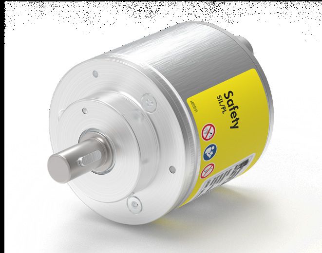
CDV582
CDS582 / CDH582
Abbildungen ähnlich
TR-ECE-TI-DGB-0363 v00 01/31/2020
_Sicherheitsprogramm erstellen
_Konfigurationsbeispiel
_Zugriff auf den sicherheitsgerichteten Datenkanal
_Parametrierung / CRC Berechnung
Technische
Information
TR-Electronic GmbH
D-78647 Trossingen
Eglishalde 6
Tel.: (0049) 07425/228-0
Fax: (0049) 07425/228-33
email: info@tr-electronic.de
http://www.tr-electronic.de
Urheberrechtsschutz
Dieses Handbuch, einschließlich den darin enthaltenen Abbildungen, ist
urheberrechtlich geschützt. Drittanwendungen dieses Handbuchs, welche von den
urheberrechtlichen Bestimmungen abweichen, sind verboten. Die Reproduktion,
Übersetzung sowie die elektronische und fotografische Archivierung und Veränderung
bedarf der schriftlichen Genehmigung durch den Hersteller. Zuwiderhandlungen
verpflichten zu Schadenersatz.
Änderungsvorbehalt
Jegliche Änderungen, die dem technischen Fortschritt dienen, vorbehalten.
Dokumenteninformation
Ausgabe-/Rev.-Datum: 01/31/2020
Dokument-/Rev.-Nr.: TR-ECE-TI-DGB-0363 v00
Dateiname: TR-ECE-TI-DGB-0363-00.docx
Verfasser: KUC/DIR
Schreibweisen
Kursive oder fette Schreibweise steht für den Titel eines Dokuments oder wird zur
Hervorhebung benutzt.
Courier-Schrift zeigt Text an, der auf dem Bildschirm sichtbar ist und Software bzw.
Menüauswahlen von Software.
″< > ″ weist auf Tasten der Tastatur Ihres Computers hin (wie etwa ).
Marken
EtherNet/IP™, CIP™, CIP Safety™ und ODVA™ sind eingetragene Warenzeichen
der ODVA, Inc.
TR-Electronic GmbH 2020, All Rights Reserved Printed in the Federal Republic of Germany
Page 2 of 47 TR-ECE-TI-DGB-0363 v00 01/31/2020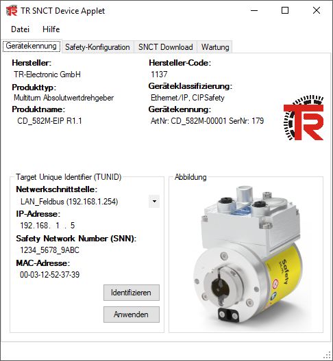
Inhaltsverzeichnis
Inhaltsverzeichnis .................................................................................................. 3
1 Allgemeines ......................................................................................................... 5
1.1 Geltungsbereich ...................................................................................................................... 5
2 Sicherheitshinweise ............................................................................................ 6
2.1 Symbol- und Hinweis-Definition .............................................................................................. 6
2.2 Organisatorische Maßnahmen ............................................................................................... 6
2.3 Personalqualifikation............................................................................................................... 6
2.4 Nutzungsbedingungen der Softwarebeispiele ........................................................................ 7
3 Parametrierung / CRC Berechnung ................................................................... 8
4 Erstellung des Beispielprojekts ......................................................................... 11
4.1 Voraussetzungen .................................................................................................................... 11
4.2 Hardware Konfiguration .......................................................................................................... 12
4.3 Projekt generieren und übertragen ......................................................................................... 20
5 Firmware Update ................................................................................................. 22
6 Software Download, Beispiele und Bibliotheken .............................................. 23
Printed in the Federal Republic of Germany TR-Electronic GmbH 2020, All Rights Reserved
01/31/2020 TR-ECE-TI-DGB-0363 v00 Page 3 of 47
Inhaltsverzeichnis Änderungs-Index Änderung Datum Index Erstausgabe 31.01.2020 00 TR-Electronic GmbH 2020, All Rights Reserved Printed in the Federal Republic of Germany Page 4 of 47 TR-ECE-TI-DGB-0363 v00 01/31/2020
1 Allgemeines
Die vorliegende „Technische Information“ beinhaltet folgende Themen:
● Parametrierung / CRC Berechnung
● Erstellung eines Beispielprojekts
● Zugriff auf den sicherheitsgerichteten Datenkanal
Die „Technische Information“ kann separat angefordert werden.
1.1 Geltungsbereich
Diese „Technische Information“ gilt ausschließlich für folgende Mess-System-
Baureihen mit EtherNet/IP Schnittstelle und CIP Safety Profil in Verbindung mit
einem SCHNEIDER Steuerungssystem M580S:
● CDV-582
● CDS-582
● CDH-582
Die Produkte sind durch aufgeklebte Typenschilder gekennzeichnet und sind
Bestandteil einer Anlage.
Es gelten somit zusammen folgende Dokumentationen:
● siehe Kapitel “Mitgeltende Dokumente” im Sicherheitshandbuch
www.tr-electronic.de/f/TR-ECE-BA-D-0142
● und diese optionale „Technische Information“
Printed in the Federal Republic of Germany TR-Electronic GmbH 2020, All Rights Reserved
01/31/2020 TR-ECE-TI-DGB-0363 v00 Page 5 of 47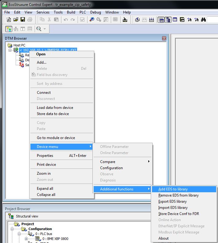
Sicherheitshinweise
2 Sicherheitshinweise
2.1 Symbol- und Hinweis-Definition
bedeutet, dass Tod oder schwere Körperverletzung
eintreten wird, wenn die entsprechenden
Vorsichtsmaßnahmen nicht getroffen werden.
bedeutet, dass Tod oder schwere Körperverletzung
eintreten kann, wenn die entsprechenden
Vorsichtsmaßnahmen nicht getroffen werden.
bedeutet, dass eine leichte Körperverletzung eintreten kann,
wenn die entsprechenden Vorsichtsmaßnahmen nicht
getroffen werden.
bedeutet, dass ein Sachschaden eintreten kann, wenn die
entsprechenden Vorsichtsmaßnahmen nicht getroffen
werden.
bezeichnet wichtige Informationen bzw. Merkmale und
Anwendungstipps des verwendeten Produkts.
2.2 Organisatorische Maßnahmen
Das mit Tätigkeiten am Mess-System beauftragte Personal muss vor Arbeitsbeginn
das Sicherheitshandbuch TR-ECE-BA-D-0142, insbesondere das Kapitel
„Grundlegende Sicherheitshinweise“, gelesen und verstanden haben.
2.3 Personalqualifikation
Die Konfiguration des Mess-Systems darf nur von qualifiziertem Fachpersonal
durchgeführt werden, siehe Control Expert - und SNCT - Dokumentation.
TR-Electronic GmbH 2020, All Rights Reserved Printed in the Federal Republic of Germany
Page 6 of 47 TR-ECE-TI-DGB-0363 v00 01/31/2020
2.4 Nutzungsbedingungen der Softwarebeispiele
Für das fehlerfreie Funktionieren des Sicherheitsprogrammes
und der Anwendungsbeispiele übernimmt die
TR-Electronic GmbH keine Haftung und keine Gewährleis-
tung.
Die zum Download angebotenen Softwarebeispiele dienen
ausschließlich zu Demonstrationszwecken, der Einsatz
durch den Anwender erfolgt auf eigene Gefahr.
Printed in the Federal Republic of Germany TR-Electronic GmbH 2020, All Rights Reserved
01/31/2020 TR-ECE-TI-DGB-0363 v00 Page 7 of 47
Parametrierung / CRC Berechnung
3 Parametrierung / CRC Berechnung
Die SCHNEIDER ELECTRIC M580 Sicherheitssteuerung unterstützt Typ 2 Safe
Forward Open Verbindungsframes. Das bedeutet, die SNN, SCID und die
Funktionsparameter (z.B. Zählrichtung) für das Mess-System müssen über ein
eigenständiges Geräte-Tool, dem SNCT (Safety Network Configuration Tool),
eingestellt werden.
Abbildung 1: TR SNCT Device Applet
Zuerst muss die IP-Adressen-Steuerung auf die entsprechende Adresse des Mess-
Systems eingestellt werden. Bei Verwendung der Drehschalter liegt die IP-Adresse im
Bereich von 192.168.1.1 bis 192.168.1.254.
Die Kommunikation mit dem Mess-System erfolgt über
TCP/IP, d.h. der PC, auf dem das SNCT-Tool läuft, muss
sich über eine Netzwerkkarte im gleichen IP-Adressbereich
befinden wie das Mess-System. (z.B. 192.168.1.100).
Mit Hilfe der Identifizieren-Schaltfläche kann die Verbindung zum Mess-System
überprüft werden (LEDs blinken).
Danach wird die SNN eingestellt und mit der Schaltfläche Anwenden an das Mess-
System übertragen.
Schreibzugriff auf das Mess-System ist nur möglich, wenn
das Mess-System nicht an die Steuerung angeschlossen ist
und keine EtherNet/IP-Kommunikation besteht. Um nach
einer EtherNET/IP-Verbindung wieder Schreibzugriff zu
erhalten, muss das Mess-System neu gestartet werden.
TR-Electronic GmbH 2020, All Rights Reserved Printed in the Federal Republic of Germany
Page 8 of 47 TR-ECE-TI-DGB-0363 v00 01/31/2020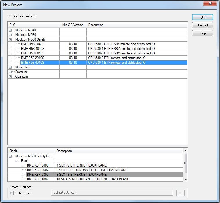
Die Funktionsparameter der Mess-Systeme werden im Reiter Safety-
Konfiguration eingestellt:
Abbildung 2: SCID-Berechnung mittels Mess-System - Parameter
Nach dem die Parameter eingestellt worden sind, kann über die Schaltfläche
Berechnen die Berechnung der SCID vorgenommen werden. Über die Schaltfläche
Download im Reiter SNCT Download werden die Parameter und SCID an das Mess-
System übertragen.
Abbildung 3: Download der SCID / Funktionsparameter
Über die Schaltfläche Upload kann die erzeugte SCID überprüft werden.
Nach einem Konfigurations-Download muss das Mess-
System neu gestartet werden.
Printed in the Federal Republic of Germany TR-Electronic GmbH 2020, All Rights Reserved
01/31/2020 TR-ECE-TI-DGB-0363 v00 Page 9 of 47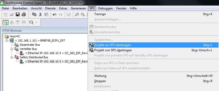
Parametrierung / CRC Berechnung
Nach dem Neustart können die im Mess-System gespeicherten Parameter überprüft
werden. Hierfür muss ein Upload im Reiter SNCT Download durchgeführt werden.
Nach dem Hochladen der Daten kann der Benutzer über die Schaltfläche Anzeigen
die hochgeladenen Daten überprüfen:
Die Werte für die SNN und SCCRC/SCTS müssen mit den Werten im Projekt Control
Expert übereinstimmen (siehe Kapitel 4).
TR-Electronic GmbH 2020, All Rights Reserved Printed in the Federal Republic of Germany
Page 10 of 47 TR-ECE-TI-DGB-0363 v00 01/31/20204 Erstellung des Beispielprojekts
Dieses Kapitel beschreibt den Ablauf zur Erstellung des Beispielprojekts unter
Verwendung der integrierten Entwicklungsumgebungs-Software (IDE) von
SCHNEIDER ELECTRIC EcoStruxure Control Expert V14.1 - 191115 und
dem optionalen M580 Safety AddOn Paket. Das Beispiel kann dazu verwendet
werden, um eine EtherNet/IP-Kommunikation mit TR Mess-Systemen aufzubauen.
Zwei Arten von Verbindungen werden dabei unterschieden:
- EtherNet/IP Verbindung (nicht sicherheitsgerichteter Positionswert)
- EtherNet/IP mit CIP Safety Verbindung (sicherheitsgerichteter Positionswert)
Zugriffsschutz
Der Zugriff auf das Projekt und Steuerung wird durch ein Passwort geschützt. Für alle
Beispiele wird das Passwort „12345678“ verwendet.
4.1 Voraussetzungen
Gefahr der Außerkraftsetzung der fehlersicheren Funktion durch
unsachgemäße Projektierung des Sicherheitsprogramms!
Die Erstellung des Sicherheitsprogramms darf nur in Verbindung mit
der von SCHNEIDER zur Software bzw. Hardware mitgelieferten
Systemdokumentation erfolgen.
Nachfolgende Beschreibungen beziehen sich auf den reinen Ablauf,
ohne dabei die Hinweise aus dem SCHNEIDER-Handbuch mit zu
berücksichtigen.
Die im SCHNEIDER-Handbuch gegebenen Informationen, Hinweise,
insbesondere die Sicherheitshinweise und Warnungen, sind daher
zwingend zu beachten und einzuhalten.
Die aufgezeigte Projektierung ist als Beispiel aufzufassen. Der
Anwender ist daher verpflichtet, die Verwendbarkeit der Projektierung
für seine Applikation zu überprüfen und anzupassen. Dazu gehören
auch die Auswahl der geeigneten sicherheitsgerichteten Hard-
warekomponenten, sowie die notwendigen Softwarevoraussetzungen.
Für das Projektbeispiel verwendete Softwarekomponenten:
● EcoStruxure Control Expert V14.1 von SCHNEIDER ELECTRIC
● M580 Safety AddOn von SCHNEIDER ELECTRIC
Für das Projektbeispiel verwendete Hardware-Komponenten:
● M580 SIL3 (BMEP58CPROS3) von SCHNEIDER ELECTRIC
● CDS582-10035 Sicherheits - Mess-System von TR-Electronic
Printed in the Federal Republic of Germany TR-Electronic GmbH 2020, All Rights Reserved
01/31/2020 TR-ECE-TI-DGB-0363 v00 Page 11 of 47Erstellung des Beispielprojekts
4.2 Hardware Konfiguration
Control Expert starten und ein neues Projekt anlegen. Nachdem die richtige
SPS ausgewählt wurde, mit OK bestätigen:
Passwort für das Projekt festlegen. Vorgabe = “12345678”.
Projekt speichern (z.B. „TR_Example_CIP_Safety.STU“)
TR-Electronic GmbH 2020, All Rights Reserved Printed in the Federal Republic of Germany
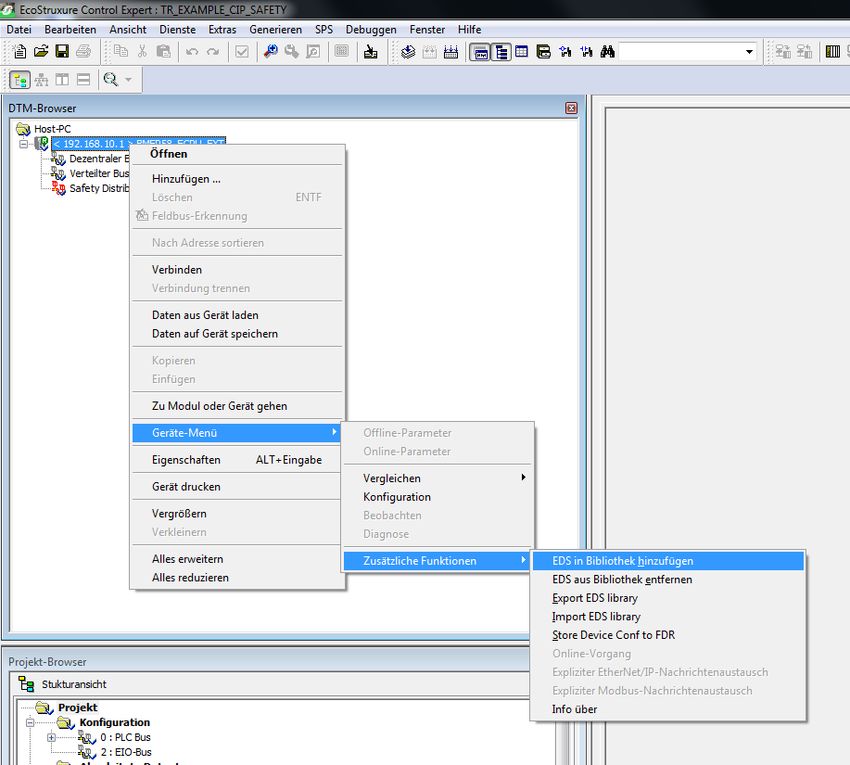
Page 12 of 47 TR-ECE-TI-DGB-0363 v00 01/31/2020 In der Menüleiste den DTM-Browser öffnen (Alt+Shift+1) und die
TR-Electronic EDS-Datei hinzufügen:
EcoStruxure Control Expert neu starten und die DTM-Bibliothek
aktualisieren
Projekt öffnen und das TR-Electronic Mess-System hinzufügen:
Printed in the Federal Republic of Germany TR-Electronic GmbH 2020, All Rights Reserved
01/31/2020 TR-ECE-TI-DGB-0363 v00 Page 13 of 47Erstellung des Beispielprojekts
CIP Safety DTM… hinzufügen
…und für den nicht sicherheitsgerichteten Positionswert (EtherNet/IP ohne CIP-
Safety), optional die EtherNet/IP DTM.
Die Eigenschaften werden nicht geändert
Eine DTM-Nachricht für die CIP-Safety-Verbindungen wird angezeigt (es sind
zwei Verbindungen notwendig). Das ist in Ordnung, dieses Problem wird später
angegangen, indem eine Sicherheitsausgangsverbindung hinzugefügt wird.
TR-Electronic GmbH 2020, All Rights Reserved Printed in the Federal Republic of Germany
Page 14 of 47 TR-ECE-TI-DGB-0363 v00 01/31/2020 Im DTM-Browser werden die hinzugefügten DTMs angezeigt:
Zuerst muss die IP-Adresse der SPS angepasst werden. Hierfür im Projekt
Browser die Eigenschaften für EIP öffnen:
Reiter IPConfig auswählen und die IP-Adresse 192.168.1.101 einstellen
Fenster schließen und Änderungen annehmen.
Printed in the Federal Republic of Germany TR-Electronic GmbH 2020, All Rights Reserved
01/31/2020 TR-ECE-TI-DGB-0363 v00 Page 15 of 47Erstellung des Beispielprojekts
Für beide DTMs müssen die IP-Adressen angepasst werden. Hierzu die
fdtSettings der Steuerung öffnen:
Beide hinzugefügte DTMs erhalten die gleiche IP-Adresse (nicht
sicherheitsgerichtete Verbindung und sicherheitsgerichtete Verbindung beziehen
sich auf das gleiche Gerät):
Die Warnung Diese Adresse ist nicht eindeutig hat in diesem Fall
keine Bedeutung, da sich beide DTMs auf das gleiche Gerät beziehen. Die DTM
sieht jetzt folgendermaßen aus:
TR-Electronic GmbH 2020, All Rights Reserved Printed in the Federal Republic of Germany
Page 16 of 47 TR-ECE-TI-DGB-0363 v00 01/31/2020 Jetzt wird der CIP-Safety-DTM eine zweite Sicherheitsverbindung hinzufügt. Die
SCHNEIDER SPS benötigt für jedes CIP Safety Gerät eine Eingangsverbindung
und eine Ausgangsverbindung. Hierfür fdtConfiguration der Safety DTM
öffnen:
In der fdtConfiguration den Schalter Verbindung hinzufügen klicken
und die Safety Output Verbindung hinzufügen. Unter General die
vorgegebene SNN und SCID einfügen:
Mit OK bestätigen.
Printed in the Federal Republic of Germany TR-Electronic GmbH 2020, All Rights Reserved
01/31/2020 TR-ECE-TI-DGB-0363 v00 Page 17 of 47Erstellung des Beispielprojekts
Um die Werte beobachten zu können, müssen Animationstabellen (normal
und safe) zum Projekt hinzugefügt werden:
Im Folgenden Neue Animationstabelle – Fenster mit OK bestätigen.
TR-Electronic GmbH 2020, All Rights Reserved Printed in the Federal Republic of Germany
Page 18 of 47 TR-ECE-TI-DGB-0363 v00 01/31/2020 In den Tabellen können nun die gewünschten Werte hinzugefügt werden. Zuerst
wird der nicht sicherheitsgerichtete Positionswert zum TabelleProcess
hinzugefügt (normaler EtherNet/IP Positionswert, nicht sicherheitsgerichtet):
Jetzt werden die sicherheitsgerichteten Werte zu TabelleSafe hinzugefügt,
nämlich TR_Safety_Position und die CTRL_IN/CTRL_OUT Werte, um die
sicherheitsgerichteten Verbindungen ein- und ausschalten zu können.
Die Tabellen sollten dann folgendermaßen aussehen:
Das Projekt kann jetzt generiert und an die SPS übertragen werden. Das Projekt
anschließend speichern.
Printed in the Federal Republic of Germany TR-Electronic GmbH 2020, All Rights Reserved
01/31/2020 TR-ECE-TI-DGB-0363 v00 Page 19 of 47Erstellung des Beispielprojekts
4.3 Projekt generieren und übertragen
Um das Projekt in die SPS laden zu können, muss das Projekt zuerst erstellt werden:
Menü Generieren auswählen und Alle Projekte generieren klicken.
Nach der Erstellung eine Verbindung zur SPS herstellen
(Menü SPS -> Verbinden)
Welche Arten von Verbindungen möglich sind, sind dem SPS-Handbuch
zu entnehmen. In diesem Beispiel wurde der USB-Anschluss verwendet.
Projekt zur SPS übertragen auswählen:
SPS-Ausführung nach Übertragung markieren und Übertragen-
Schaltfläche klicken:
Nach der Übertragung OK klicken, um das Projekt auf der SPS zu starten:
TR-Electronic GmbH 2020, All Rights Reserved Printed in the Federal Republic of Germany
Page 20 of 47 TR-ECE-TI-DGB-0363 v00 01/31/2020 Jetzt sollten die Positionswerte des Mess-Systems in den Animationstabellen zu
sehen sein – die Kommunikation (EtherNet/IP und CIP Safety) ist aktiv:
Wenn eine Sicherheitsverbindung aufgebaut wurde und
dann unterbrochen wird, d.h. die Verbindung geht verloren,
startet sie nicht automatisch wieder. Der Benutzer muss das
CTRL-Bit für die Verbindung wieder auf "1" setzen.
Printed in the Federal Republic of Germany TR-Electronic GmbH 2020, All Rights Reserved
01/31/2020 TR-ECE-TI-DGB-0363 v00 Page 21 of 47Firmware Update
5 Firmware Update
Wenn ein Update der Mess-System Firmware erforderlich ist, stellt TR-Electronic
Update-Dateien zur Verfügung, die speziell für die Mess-Systeme, die ein Update
benötigen, erstellt werden. Mit Hilfe des Tools TR SNCT Device Applet ist es
möglich, die Dateien für das Update an das Mess-System zu übertragen.
Die Kommunikation zum Mess-System erfolgt über TCP/IP,
so dass der PC, auf dem das SNCT-Tool läuft, über eine
Netzwerkkarte im gleichen IP-Adressbereich wie das Mess-
System verfügen muss (z.B. 192.168.1.100).
Auf Wunsch kann TR-Electronic den Kunden auch unterstützen, wenn ein Update
benötigt wird.
TR-Electronic GmbH 2020, All Rights Reserved Printed in the Federal Republic of Germany
Page 22 of 47 TR-ECE-TI-DGB-0363 v00 01/31/20206 Software Download, Beispiele und Bibliotheken
• EDS Datei:
www.tr-electronic.de/f/TR-ECE-ID-MUL-0067
• Software TR SNCT Device Applet für die CRC Berechnung:
www.tr-electronic.com/f/zip/TR-ECE-SW-MUL-0016
• Beispielprojekt für SCHNEIDER M580S Steuerung:
www.tr-electronic.com/f/zip/TR-ECE-SW-MUL-0015
Printed in the Federal Republic of Germany TR-Electronic GmbH 2020, All Rights Reserved
01/31/2020 TR-ECE-TI-DGB-0363 v00 Page 23 of 47Software Download, Beispiele und Bibliotheken TR-Electronic GmbH 2020, All Rights Reserved Printed in the Federal Republic of Germany Page 24 of 47 TR-ECE-TI-DGB-0363 v00 01/31/2020
Absolute Encoder CD_582_-EIP
EtherNet/IP / CIP Safety
Parameterization with Schneider
M580 SIL3 (BME P58) control system
CDV582
CDS582 / CDH582
Stock photo
_Safety Program Creation
_Configuration Example Technical
_Access to the safety-oriented data channel Information
_Parameter Definition / CRC Calculation
Printed in the Federal Republic of Germany TR-Electronic GmbH 2020, All Rights Reserved
01/31/2020 TR-ECE-TI-DGB-0363 v00 Page 25 of 47TR-Electronic GmbH
D-78647 Trossingen
Eglishalde 6
Tel.: (0049) 07425/228-0
Fax: (0049) 07425/228-33
email: info@tr-electronic.de
http://www.tr-electronic.de
Copyright protection
This Manual, including the illustrations contained therein, is subject to copyright
protection. Use of this Manual by third parties in contravention of copyright
regulations is not permitted. Reproduction, translation as well as electronic and
photographic archiving and modification require the written content of the
manufacturer. Violations shall be subject to claims for damages.
Subject to modifications
The right to make any changes in the interest of technical progress is reserved.
Document information
Release date / Rev. date: 01/31/2020
Document / Rev. no.: TR-ECE-TI-DGB-0363 v00
File name: TR-ECE-TI-DGB-0363-00.docx
Author: KUC/DIR
Font styles
Italic or bold font styles are used for the title of a document or are used for
highlighting.
Courier font displays text, which is visible on the display or screen and software
menu selections.
″< > ″ indicates keys on your computer keyboard (such as ).
Brand names
EtherNet/IP™, CIP™, CIP Safety™ and ODVA™ are trademarks of ODVA, Inc.
TR-Electronic GmbH 2020, All Rights Reserved Printed in the Federal Republic of Germany
Page 26 of 47 TR-ECE-TI-DGB-0363 v00 01/31/2020Contents
Contents .................................................................................................................. 27
1 General information ............................................................................................ 29
1.1 Applicability ............................................................................................................................. 29
2 Safety information ............................................................................................... 30
2.1 Definition of symbols and notes .............................................................................................. 30
2.2 Organizational measures ........................................................................................................ 30
2.3 Personnel qualification............................................................................................................ 30
2.4 Conditions of use for software examples ................................................................................ 31
3 Parameter definition / CRC calculation.............................................................. 32
4 Example project creation .................................................................................... 35
4.1 Prerequisites ........................................................................................................................... 35
4.2 Hardware configuration........................................................................................................... 36
4.3 Project build and Download .................................................................................................... 44
5 Firmware-Update ................................................................................................. 46
6 Download of Software, Examples and Libraries ............................................... 47
Printed in the Federal Republic of Germany TR-Electronic GmbH 2020, All Rights Reserved
01/31/2020 TR-ECE-TI-DGB-0363 v00 Page 27 of 47Contents Revision index Revision Date Index First release 01/31/2020 00 TR-Electronic GmbH 2020, All Rights Reserved Printed in the Federal Republic of Germany Page 28 of 47 TR-ECE-TI-DGB-0363 v00 01/31/2020
1 General information
This "Technical Information" includes the following topics:
● Parameter definition / CRC calculation
● Example project creation
● Access to the safety-oriented data channel
The "Technical Information" can be requested separately.
1.1 Applicability
This "Technical Information" applies exclusively for the following measuring system
series with EtherNet/IP interface and CIP Safety profile in conjunction with a
SCHNEIDER controller series M580S:
● CDV-582
● CDS-582
● CDH-582
The products are labeled with affixed nameplates and are components of a system.
The following documentation therefore also applies:
● see chapter “Other applicable documents” in the Safety Manual
www.tr-electronic.de/f/TR-ECE-BA-GB-0142
● and this optional "Technical Information"
Printed in the Federal Republic of Germany TR-Electronic GmbH 2020, All Rights Reserved
01/31/2020 TR-ECE-TI-DGB-0363 v00 Page 29 of 47Safety information
2 Safety information
2.1 Definition of symbols and notes
means that death or serious injury will occur if the required
precautions are not met.
means that death or serious injury can occur if the required
precautions are not met.
means that minor injuries can occur if the required
precautions are not met.
means that damage to property can occur if the required
precautions are not met.
indicates important information or features and application
tips for the product used.
2.2 Organizational measures
Prior to commencing work, personnel working with the measuring system must have
read and understood the Safety Manual TR-ECE-BA-GB-0142, particularly the chapter
"Basic safety instructions".
2.3 Personnel qualification
The configuration of the measuring system must be carried out by qualified personnel
only, see manual of “Control Expert” and the SNCT.
TR-Electronic GmbH 2020, All Rights Reserved Printed in the Federal Republic of Germany
Page 30 of 47 TR-ECE-TI-DGB-0363 v00 01/31/20202.4 Conditions of use for software examples
TR-Electronic GmbH cannot accept any liability or
guarantee for error-free functioning of the safety program
and application examples.
The software examples available for download serve
exclusively for demonstration purposes; they are used at
the user's own risk.
Printed in the Federal Republic of Germany TR-Electronic GmbH 2020, All Rights Reserved
01/31/2020 TR-ECE-TI-DGB-0363 v00 Page 31 of 47Parameter definition / CRC calculation
3 Parameter definition / CRC calculation
SCHNEIDER ELECTRIC’s M580 safety controller supports a type 2 safe forward
open. This means the SNN, the SCID and the functional parameters (i.e. rotational
direction) for the encoders have to be set by a standalone device tool: the SNCT
(=Safety Network Configuration Tool).
Figure 1: TR SNCT Device Applet
At first, the IP-address control has to be set to the corresponding address of the
encoder. When using the rotary switches the IP-address is in the range of
192.168.1.1 … 192.168.1.254.
The communication to the encoder is done via TCP/IP, i.e.
the PC, on which the SNCT tool is running, needs to have a
network card in the same IP-address range as the encoder
(i.e. 192.168.1.100).
With the help of the Identify-button the connection to the encoder can be checked
(LEDs are blinking).
After that the SNN is set and transferred to the encoder by means of the
Write-button.
Write access to the encoder is only possible if the encoder is
not connected to the controller and the EtherNet/IP-
communication is not running. To get write access again after
running an EtherNET/IP-connection one has to restart the
encoder.
TR-Electronic GmbH 2020, All Rights Reserved Printed in the Federal Republic of Germany
Page 32 of 47 TR-ECE-TI-DGB-0363 v00 01/31/2020The functional parameters for the encoders are set in the Safety Configuration-
tab:
Figure 2: Generating SCID with encoder parameters
After setting the parameters, the Generate-button calculates the SCID. The
parameters and the SCID can be transferred to the encoder by pushing the button
Download in the SNCT Download-tab.
Figure 3: Download of SCID and functional parameters
You can check the SCID by pressing the button Upload.
After a configuration download the encoder has to be
restarted.
Printed in the Federal Republic of Germany TR-Electronic GmbH 2020, All Rights Reserved
01/31/2020 TR-ECE-TI-DGB-0363 v00 Page 33 of 47Parameter definition / CRC calculation
After the restart you can check the parameters saved in the encoder. An Upload on
the tab SNCT Download has to be done. After uploading the data the user can click
the button Display to check the uploaded data:
The SNN and the SCCRC/SCTS have to match the values in the Control Expert
project (see chapter 4).
TR-Electronic GmbH 2020, All Rights Reserved Printed in the Federal Republic of Germany
Page 34 of 47 TR-ECE-TI-DGB-0363 v00 01/31/20204 Example project creation
This chapter describes the procedure for creating the example project using
SCHNEIDER ELECTRIC’s integrated development environment (IDE) software
EcoStruxure Control Expert V14.1 - 191115 and the optional package
M580 Safety AddOn. The example can be used to start an EtherNet/IP-
communication with the TR-encoders with two kinds of connections:
- EtherNet/IP-connection (grey position value)
- EtherNet/IP with CIP Safety connection (safe position value)
Access protection
Access to the project and to the controller is protected by a password. In every
example the password is “12345678”.
4.1 Prerequisites
Danger of deactivation of the fail-safe function through incorrect
configuration of the safety program!
The safety program must only be created in conjunction with the
system documentation provided by Schneider for the software and
hardware.
The following descriptions relate to the pure procedure and do not take
account of the instructions from the Schneider manual.
It is therefore essential to observe and comply with the information and
instructions provided in the Schneider manual, particularly the safety
instructions and warnings.
The configuration shown should be taken as an example. The user is
required to check and adapt the usability of the configuration for his
own application. This also includes the selection of suitable safety-
oriented hardware components and the necessary software
prerequisites.
Software components used for the project example:
● SCHNEIDER ELECTRIC’s EcoStruxure Control Expert V14.1
● SCHNEIDER ELECTRIC’s M580 Safety AddOn
Hardware components in the project example:
● SCHNEIDER ELECTRIC’s M580 SIL3 (BMEP58CPROS3)
● TR-Electronic’s CDS582-10035 safety encoder
Printed in the Federal Republic of Germany TR-Electronic GmbH 2020, All Rights Reserved
01/31/2020 TR-ECE-TI-DGB-0363 v00 Page 35 of 47Example project creation
4.2 Hardware configuration
Start Control Expert and create a new project. After selecting the right PLC
press OK:
Set a password for the project. We use “12345678”.
Save the project (i.e. “TR_Example_CIP_Safety.STU”)
TR-Electronic GmbH 2020, All Rights Reserved Printed in the Federal Republic of Germany
Page 36 of 47 TR-ECE-TI-DGB-0363 v00 01/31/2020 Open the DTM-Browser in the Tools-Menu Alt+Shift+1 and add the
TR-Electronic EDS:
Restart the EcoStruxure Control Expert and update the DTM-library
Open the project and add a TR-Electronic-encoder by selecting Add… :
Printed in the Federal Republic of Germany TR-Electronic GmbH 2020, All Rights Reserved
01/31/2020 TR-ECE-TI-DGB-0363 v00 Page 37 of 47Example project creation
Add CIP Safety DTM…
…and for the grey encoder value (EtherNet/IP without CIP-Safety) optional the
EtherNet/IP DTM.
We do not modify the properties in this case.
A DTM message for the CIP Safety connections is coming up (2 connections
necessary). That is OK, we handle this issue later on by adding a Safety Output
connection.
TR-Electronic GmbH 2020, All Rights Reserved Printed in the Federal Republic of Germany
Page 38 of 47 TR-ECE-TI-DGB-0363 v00 01/31/2020 The DTM-Browser shows the two added DTMs:
First we have to change the IP-address of the PLC. In the Project Browser
open the properties for EIP:
Go to the tab IPConfig and set the IP-address to 192.168.1.101
Close the window and accept the modifications.
Printed in the Federal Republic of Germany TR-Electronic GmbH 2020, All Rights Reserved
01/31/2020 TR-ECE-TI-DGB-0363 v00 Page 39 of 47Example project creation
Then we have to change the IP-address for both DTMs. To do this we have to
open the fdtSettings of the controller:
Both DTMs added get the same IP-address (the grey and safe connection go to
the same device):
The warning this address is not unique can be neglected in this case
because we have two DTMs on one physical device. The DTM looks like this:
TR-Electronic GmbH 2020, All Rights Reserved Printed in the Federal Republic of Germany
Page 40 of 47 TR-ECE-TI-DGB-0363 v00 01/31/2020 Now we have to add a second safety connection to the CIP Safety DTM. This is
because the Schneider PLC wants an input and an output connection for every
CIP Safety device. So we open the fdtConfiguration of the Safety DTM:
In the fdtConfiguration we click the button Add Connection and add the
Safety Output connection. Under General we insert our SNN and the SCID:
Click OK.
Printed in the Federal Republic of Germany TR-Electronic GmbH 2020, All Rights Reserved
01/31/2020 TR-ECE-TI-DGB-0363 v00 Page 41 of 47Example project creation
To see some values we add Animation Tables (normal and safe) to the project:
Click OK in the following “New Animation Table”-window
TR-Electronic GmbH 2020, All Rights Reserved Printed in the Federal Republic of Germany
Page 42 of 47 TR-ECE-TI-DGB-0363 v00 01/31/2020 In the tables we can add the desired values. First we add the normal (grey)
position value to the TableProcess. This is a normal EtherNet/IP-position value
which is not safe:
Than we add the safety-values to the TableSafe. We choose the
TR_Safety_Position and the CTRL_IN/CTRL_OUT values to enable or
disable the Safety-Connections.
The tables should then look like this:
We can now build the project and download it to the PLC. Do not forget to save.
Printed in the Federal Republic of Germany TR-Electronic GmbH 2020, All Rights Reserved
01/31/2020 TR-ECE-TI-DGB-0363 v00 Page 43 of 47Example project creation
4.3 Project build and Download
In order to load the project into the PLC we have to do a build of the project:
To do a build choose Build from the menu and click Rebuild All Project
After the Build we have to connect to the PLC (Menu PLC -> Connect)
Please refer to the PLC manual which kind of connections are possible. In
this example the USB-connection was used.
Then choose Transfer Project to PLC:
Mark PLC Run after Transfer and click the Transfer-button:
At the end of the transfer click OK to start the project on the PLC:
TR-Electronic GmbH 2020, All Rights Reserved Printed in the Federal Republic of Germany
Page 44 of 47 TR-ECE-TI-DGB-0363 v00 01/31/2020 After that you should see the position values of the encoder in the animation
tables – the communication (EtherNet/IP and CIP Safety) is then running:
If a safety connection is established and gets interrupted
(i.e. link lost) it does not start again automatically. The user
has to set the CTRL-Bit for the connection to “1” again.
Printed in the Federal Republic of Germany TR-Electronic GmbH 2020, All Rights Reserved
01/31/2020 TR-ECE-TI-DGB-0363 v00 Page 45 of 47Firmware-Update
5 Firmware-Update
If it is necessary to make an update of the encoder-firmware, TR-Electronic will
provide update files specific to the encoders that need an update. With the help of the
TR SNCT Device Applet it is possible to download this/these update files.
The communication to the encoder is done via TCP/IP so
the PC, on which the SNCT tool is running, needs to have a
network card in the same IP-address range as the encoder
(i.e. 192.168.1.100).
TR-Electronic will support the customer if an update is needed.
TR-Electronic GmbH 2020, All Rights Reserved Printed in the Federal Republic of Germany
Page 46 of 47 TR-ECE-TI-DGB-0363 v00 01/31/20206 Download of Software, Examples and Libraries
• EDS file:
www.tr-electronic.de/f/TR-ECE-ID-MUL-0067
• Software TR SNCT Device Applet for CRC calculation:
http://www.tr-electronic.com/f/zip/TR-ECE-SW-MUL-0016
• Example project for SCHNEIDER M580S controller:
http://www.tr-electronic.com/f/zip/TR-ECE-SW-MUL-0015
Printed in the Federal Republic of Germany TR-Electronic GmbH 2020, All Rights Reserved
01/31/2020 TR-ECE-TI-DGB-0363 v00 Page 47 of 47Sie können auch lesen