Montage- und Betriebsanleitung
←
→
Transkription von Seiteninhalten
Wenn Ihr Browser die Seite nicht korrekt rendert, bitte, lesen Sie den Inhalt der Seite unten
Montage- und Betriebsanlei-
           tung
                                       Originalbetriebsanleitung

       Mobile Schüttwand L-Form 2m

                     Dr.-Zimmer-Str. 28, 95679 Waldershof
     Telefon: 09231-9792-0 Fax: 09231-972697 E-Mail: info@a-schmelzer.de
                             www.a-schmelzer.de

Ersteller: Friedrich Schaller, Jonas Sonntag, Ergänzt: Dominik Wild
Stand: 28.07.2020 Revision: 3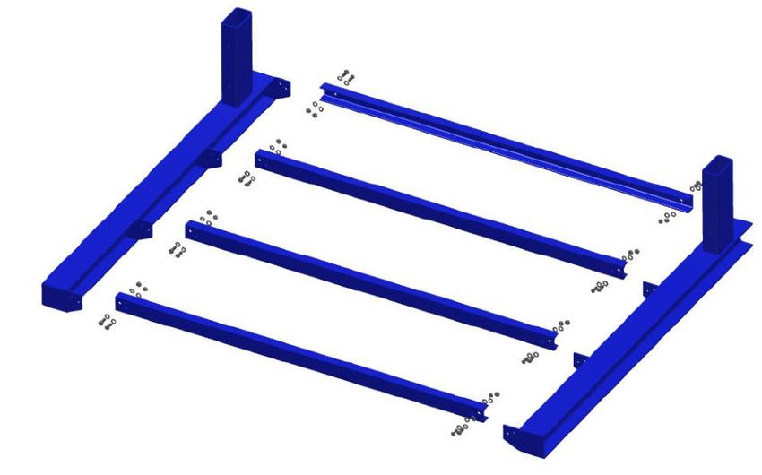
1.1.1.1

1   Vorwort........................................................................................................................... 3
          Allgemeines ............................................................................................................ 3
          Technische Vorbemerkungen.................................................................................. 4
          Bauliche Voraussetzungen ...................................................................................... 5
2   Wesentliche Baukomponenten ....................................................................................... 6
          Stückliste................................................................................................................. 6
          Wandblech - Fußblech (Pos. 1) ............................................................................... 7
          Wandblech - Mittelteil (Pos. 2) ................................................................................. 8
          Wandblech - Abschluss (Pos. 3).............................................................................. 9
          Dammwand - Wandstütze (Pos. 4/5) ....................................................................... 9
          Dammwand - Bodenblech (Pos. 6) .........................................................................10
          Dammwand - Konsole (Pos. 7/8) ............................................................................10
          Boden - Querriegel (Pos. 9)....................................................................................11
          Verschraubung (Pos. 19/20/21) ..............................................................................11
3   Montage ........................................................................................................................12
          Vorbereitung ..........................................................................................................12
          Aufbau ...................................................................................................................12
4   Betrieb der Anlage.........................................................................................................17
          Befüllung ................................................................................................................19
          Entnahme des Schüttgutes ....................................................................................20
          Sonstige Sicherheitshinweise .................................................................................21

                                                                                                                 Seite 2 von 21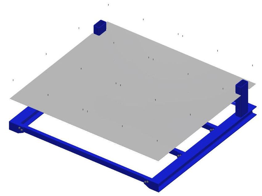
1.1.1.1

1 Vorwort

       Allgemeines

Bei der Montage und dem Betrieb der Anlage sind folgende Punkte zu beachten:

   -      Die örtlichen Bauvorschriften sind einzuhalten

   -      Vor Montagebeginn ist bauseitig zu prüfen, ob für die Errichtung der Anlage ein Bau-
          antrag zu stellen ist.

   -      Bei der Montage und dem Betrieb der Schüttwände sind die geltenden Unfallverhü-
          tungsvorschriften und Sicherheitsvorschriften zu beachten. Insbesondere sind not-
          wendige Arbeits- und Schutzgerüste zu verwenden.

   -      Auf eine ausreichende Tragfähigkeit des Untergrundes ist zu achten. Ansonsten
          müssen entsprechende Vorkehrungen getroffen werden, die auch unter Belastung
          eine ausreichende Standsicherheit der Schüttwände gewährleisten.

   -      Es ist darauf zu achten, dass die Anlage eben und lotrecht aufgestellt wird.

   -      Die geltenden Brandschutzvorschriften sind zu beachten.

   -      Der Aufbau und der Betrieb haben nach der Anleitung zu erfolgen.

   -      Die Montage- und Betriebsanleitung muss sorgfältig durchgelesen werden, um einen
          ordnungsgemäßen Aufbau und Betrieb der Anlage zu gewährleisten.

   -      Die Einzelteile sind anhand der beiliegenden Teileliste zu überprüfen, um einen voll-
          ständigen und ordnungsgemäßen Aufbau zu gewährleisten. Spätere Reklamationen
          können nicht mehr berücksichtigt werden.

   -      Die Verschraubungen und Verdübelungen müssen vollständig und kraftschlüssig un-
          ter Verwendung der beigestellten Befestigungsmittel ausgeführt werden.

   -      Die allgemeinen Sicherheitsbestimmungen für den Umgang mit den verwendeten
          Schüttgütern sind in jedem Falle zu beachten.

   -      Die Vorgaben der beiliegenden statischen Berechnung im Hinblick auf die zur Monta-
          ge notwendigen allgemeinen Bauarbeiten sind unbedingt einzuhalten.

   -      Bauseitige Veränderungen und Umbauten der Anlage sind unzulässig.

                                                                                 Seite 3 von 21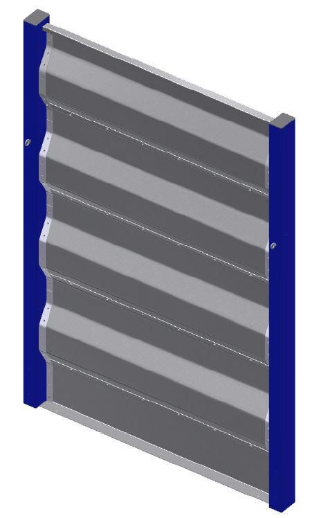
1.1.1.1

     Technische Vorbemerkungen

Diese Anleitung beschreibt den Aufbau bzw. die Montage und den Betrieb der Anlage. Sie
wird durch Zeichnungen und Schaubilder unterstützt.

Für die Montage wird ein Positionsplan einschl. Stückliste mit angegebenen Positionsnum-
mern beigefügt.

Daraus sind sowohl Art als auch Anzahl der verwendeten Bauteile ersichtlich.

In den Bildern der Montagedetails wird der Einbau der einzelnen Baukomponenten verdeut-
licht.

Alle Anker zur Befestigung von Bauteilen sind entsprechend den Herstellervorschriften zu
verwenden.

Sämtliche bauseits erforderliche Schweißarbeiten sind durch geeignetes Fachperso-
nal auszuführen.

                                                                               Seite 4 von 21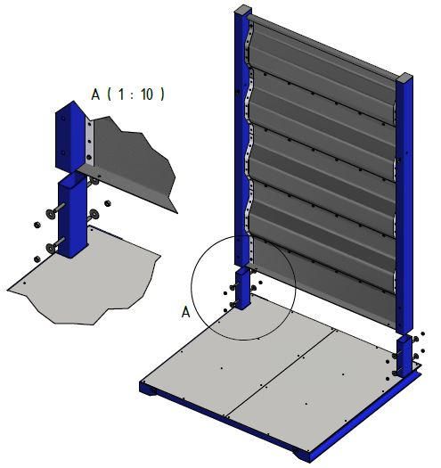
1.1.1.1

      Bauliche Voraussetzungen

Die mobilen Schüttwände sind für die Aufstellung in eine bestehende Anlage ausgelegt.

Die Bodenplatte muss ein einwandfreies senkrechtes und ebenes Aufstellen der Schüttwän-
de gewährleisten. Auch auf eine ausreichende Tragfähigkeit für die anfallende Belastung
muss geachtete werden.

Die Anlage ist für folgenden Einsatz ausgelegt:
- Aufstellort:          Innen- bzw. Trennwand in bestehende und neu errichtet Siloanla-
                        gen
                        Wind- und Schneelast müssen projektbezogen nachgewiesen
                        werden.
- Füllung:              Trockenes Getreide, Mais, oder ähnliches Schüttgut (z. B. Raps)
                 (Max. Feuchtigkeit 15%)

- Schüttgewicht:       750 kg/m³

- Reibungswinkel:       30°

Dynamische Lasten sind zu vermeiden.

Zusätzliche Ausrüstungen (z.B. Förderanlagen) sind nicht zugelassen.

Die Einbindung der Mobilen Trennwand in eine umgebende Hallenkonstruktion muss
projektbezogen geplant und gesondert statisch nachgewiesen werden.

1.4 Vorbereitende Arbeiten

Im Zuge der Aufstellung muss die Ebenheit und Tragfähigkeit der Bodenplatte bauseits
überprüft werden.

Sowohl die Gründungssohlen der Wandstützen als auch die Oberfläche der Boden-
platte müssen exakt waagrecht und eben sein, um einen sauberen Einbau der Fußble-
che zu gewährleisten.

Die Maßtoleranzen nach DIN 18201, DIN 18202 und DIN 18203 sind in jedem Fall einzu-
halten.

                                                                           Seite 5 von 21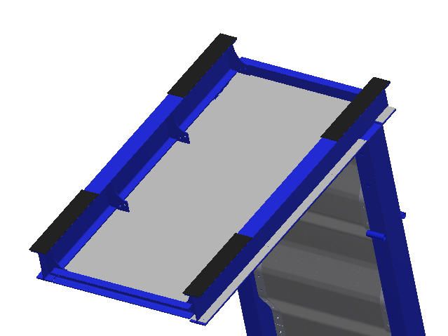
1.1.1.1

2    Wesentliche Baukomponenten
     Stückliste

                  - 4009 099 015991 L-Form 2m -

                  - 4009 099 015991 L-Form 2m -
                                                  Seite 6 von 21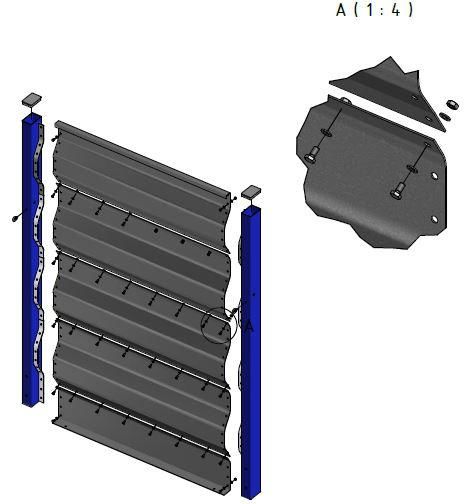
1.1.1.1

          Pos.   Stk.              Bezeichnung                Mat. / DIN
           1      1      Dammwand Wandblech Fußblech            verz.
           2      3      Dammwand Wandblech Mittelteil          verz.
           3      1      Dammwand Wandblech Abschluss           verz.
           4      1                Stütze Links                 St 37
           5      1                Stütze Rechts                St 37
           6      2                Bodenblech                   verz.
           7      1                Konsole Links                St 37
           8      1               Konsole Rechts                St 37
           9      4                 Querriegel                  St 37
          10     30     EJOT Bohrschr. JT3-FR-2H-4,8x19-E11     verz.
          11     16            6kt-Schraube M12x30             DIN 933
          12     16              6kt-Mutter M12                DIN 934
          13     32           Unterlegscheibe 13mm             DIN 125
          14     126           6kt-Schraube M10x20             DIN 933
          15     126             6kt-Mutter M10                DIN 934
          16     252           Unterlegscheibe 10,5            DIN 125
          17      2      Lamellenstopfen für Rechteckrohr        PP
          18      2                Ringschraube                DIN 580
          19      4            Gewindestange M16               DIN 975
          20     10            Unterlegscheibe d=17           DIN 9021
          21     10              6kt-Mutter M16                DIN 934

     Wandblech - Fußblech (Pos. 1)
                                                                 Seite 7 von 21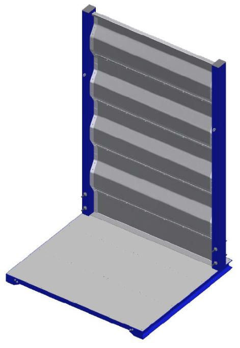
1.1.1.1

          Bild 1 Wandblech - Fußblech

          Wandblech - Mittelteil (Pos. 2)

          Bild 2 Wandblech - Mittelteil

                                            Seite 8 von 21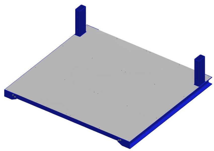
1.1.1.1

     Wandblech - Abschluss (Pos. 3)

          Bild 3 Wandblech - Abschluss

     Dammwand - Wandstütze (Pos. 4/5)

   Bild 4 Wandstütze

                                         Seite 9 von 21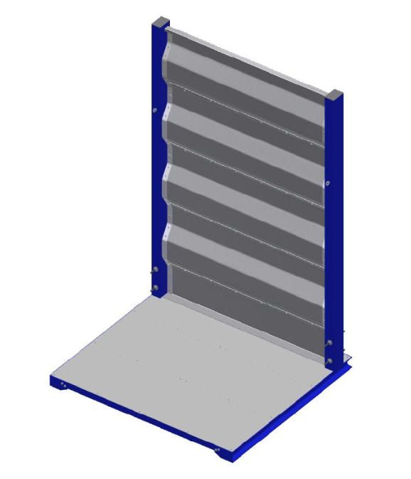
1.1.1.2

     Dammwand - Bodenblech (Pos. 6)

           Bild 5 Bodenblech

     Dammwand - Konsole (Pos. 7/8)

           Bild 6 Konsole

                                      Seite 10 von 21
1.1.1.2
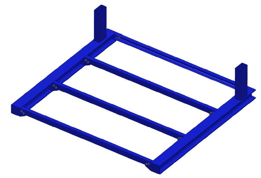
Boden - Querriegel (Pos. 9)
Bild 7 Querriegel
Verschraubung (Pos. 19/20/21)
Gewindestange M16
M16 6kt-Mutter DIN 934
Unterlegscheibe d=17 DIN 9021
Bild 8 Abspannungselement mit Verschraubung
Seite 11 von 211.1.1.2
3 Montage
Vorbereitung
Die Dammwandteile werden teilweise auf Paletten angeliefert.
Die Entladung sollte deshalb mit einem Gabelstapler erfolgen, um eine Beschädigung der Baukompo-
nenten zu vermeiden.
Es ist darauf zu achten, dass die Bauteile bei der Lagerung vor Feuchtigkeit und Verschmutzung zu
schützen sind.
Deshalb: - Bei Empfang Lieferung überprüfen
- Lagerung an einem trockenen Montageplatz
Aufbau
3.2.1 Bauteile auspacken, nach Stückliste überprüfen und nach Positionsplan bzw. Stückliste sortieren.
3.2.2 Stützen und Unterkonstruktion entsprechend Positionsplan und Stückliste montieren.
Dabei gilt es folgendes zu beachten:
- Die Dicke der Wandbleche nimmt von unten nach oben ab.
- Das nächsthöhere Blech muss das entsprechende tiefere überlappen.
- Die Wandbleche müssen an der Außenseite der Siloanlage befestigt werden, d.h. die an
den Stützen angeschweißten Zugbänder (Flachstahl) befinden sich nach der Montage auf
der Innenseite der Silowand.
- Der waagrechte Schenkel des Fußbleches weist zur Innenseite der Trennwand hin.
Seite 12 von 211.1.1.2
3.2.3 Zusammenbau Unterteil
BEACHTEN SIE: Alternativ kann bereits jetzt kann die Anti-Rutsch-Gummierung aus 3.2.7 auf der Un-
terseite aufgebracht werden.
11 (16x)
13 (32x)
12 (16x)
7 (1x)
9 (4x) 8 (1x)
Seite 13 von 211.1.1.2
3.2.4 Blechverschraubung
10 (30x)
6 (2x)
Seite 14 von 211.1.1.2
3.2.5 Zusammenbau Dammwand
17 (2x)
15 (126x)
4 (1x) 16 (252x)
3 (1x)
16 (252x)
14 (126x)
18 (2x)
5 (1x)
2 (3x)
1 (1x)
Seite 15 von 211.1.1.2
3.2.6 Zusammenbau mobile Trennwand
19 (4x)
21 (10x)
20 (10x)
20 (10x)
21 (10x)
Seite 16 von 211.1.1.2
3.2.7 Aufbringen der Anti-Rutsch-Gummierung
1. Reinigen Sie die Profile der Unterseite der mobilen Schüttwand mit Aceton
2. Bringen Sie die mitgelieferte, selbstklebende Anti-Rutsch-Gummierung auf das Profil auf.
Seite 17 von 211.1.1.2
4 Betrieb der Anlage
Voraussetzungen
Grundsätzlich ist die Schüttwand für eine Aufstellung ohne Befestigung am Hallenboden vorgesehen.
Der Aufstellort der Schüttwände muss besenrein sein. Staubige, körnige Verunreinigungen auf dem Bo-
den setzen die Reibung herab und können im schlimmsten Fall das vertuschen der Wände bewirken.
Sollten Sie über einen geglättet Betonboden verfügen, welcher bspw. mit Flügelglätter bearbeitet wurde
empfiehlt es sich die Schüttwände gegen wegrutschen zu sichern, indem hinter jeden Ständer einer
Schüttwand ein Stahlwinkel (80x80x8 Länge = 185 mm mit mittiger, einseitiger Bohrung 15mm) mittels
einer Betonschraube (z.B. Betonschraube Fischer FBS II 14 x 75 10 Bohrlochtiefe: 90mm) am Boden
befestigt wird.
Seite 18 von 211.1.1.2
Befüllung
Die Schüttwände dürfen nur bis zur Oberkante der Schüttwand befüllt werden.
Bei der Befüllung einer Silozelle ist unbedingt darauf zu achten, dass ein möglichst waagrechtes
Niveau der Schüttgutoberfläche während des Beladevorgangs eingehalten wird. Eine unter-
schiedliche Belastung gegenüber liegender Silowände ist zu vermeiden.
Nach dem Erreichen der maximal zulässigen Schütthöhe sollte die Oberfläche eben abgezogen
werden, um während der Lagerungszeit eine gleichmäßige Belüftung bzw. Trocknung des Ge-
treides zu erreichen.
Beim Befüllen mit Schaufellader, Kipper o.ä. ist zu beachten:
o Das Schüttgut darf nicht gegen die Wände geschoben werden.
o Beim Abkippen darf kein Schüttschwall gegen die Wände entstehen.
Grundsätzlich gilt bei der Befüllung:
o Jede dynamische und mechanische Belastung der Wandelemente ist untersagt.
Seite 19 von 211.1.1.2
Entnahme des Schüttgutes
Auch bei der Entleerung einer Lagerzelle ist darauf zu achten, dass immer ein symmetrischer
Lagerzustand herrscht. Die Schütthöhen von gegenüber liegenden Silowänden müssen etwa
gleich sein; max. Höhendifferenz ± 25 cm.
Eine Entnahme muss deshalb immer von der Mitte einer Silozelle her erfolgen. Dies ist beson-
ders in breiten Lagern bei der Entnahme mit mobilen Lademaschinen so bald als möglich anzu-
streben.
Beim Entnahmevorgang ist zu beachten:
o Nicht mit der Laderschaufel die Schüttwände beschädigen.
o Das Schieben des Schüttgutes gegen die Trennwand ist verboten.
o Die Wandelemente dürfen erst nach vollständiger Entleerung transportiert werden
d.h. ein Aufkippen zur Restentleerung ist verboten.
Zwischenwand (Typ T) Außenwand (Typ L)
Außenwand (Typ L)
Schüttgut
Seite 20 von 211.1.1.2
Sonstige Sicherheitshinweise
Jede über die geplante Nutzung hinaus gehende Verwendung der Anlage entspricht nicht der ge-
dachten Bestimmung. Der Betreiber haftet alleine für daraus resultierende Schäden.
Der Zutritt zu gefüllten bzw. teilweise gefüllten Lagerzellen ist verboten.
Vor jeder neuen Befüllung der Lagerzellen ist die Anlage, insbesondere der Sitz und die Festigkeit
der Verankerungen und Verschraubungen zu prüfen und ggf. sind Befestigungen wie Muttern und
Kontermuttern nachzuziehen oder zu erneuern.
Seite 21 von 21Installation- and operating
instructions
Original operating instruction
Mobile bulk wall L-shape 2m
Dr.-Zimmer-Str. 28, 95679 Waldershof
Telefon: 09231-9792-0 Fax: 09231-972697 E-Mail: info@a-schmelzer.de
www.a-schmelzer.de
creator: Friedrich Schaller, Jonas Sonntag, added: Dominik Wild translation: Daniel Purucker
Stand: 28.07.2020 Revision: 31.1.1.1
1 preamble ........................................................................................................................ 3
general .................................................................................................................... 3
preliminary technical remarks .................................................................................. 4
structural requirements............................................................................................ 5
1.4 preparatory work .......................................................................................................... 5
2 essential building components........................................................................................ 6
Parts list .................................................................................................................. 6
dam wall sheet metal - toe plate (Pos. 1)................................................................. 8
dam wall sheet metal – middle plate (Pos. 2) .......................................................... 8
dam wall sheet metal - end plate (Pos. 3)................................................................ 9
dam wall – support left (Pos. 4/5) ............................................................................ 9
dam wall – floor pan (Pos. 6) ..................................................................................10
dam wall – console (Pos. 7/8) ................................................................................10
crossbar (Pos. 9) ....................................................................................................11
screw connection (Pos. 19/20/21) ..........................................................................11
3 assembly .......................................................................................................................12
preparation .............................................................................................................12
construction ............................................................................................................12
4 operation of the system .................................................................................................18
requirements ..........................................................................................................18
filling .......................................................................................................................19
removal of the bulk material ...................................................................................20
other safety information ..........................................................................................21
Seite 2 von 211.1.1.1
1 preamble
general
The following points must be followed when installing and operating the system:
- The local building regulations must be taken into account
- Before the start of the assembly, the customer must check whether a building appli-
cation has to be submitted for the construction of the system
- When assembling and operating the bulk walls, the applicable accident prevention-
and safety regulations must be observed. In particular, necessary work and protective
scaffolding must be used
- Ensure that the subsoil has sufficient loadbearing capacity. Otherwise, appropriate
precautions must be taken to ensure adequate stability of the bulk walls even under
load
- It must be ensured that the system is set up level and perpendicular
- The applicable fire protection regulations must be taken into account
- The assembly and the operation must be carried out according to the instructions
- The installation- and operating instructions must be read carefully to ensure that the
system is set up and operated properly
- The individual parts are to be checked based on the enclosed parts list in order to en-
sure complete and correct assembly. Later complaints won´t be taken into
consideration
- The screw connections and dowels must be carried out completely and friction lock-
ing using the fasteners provided
- The general safety regulations for handling the used bulk goods must be taken into
account in any case
- The specifications of the attached static calculation with regard to the general con-
struction work required for assembly must be strictly observed
On-site changes and modifications to the system are not permitted
Seite 3 von 211.1.1.1
preliminary technical remarks
These instructions describe the construction / assembly and operation of the system. It is
supported by drawings and diagrams
A position plan including parts list with specified position numbers for assembly is attached
This shows both the type and number of components used
The installation of the individual structural components is illustrated in the pictures of the
assembly details
All anchors for fastening components are to be used in accordance with the manufacturer´s
instructions
All welding work required on site must be carried out by suitable specialist personnel
Seite 4 von 211.1.1.1
structural requirements
The mobile bulk walls are designed for installation in an existing system
The base plate hast to ensure unobjectionable vertical and level installation of the bulk walls.
Attention must also be paid to sufficient load-bearing capacity for the resulting load.
The system is designed for the following use:
- installation site: Inner- or partition wall in existing and newly built silos
Wind and snow loads must be verified on a project specific basis
- Bulk: dry grain, corn, or similar bulk material (e.g. rapeseed)
(max. humidity 15%)
- Bulk weight: 750 kg/m³
- Friction angle: 30°
Dynamic loads are to be avoided.
Additional equipment (e.g. conveyor systems) is not permitted.
The integration of the mobile partition wall into a surrounding hall construction must
be planned project-related and has to be separately verified by statics
1.4 preparatory work
During the installation, the evenness and loadbearing capacity of the floor slab must be
checked on site.
Both the foundation soles of the wall supports and the surface of the floor slab must
be exactly horizontal and level in order to ensure a clean installation of the footplate.
The dimensional tolerances according to DIN 18201, DIN 18202 and DIN 18203 must be
observed in any case.
Seite 5 von 211.1.1.1
2 essential building components
Parts list
- 4009 099 015991 L-Shape 2m -
Seite 6 von 211.1.1.1
- 4009 099 015991 L-Shape 2m -
Pos. Stk. Bezeichnung Mat. / DIN
1 1 Dam wall sheet metal toe plate galv.
2 3 Dam wall sheet metal middle plate galv.
3 1 Dam wall sheet metal end plate galv.
4 1 Support left St 37
5 1 Support right St 37
6 2 Floor pan galv.
7 1 Console left St 37
8 1 Console right St 37
9 4 Crossbar St 37
10 30 EJOT drilling screw JT3-FR-2H-4,8x19-E11 galv.
11 16 Hex screw M12x30 DIN 933
12 16 Hex nut M12 DIN 934
13 32 Washer 13mm DIN 125
14 126 Hex screw M10x20 DIN 933
15 126 Hex nut M10 DIN 934
16 252 Washer 10,5 DIN 125
17 2 Lamellar plugs for rectangular tubes PP
18 2 Eye bolt DIN 580
19 4 Threaded rod M16 DIN 975
20 10 Washer d=17 DIN 9021
21 10 Hex nut M16 DIN 934
Seite 7 von 211.1.1.1
dam wall sheet metal - toe plate (Pos. 1)
Pic 1 Dam wall sheet metal toe plate
dam wall sheet metal – middle plate (Pos. 2)
Pic 2 Dam wall sheet metal middle plate
Seite 8 von 211.1.1.1
dam wall sheet metal - end plate (Pos. 3)
Pic 3 Dam wall sheet metal end plate
dam wall – support left (Pos. 4/5)
Pic 4 Dam wall support left
Seite 9 von 211.1.1.2
dam wall – floor pan (Pos. 6)
Pic 5 floor pan
dam wall – console (Pos. 7/8)
Pic 6 console
Seite 10 von 211.1.1.2
crossbar (Pos. 9)
Pic 7 Crossbar
screw connection (Pos. 19/20/21)
Threaded rod M16
M16 hex-nut DIN 934
Washer d=17 DIN 9021
Pic 8 bracing element with screw connection
Seite 11 von 211.1.1.2
3 assembly
preparation
Some of the dam wall parts are delivered on pallets
Unloading should therefore be done with a forklift to avoid damaging the structural components.
It is important to ensure that the components are protected from moisture and contamination during
storage.
Therefore:
- Check the delivery at arrival
- Storage in a dry assembly area
construction
3.2.1 Unpack the components, check according to the parts list and sort according to the position plan
or parts list.
Assemble supports and substructure according to the parts list. Please note the following:
- The thickness of the wall plates decreases from bottom to top.
- The next higher sheet must overlap the corresponding lower one.
- The wall sheets must be attached to the outside of the silo system i.e. the tension straps
(flat steel) welded to the supports are located on the inside of the silo wall after assembly.
- The horizontal leg of the footplate points to the inside of the partition.
Seite 12 von 211.1.1.2
3.2.2 assembling the lower part
NOTE: Alternatively, the anti-slip rubber coating from 3.2.6 can be applied to the underside at this point.
11 (16x)
13 (32x)
12 (16x)
7 (1x)
9 (4x) 8 (1x)
Seite 13 von 211.1.1.2
3.2.3 sheet metal screwing
10 (30x)
6 (2x)
Seite 14 von 211.1.1.2
3.2.4 assembling dam wall
17 (2x)
15 (126x)
4 (1x) 16 (252x)
3 (1x)
16 (252x)
14 (126x)
18 (2x)
5 (1x)
2 (3x)
1 (1x)
Seite 15 von 211.1.1.2
3.2.5 Zusammenbau mobile Trennwand
19 (4x)
20 (10x)
21 (10x)
21 (10x)
20 (10x)
Seite 16 von 211.1.1.2
3.2.6 applying the anti-slip rubber coating
1. Clean the profiles on the underside of the mobile bulk wall with acetone.
2. Apply the supplied, self-adhesive anti-slip rubber coating to the profile.
Seite 17 von 211.1.1.2
4 operation of the system
requirements
In general, the bulk wall is intended for installation without being attached to the hall floor.
The installation site of the bulk walls must be swept clean. Dusty, grainy dirt on the floor reduces the
friction and in the worst case can cause the walls to slip.
If you have a smoothed concrete floor, which has been worked on with a power trowel, for example, it is
advisable to secure the bulk walls against slipping away by placing a steel bracket (80x80x8 length =
185mm with a central, one-sided hole 15mm) behind each upright of a bulk wall using a concrete screw
(e.g. concrete screw Fischer FBS II 14 x 75 10 drill hole depth: 90mm) attached to the floor.
Seite 18 von 211.1.1.2
filling
The bulk walls may only be filled up to the top edge of the bulk wall.
When filling a silo cell, it is essential to ensure that the level of the bulk material surface is as hor-
izontal as possible during the loading process. A different load on opposite silo walls is to be
avoided. After reaching the maximum permissible pouring height, the surface should be leveled
off in order to achieve even ventilation or drying of the grain during the storage time.
When filling with a shovel loader, dump truck or similar, please note:
o The bulk goods must not be pushed against the walls
o When unloading there must be no torrent against the walls
The following applies when filling:
o Any dynamic and mechanical load on the wall elements is prohibited.
Seite 19 von 211.1.1.2
removal of the bulk material
When emptying a storage cell, it must be ensured that there is always a symmetrical storage
condition. The dumping heights of opposite silo walls must be approximately the same. Max.
height difference ± 25 cm.
A removal must therefore always take place from the middle of a silo cell. This should be aimed
for as soon as possible especially in wide warehouses when removing items with mobile loading
machines.
The following must be paid attention to during the removal process:
o Do not damage the bulkheads with the loader shovel
o Pushing the bulk material against the partition is prohibited
o The elements may only be transportet after they have been completely emptied i.e.
tilting up to empty them completely is prohibited.
partition (Type T) outside wall (Type L)
outside wall (Type L)
Bulk
Seite 20 von 211.1.1.2
other safety information
Any use of the system that goes beyond the planned use does not correspond to the intended
purpose. The operator is solely liable for any resulting damage
Access to filled or partially filled storage is prohibited.
Before each new filling of the storage cells, the system, in particular the fit and the anchors and
screw connections, must be checked and, if necessary, fastening such as nuts and lock nuts must
be tightened or replaced.
Seite 21 von 21Sie können auch lesen