Naglaa El Agroudy Design of Maritime Localization System for Safe Evacuation of Cruise Ships - Beiträge aus der Elektrotechnik - Dresden 2019
←
→
Transkription von Seiteninhalten
Wenn Ihr Browser die Seite nicht korrekt rendert, bitte, lesen Sie den Inhalt der Seite unten
Beiträge aus der Elektrotechnik

              Naglaa El Agroudy

Design of Maritime Localization System for Safe
          Evacuation of Cruise Ships

                  Dresden 2019
Bibliografische Information der Deutschen Nationalbibliothek Die Deutsche Nationalbibliothek verzeichnet diese Publikation in der Deutschen Nationalbibliografie; detaillierte bibliografische Daten sind im Internet über http://dnb.dnb.de abrufbar. Bibliographic Information published by the Deutsche Nationalbibliothek The Deutsche Nationalbibliothek lists this publication in the Deutsche Nationalbibliografie; detailed bibliographic data are available on the Internet at http://dnb.dnb.de. Zugl.: Dresden, Techn. Univ., Diss., 2019 Die vorliegende Arbeit stimmt mit dem Original der Dissertation „Design of Maritime Localization System for Safe Evacuation of Cruise Ships“ von Naglaa El Agroudy überein. © Jörg Vogt Verlag 2019 Alle Rechte vorbehalten. All rights reserved. Gesetzt vom Autor ISBN 9783959470353 Jörg Vogt Verlag Niederwaldstr. 36 01277 Dresden Germany Phone: +49(0)35131403921 Telefax: +49(0)35131403918 email: info@vogtverlag.de Internet : www.vogtverlag.de
Technische Universität Dresden

      DESIGN OF MARITIME LOCALIZATION SYSTEM FOR SAFE
                EVACUATION OF CRUISE SHIPS

                          Naglaa El Agroudy

      Von der Fakultät Elektrotechnik und Informationstechnik
                an der Technischen Universität Dresden
                zur Erlangung des akademischen Grades

                           Doktoringenieur
                              (Dr.-Ing.)
                        genehmigte Dissertation

Vorsitzender:               Prof. Dr.-Ing. Dirk Plettemeier
Gutachter:                  Prof. Dr.-Ing. habil. Frank Ellinger
                            Prof. Dr.-Ing. Eckehard Steinbach
Weiteres Mitglied:          Prof. Dr.-Ing. habil. Hagen Malberg
Tag der Einreichung:        11.10.2018
Tag der Verteidigung:       11.03.2019
IV
V

Acknowledgement
   First of all, I would like to express my deep gratitude to Professor Frank Ellinger for giving
me the opportunity to work with his Chair for Circuit Design and Network Theory at
TU Dresden and for all the support and advice he provided me during my Ph.D.
   I would like to thank Professor Eckehard Steinbach, the Head of the Chair of Media
Technology at TU Munich, for being the second reviewer of this thesis work.
   I would also like to thank my group leader Dr. Niko Joram for his continuous guidance,
support and constructive feedback during the process of conducting this work. Many thanks
goes to him for the revision of this work.
   I am also indebted to my husband and former work colleague Dr. Mohammed El-Shennawy
for his unconditional support and encouragement both on the personal and professional level.
Many thanks to him for his technical support during the course of this work.
   I would like to thank Dr. Stefan Schumann for his technical lab support and for helping with
the chip bonding. I would like also to thank Paul Stärke for his chip bonding. I would also like
to thank Mrs. Katharina Isaack and Mrs. Anja Muthman for their administrative support.
   I would like to thank my colleague Manu Thayyil for his fruitful collaboration and technical
discussions during our project work Lynceus2Market. I would also like to thank
Dr. Belal Al-Qudsi for his technical support during the Lynceus2Market project. I am also
thankful to Dr. Markus Schulz who have introduced me to the Lynceus2Market project. I would
also like to take this opportunity to thank all the consortium members of the Lynceus2Market
project for the great dedication and for the successful project results that were achieved.
   I would like to thank Dr. Yehea Ismail my M.Sc. supervisor who had encouraged me to
continue and pursue my research journey. I would like to thank all my professors during my
bachelor studies, from whom I have learnt all the basics I needed to carry on this work and in
particular: Dr. Hassanein Amer, Dr. Ahmed Abou Auf, Dr. Ali Darwish, Dr. Ayman El Ezabi,
Dr. Sherif Abdel Azim. Special thanks to Dr. Iman El-Kaffas for all her support and for being
a role model to look up to. I would like to thank all my former managers and colleagues at
Mentor Graphics Egypt and in particular: Dalia El Ebiary, Nehal Saada, Wessam El-Naji, Heba
El-Atfy, Dina Soliman, Hend Samara and all my colleagues in the PVT team for the technical
experience I have learnt from them. I would also like to thank all my colleagues and friends for
their continuous encouragement and support: Mohammed H. Eissa, Hatem Ghaleb, Tamer
Abdel-Aziz, Esraa Makled, Salma Ziada, Mariam Lotfy, Noha El Kotb, Amany Abdeen, and
many more. I would also like to thank all my Egyptians friends in Germany who have always
made me feel at home and in particular: Radwa Nabil, Ahmed Samy, Sara El-Sadek, Haytham
Nabil, Nahla Medhat, Kareem Habib, Passant Atallah, Dahlia Atallah, Sara Tayel. I would also
like to thank all the TU Dresden Welcome Center team for their continuous help and support
since my relocation to Dresden.
VI

  Finally, I could not thank enough all the unconditional love and support from my family,
my parents, my siblings, my husband, my parents in-law and my son Ziad for their continuous
encouragement and support throughout my journey.
VII

Zusammenfassung
    Diese Arbeit behandelt den Entwurf von zwei Lokalisierungssystemen mit dem Ziel, ein
integriertes System für maritime Anwendungen, wie beispielsweise die sichere Evakuierung
von Kreuzfahrtschiffen zu entwickeln.
    Für Anwendungen über Bord und das Auffinden von Passagieren wird ein sehr
energiesparendes Lokalisierungssystem entwickelt. Dieses System basiert auf der Messung der
Signalstärke eines empfangenen Signals (received signal strength, RSS), welches von einer in
die Rettungsweste integrierten Elektronik empfangen wird. Das Signal wird von einer
Basisstation gesendet, welche auf einer fliegenden Drohne montiert ist. Ein neuartiger
Algorithmus, welcher eine gewichtete Version der kleinsten Fehlerquadrate (weighted least
mean square, WLMS) verwendet, wird für signalstärkebasierte Lokalisierungssysteme
entwickelt. Damit kann eine Verbesserung der Positionsgenauigkeit um 50% gegenüber der
konventionellen ungewichteten Variante (least mean squares, LMS) des Algorithmus erreicht
werden. In Simulationen wird der Einfluß des Flugmusters der Drohne auf die
Positionsgenauigkeit gezeigt. Messungen mit diesem System werden in einem Testfeld mit
einer Größe von 500 m × 350 m ausgeführt. Dort befinden sich mobile Stationen, welche mit
einem effektiven (RMS)-Fehler von 38.4 m positioniert werden können. Die Meßergebnisse
zeigen eine bessere Genauigkeit als es mit herkömmlichen Algorithmen für die
signalstärkebasierte Positionierung möglich ist. Weiterhin wurde eine großangelegte
Demonstration auf See durchgeführt, um die Funktionalität des Systems in einem realistischen
Szenario zu zeigen.
    Für das Lokalisierungssystem der Passagiere an Bord des Schiffes wird ein neuartiges,
integriertes, subharmonisches frequenzmoduliertes Dauerstrichradar (frequency modulated
continuous wave, FMCW) präsentiert, in welchem die Frequenz des gesendeten Signals von 24
GHz in einem aktiven Reflektor durch 10 geteilt wird. Ein Prototyp wird entworfen in der
GlobalFoundries (GF) 45 nm Silicon-on-Insulator-(SOI)-Technologie für die Schaltungen bei
24 GHz und in der GF 0.18 µm 7WL BiCMOS-Technologie für die Phasenregelschleife und
den Empfänger bei 2.4 GHz. Die Meßergebnisse für dieses System zeigen, daß das System, im
Gegensatz zu konventionellen FMCW-Primärradarsystemen, immun gegen starke
Mehrwegeausbreitung ist. In einer Laborumgebung erreicht das System eine
Standardabweichung für den Abstand von 3.7 mm. Bei einer Messung in einem realistischen
Innenszenario beträgt der Meßfehler für den Abstand 22.3 cm mit einer Standardabweichung
von 5.8 cm. Zusätzlich wurden in diesem Szenario auch Messungen mit dem LMS-Algorithmus
durchgeführt. Diese Messungen ergaben einen RMS-Fehler von 26.8 cm mit einer
Standardabweichung von 2.97 cm. Die Fehler liegen damit deutlich unter denen aktueller
FMCW-Lokalisierungssysteme für Anwendungen in Innenräumen. Weiterhin ist damit
experimentell bestätigt, dass das entworfene System in der Lage ist, das Problem der
Mehrwegeausbreitung von Funksignalen deutlich zu entschärfen.
VIII
IX

Abstract
    This work presents the design of two localization systems with the aim of providing an
integrated system for safe evacuation for maritime industry and cruise ships.
    In this work, a low power overboard localization system is developed that aims at providing
a system for localizing passengers in case they go overboard the ship. This system is based on
measuring the received signal strength (RSS) between smart lifejacket tags and one interrogator
station mounted inside an unmanned aerial vehicle (UAV). A new weighted least-mean-squares
(WLMS) algorithm is developed for RSS based localization. Both simulation and measurement
results are presented. It is shown that up to 50% improvement in positioning accuracy can be
achieved using the proposed WLMS algorithm compared to the conventional unweighted least-
mean-squares (LMS) solution. Simulations that study the effect of the UAV search path on the
localization accuracy are presented. Measurements are carried out in a search area of 500 m ×
350 m, where tags are localized with a root mean square (RMS) error of 38.4 m. The
measurement results show better localization accuracy compared to other RSS based
localization algorithms. In addition, large-scale sea demonstration was performed that showed
the system in an operational environment.
    For the on-board passengers’ localization system, a novel integrated sub-harmonic
frequency modulated continuous wave (FMCW) radar system based is presented, where
a 24 GHz frequency divider-by-10 is used as an active reflector tag. A practical prototype is
designed and fabricated on a GlobalFoundries (GF) 45 nm silicon-on-insulator (SOI)
technology for the 24 GHz building blocks, while a GF 0.18 µm 7WL BiCMOS technology
was used for the 2.4 GHz phase-locked-loop (PLL) and receiver (RX). Measurement results
show that as opposed to conventional primary FMCW radars, the proposed system is immune
to strong multi-path interferences resulting from the direct reflections of the interrogating
signal. When measured in lab environment, the system achieves a ranging standard deviation
of 3.7 mm. Moreover, when measured in an indoor environment, ranging results yield
a ranging RMS error of 22.3 cm with a standard deviation of 5.8 cm. In addition, indoor
positioning measurements are performed using an LMS algorithm. Measurement results show
that the sub-harmonic FMCW radar system has a positioning RMS error of 26.8 cm with
a standard deviation of 2.97 cm, which outperforms other state-of-the-art FMCW indoor
localization systems. It also further proves the system ability to mitigate multi-path
interferences in complex indoor environments.
X
XI

Table of Contents
 1 Introduction ........................................................................................................................ 1
 1.1. Motivation ...................................................................................................................... 1
 1.2. Scope, Objectives and Thesis Outline ............................................................................ 4

 2 Overboard Localization System Design ............................................................................ 7
 2.1. Introduction .................................................................................................................... 7
 2.2. System Overview ........................................................................................................... 8
 2.3. RSS-based Localization Technique ............................................................................. 12
    2.3.1.       RSS-based Ranging Method ............................................................................. 12
    2.3.2.       Positioning Algorithm ....................................................................................... 14
    2.3.3.       Simulations and Initial Measurements .............................................................. 16
 2.4. Overboard Localization System Simulations and Measurements ................................ 18
    2.4.1.       Operation and Calibration ................................................................................. 18
    2.4.2.       UAV Flight Paths Simulation Results ............................................................... 21
    2.4.3.       Measurement Results ........................................................................................ 24
    2.4.3.1.         Ground Measurement Results ....................................................................... 24
    2.4.3.2.         Overboard System Demonstration................................................................. 25
 2.5. Summary ...................................................................................................................... 28

 3 FMCW Radar System for Indoor Localization................................................................ 29
 3.1. Introduction .................................................................................................................. 29
    3.1.1.       Primary FMCW Radars ..................................................................................... 30
    3.1.2.       Secondary FMCW Radars ................................................................................. 32
    3.1.3.       Chosen FMCW Radar Architecture for the Lynceus2Market System .............. 32
 3.2. Interference Sources in Indoor Environments .............................................................. 33
    3.2.1.       Transmitter to Receiver Leakage ...................................................................... 33
    3.2.2.       Indoor Scatterers ............................................................................................... 34
    3.2.3.       Base-station to Base-station Interferences ........................................................ 35
 3.3. Proposed Sub-Harmonic FMCW Radar System .......................................................... 36
XII
3.3.1. System Overview .............................................................................................. 36
3.3.2. Sub-harmonic FMCW Radar Ranging .............................................................. 38
3.3.3. Interference Sources in the Proposed Sub-Harmonic FMCW Radar System ... 40
3.3.4. Signal to Interference Ratio (SIR) Simulations................................................. 42
3.4. Precision and Accuracy ................................................................................................ 46
3.5. Summary ...................................................................................................................... 47
4 Active Reflector Tags for Sub-Harmonic Generation ..................................................... 49
4.1. Frequency Dividers Architectures ................................................................................ 49
4.1.1. Injection Locked Frequency Dividers ............................................................... 49
4.1.2. Current-Mode Logic (CML) Frequency Divider .............................................. 52
4.1.3. Modular Programmable Dividers ...................................................................... 53
4.2. Circuit Design of a 24 GHz Frequency Divider-by-10 ................................................ 54
4.2.1. Chosen Frequency Divider Architecture ........................................................... 54
4.2.2. Input and Output Matching ............................................................................... 63
4.2.3. Electro-Static Discharge Protection .................................................................. 65
4.3. Simulations and On-wafer Measurements ................................................................... 68
4.4. PCB Design .................................................................................................................. 70
4.4.1. 24 GHz BALUN Design ................................................................................... 72
4.4.2. 24 GHz Passive Band Pass Filter Design .......................................................... 75
4.5. Active Reflector Tag PCB Measurement Results ........................................................ 76
4.6. Comparison with State-of-the-Art CMOS Frequency Dividers ................................... 77
4.7. Summary ...................................................................................................................... 79
5 FMCW Radar Front-End Design ..................................................................................... 81
5.1. Overview ...................................................................................................................... 81
5.2. Design of a 24 GHz VCO ............................................................................................ 82
5.2.1. Introduction ....................................................................................................... 82
5.2.2. Voltage Controlled Oscillator Design ............................................................... 83
5.2.3. Simulations and Measurement Results ............................................................. 96
5.2.4. Comparison with State-of-the-Art CMOS VCOs ............................................. 99
5.3. 2.4 GHz PLL and Receiver ........................................................................................ 101XIII 5.3.1. Design Overview ............................................................................................. 101 5.3.2. Simulation and Measurement Results ............................................................. 101 5.4. PCB Design for Sub-Harmonic FMCW Radar Base-Station..................................... 105 5.5. Summary .................................................................................................................... 108 6 Sub-Harmonic FMCW Radar System Measurements ................................................... 111 6.1. Lab Measurements ..................................................................................................... 111 6.2. Indoor Ranging Measurements .................................................................................. 114 6.3. Precision and Accuracy Simulations .......................................................................... 120 6.3.1. Precision Simulations ...................................................................................... 120 6.3.2. Accuracy Simulations ..................................................................................... 120 6.4. Positioning Measurement Results .............................................................................. 123 6.5. Comparison with State-of-the-Art FMCW Radars .................................................... 125 6.6. Summary .................................................................................................................... 125 7 Conclusion and Future Work ......................................................................................... 127 References ......................................................................................................................... 129 Publications....................................................................................................................... 135 List of Abbreviations ........................................................................................................ 137 List of Symbols ................................................................................................................. 141 List of Figures ................................................................................................................... 145 List of Tables .................................................................................................................... 151
Chapter 1

Introduction

    This chapter explains the motivation behind this work, gives an overview about the
localization systems to be developed and presents the thesis scope, objectives and outline.

   1.1. Motivation
     The maritime industry is currently facing critical problems associated with the evacuation
of passengers and crew-members from ships. This is particularly critical for the evacuation of
large cruise ships during emergencies. Even though there are established evacuation
procedures to be followed during maritime accidents like flooding or fire, the passengers’
behaviour becomes very unpredictable in case of such disasters, which makes it very difficult
for crew-members during evacuation.
     Despite the huge investment in the construction of new cruise ships, the cruise industry
still encounters loss of lives in the sea due to failure to adhere to evacuation procedures and
inefficient safety and evacuation plans [LYN]. Tragedies at sea, notably the 2012 Costa
Concordia and the 2014 South Korean ferry Sewol incidents, have magnified the urgent need
for improvements in the mustering and evacuation procedures, and have led to a series of new
global safety initiatives and measures. Shortly after the 2012 incident, the Cruise Lines
International Association (CLIA) and the European Cruise Council (ECC) launched a global
cruise industry operational safety review. One of the issues identified in the review was the
2 Chapter 1 Introduction
difficulty faced by both the crew and rescue bodies when trying to locate people during the
evacuation of a ship, which had added to the increased number of fatalities in that incident.
In Greek mythology, Lynceus was the son of Aphareus and Arene, and the grandson of
Perseus. He was one of the argonauts participating in the hunt of the calydonian boar. He had
supernaturally keen sight, and could even see things that were under the sea. The project
Lynceus2Market [LYN] aims to offer keen sight to our present days argonauts so that they
can ensure the safety of the passengers in emergencies irrespective of where they are located,
whether on-board the ship or overboard in the sea.
A group of companies and technology organisations involved in wireless technologies,
safety, life-saving equipment and the cruise/shipping industry formed a consortium for the
Horizon 2020 Lynceus2Market project with the aim of providing a highly integrated system
for safe-ship evacuation [LYN]. The proposed Lynceus2Market system offers the following
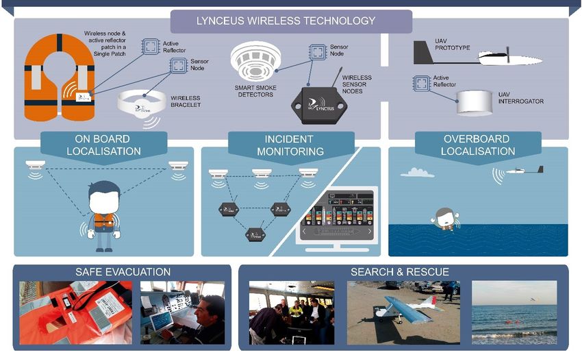
subsystems and products as shown in Figure 1-1:
Localisable lifejackets that can provide passenger location in real-time during
emergency when on-board the ship or when overboard in the sea water.
Smart smoke detectors that act as communication base-stations (BSs) and anchor
points for an on-board localisation system.
Innovative localisable bracelets able to send activity data to the emergency
management team.
Low cost fire and flooding escalation monitoring sensor networks.
Waterproofed mustering handheld devices for automatic identification and counting
of passengers during evacuation.
Smart localisable cabin key cards.
Intelligent decision support software able to fuse all localisation behavioural and
disaster escalation data to provide real-time visualisation, passenger counting and
evacuation decision support.
Innovative shore or ship-launched UAV for localising people in the sea in short time
and assisting SAR operations when accident occurs in extreme weather, during the
night or in a remote location.
Low-cost lifeboat mounted radars for people localisation in the vicinity of the boat
even in extreme weather conditions.
The project intends to deploy this system on large passenger ships provided by RCL and
Louis Cruises and verify its compliance with maritime legislations. The involved partners in
the Lynceus2Market project are namely:Chapter 1 Introduction 3
Figure 1-1 Lynceus2Market Technologies [LYN]
TALOS: this partner is specialised in project management and is the coordinator of the
project. They are leading the administrative, financial and legal management of the project.
JRCC: Search and rescue (SAR) authority that helps towards the enhancement of the
Lynceus2Market overboard localisation system to the overall SAR procedure. JRCC is
actively involved in the design of the UAV launching platform and also during the SAR
overboard localisation exercises.
Autronica and Safe Marine: Those partners are specialized in the smoke and fire detection
sector. AUTRONICA is a leading manufacturer and supplier of fire safety and maritime
safety monitoring equipment. It contributes significantly in the design and development of
both the on-board technologies as well as towards the system integration and validation via
the large-scale demonstrations. Safe Marine is involved in the on-board technologies design
and development stage as well as in the disaster escalation related tasks.
G.G. Dedalos: provides necessary know-how for the UAV related technologies that are
developed in the project. It is responsible for designing and manufacturing for the UAV and
its launching platform.
OPTIONS: is responsible for developing the decision support system. OPTIONS is also the
leader for the mustering of the handheld devices task where the counting and identification of
passengers on-board are performed.
Canepa & Campi: is responsible for the design and the production of lifejackets for
passenger ships that can carry the Lynceus2Market smart modules.4 Chapter 1 Introduction
ATEVAL and FMV: as specialised industrial associations, they are involved actively during
the demonstration and system validation stage as well as the market replication related tasks.
SignalGeneriX: is the technical manager for the project. This partner is actively involved in
the design, development and optimisation of all the hardware and software components.
CSEM: provides essential know-how for the projects low power system-on-chip technology,
low power wireless sensor network (WSN) and antennas. CSEM also contributes to the
interfacing of the wireless and wired communication media (gateway functionality of smoke
detectors) as well as to component integration, validation and testing.
TUD: The chair for circuit design and network theory is responsible for the design of the
localisation technologies that helps locating the passengers during emergencies. It also
contributes to the decision support system interface design as well as to the components
system integration and validation.
MARINEM: with its expertise on the development of shipboard emergency procedures, it
provides the knowhow on the way these procedures are applied and implemented. They are
leading the project demonstration and system validation.
RCL and LOUIS: are major cruise operators responsible for the large-scale demonstrations.
They provide their cruise ships for the demonstration and system validation of the
Lynceus2Market system under real-life operational conditions.
Lloyd's Register: is responsible of risk management, system validation, standardisation,
dissemination, market replication and exploitation.
1.2. Scope, Objectives and Thesis Outline
The scope of this work is the design of localization systems that can be easily installed
and integrated on both cruise ships and SAR vessels in order to locate simultaneously a larger
number of passengers, either on-board or overboard the ship, during emergencies. In this
work, two localization systems are developed for both overboard and on-board localization.
These systems aim at improving the response time for people localization by SAR operations
and/or ship crew-members. Moreover, the developed localization systems can be utilized in
many other applications that require localization either outdoors or indoors.
Some overboard localization solutions already exist in the market, but they either depend
on the global positioning system (GPS) for passenger localization [AIS] or on a Wi-Fi
network around the cruise ship where location data are sent in regular bursts [OET, SHS].
The use of the GPS is an expensive solution, and the use of a Wi-Fi network requires the
placement of several nodes around the cruise ship. The overboard localization system that
will be presented in this thesis aims at providing smart tags that can be easily integrated into
lifejackets and localized using either a handheld device or a UAV equipped with anChapter 1 Introduction 5
interrogator station. After the smart tags localization is performed, localization data is sent to
the command centre of the SAR operations.
As for the on-board localization, FMCW radar systems have been proven to be a good
candidate for indoor localization systems with a high precision and accuracy [SSU+12,
MOH+10]. However, the accuracy of FMCW radar systems is degraded in indoor
environments due to multi-path interferences caused by static or moving scatterers.
Therefore, this work aims at providing a novel integrated FMCW radar system based on sub-
harmonic generation that is capable of mitigating multi-paths resulting from the direct
reflections of the interrogating signal in complex indoor environments like the cruise ships
decks and cabins. The design and implementation of the sub-harmonic active reflector tags
necessary for the proposed sub-harmonic FMCW radar system is investigated as well.
This thesis is organized as follows: After presenting the motivation and the scope of the
work in this chapter, the proposed overboard RSS-based localization system is presented in
chapter 2 together with the proposed weighted least-mean-squares (WLMS) algorithm. The
design of printed circuit boards (PCB) for both smart tags and interrogator stations is
presented and both simulation and measurement results are shown and compared to the state-
of-the-art RSS-based localization systems.
In chapter 3, an introduction to FMCW radar systems is given together with the adopted
architecture suitable for the scope of the desired application. Possible interferences that affect
the accuracy of FMCW radar systems are analysed. Then, a novel FMCW radar system based
on sub-harmonic generation is proposed in order to mitigate possible multi-path interferences
in indoor environments.
In chapter 4, the circuit design of a 24 GHz frequency divider-by-10 as an active reflector
tag is presented together with the simulations and measurements results. The design and
measurements of the active reflector tag PCB are also presented.
In chapter 5, the design of a 24 GHz chirp generator is presented together with the design
of the radio frequency (RF) front-end PCB for the proposed sub-harmonic FMCW radar
system. Simulations and measurement results are presented as well.
In chapter 6, indoor ranging and positioning measurements are performed using the
proposed novel integrated sub-harmonic FMCW radar system. The results are analysed and
compared to the state-of-the-art FMCW radars.
Finally, in chapter 7, the work of this thesis is concluded and an outlook on future work is
provided.Sie können auch lesen