RWA & Lüftung steuern - Control of smoke and ventilation - SIMON PROtec Steuerungstechnik

Die Seite wird erstellt Holger Geier
 
WEITER LESEN
RWA & Lüftung steuern - Control of smoke and ventilation - SIMON PROtec Steuerungstechnik
RWA & Lüftung steuern
     Control of smoke and ventilation

       SIMON PROtec Steuerungstechnik
                    SIMON PROtec Control Panel Technology
RWA & Lüftung steuern - Control of smoke and ventilation - SIMON PROtec Steuerungstechnik
3

Inhaltsverzeichnis                                                      / Index
  4      Symbolbeschreibung
         Individuelle Fertigung
                                                                                                                          RWA Rauchabzug
                                                                                                                          Smoke Ventilation
                                                                                                                                                         6
         Simon Link
         Dokumente online                                                                                                 Natürliche Lüftung
                                                                                                                          Natural Ventilation
                                                                                                                                                        24
         Icon Description
         Customized production
         Simon Link
                                                                                                                          Auslösungen
                                                                                                                          Triggerings
                                                                                                                                                        34
         Documents online

Natürlicher Rauchabzug vom Pionier dieser Technik.                                       Natural smoke ventilation from the pioneer of this
Die Firma SIMON PROtec Systems GmbH mit Sitz in                                          technology. The company SIMON PROtec Systems
­Passau bietet seit fast 50 Jahren Antriebs- und Steue-                                  GmbH with headquarters in Passau, Germany, offers
rungstechnik für den natürlichen Rauch- und                                              actuators and control panels for natural smoke and
 ­Wärmeabzug / Rauchableitung. „Created in Bavaria“ ist                                  heat exhaust ventilation for nearly 50 years. „Created
  das Stichwort für die Entwicklung und Produktion im                                    in Bavaria“ is the slogan for the development and pro-
  eigenen Haus. SIMON PROtec liefert eine breite Palette                                 duction in-house. SIMON PROtec provides a wide ran-
  von geprüften Öffnerantrieben, sowie Kompakt- und                                      ge of approved actuators and compact/modular cont-
  Modulzentralen in die ganze Welt. Seit über 20 Jahren                                  rol panels worldwide. For more than 20 years we are
  wird zudem textiler Brandschutz in Form von automati-                                  also active in the field of textile smoke and fire curtains.
  schen Rauch- und Feuerschutzvorhängen angeboten.                                       Fire protection bulkhead, smoke area separation and
  Abschottung im Brandfall, Rauchabschnittstrennung                                      smoke and heat exhaust - SIMON PROtec stands for
  und Rauch- und Wärmeabzug – SIMON PROtec steht                                         multi-variant systems for modern fire protection. Du-
  für variantenreiche Systeme im modernen Brand-                                         ring the whole construction cycle we can assist and ad-
  schutz. Im kompletten Bauzyklus stehen wir Ihnen je-                                   vise you.
  derzeit beratend zur Seite.                                                            SIMON PROtec - we create fire safety!
  SIMON PROtec - we create fire safety!

Technische Änderungen und Irrtümer vorbehalten.   Technical modifications and errors excepted.
RWA & Lüftung steuern - Control of smoke and ventilation - SIMON PROtec Steuerungstechnik
4

    Symbolbeschreibung                                                      Symbol description
     RWA Einsatz                                  Natürliche Lüftung                             Simon Link
     Verwendung für natürlichen                   Verwendung für natürliche                      Die Steuerung hat eine
     Rauchabzug mit Gruppenanzahl                 Lüftung mit Gruppenanzahl                      Parametrierschnittstelle

     Smoke vent application                       Natural Ventilation                            Simon Link
     Made for smoke ventilation                   Made for natural ventilation                   The control panel has a
     with number of possible groups               with number of possible groups                 connection for programming.

     Motorausgang                                 Notstrom für 72 Stunden                        Geprüfte Sicherheit
     Anschluss von Antrieben mit      24          Die Zentrale enthält eine Akku-                Prüfung nach entsprechenden      prEN
                                                                                                                                 12101-9
                                      VDC
     24 V DC und / oder 230 V AC                  pufferung bis zu 72 Stunden                    Produktnormen

     Actuator output                  230         Battery backup for 72 h                        Approved safety                 DIN EN
     Connection for actuators with    VAC         The control panel includes a                   Test certificates according     12101-10

     24 V DC and/or 230 V AC                      backup battery for 72 h                        related product regulations

     Handauslöseeinrichtung                       Automatische Melder                            Potential freie Meldekontakte
     Anschlussoption für Handaus-                 Anschlussoption für automati-                  Wechslerkontakte schalten bei
     löseeinrichtungen HE-08x                     sche Melder oder BMZ                           eingestellten Zuständen

     Emergency manual switch                      Automatic triggerings                          Dry contacts for messages
     Connection for emergency                     Connection for automatic                       Changeover contacts switch
     break glass switch HE-08x                    detectors or FAS                               at set states

     Manuelle Lüftungsbedienung                   Wind- & Regenmelder                            Gebäudeleittechnik
     Anschlussoption für Druck- und               Anschlussoption mit höchster                   Anschlussoption für GLT mit
     Schlüsseltaster                              Priorität bei natürlicher Lüftung              BUS und / oder Koppler

     Manual vent switches                         Wind & Rain sensor                             Building Management
     Connection for push and key                  Connection for natural ventilati-              Connection for BMS with bus
     switch buttons                               on with highest priority                       or bus coupler

    Individuelle Fertigung                                                  Customized Production
                                                                         Steuerzentralen für RWA und natürliche Lüftung, sowie
                                                                         dazugehörige Komponenten werden nach DIN EN ISO
                                                                         9001:2015 und den entsprechenden Produktnormen produ-
                                                                         ziert und geprüft. Insbesondere M-SHEV Modulzentralen
                                                                         werden nach Kundenwunsch für die unterschiedlichsten
                                                                         Applikationen und Anforderungen individuell gefertigt.
                                                                         Anschließend erfolgt eine 100 prozentige Qualitätskontrolle
                                                                         durch vollständige Funktionsprüfung nach dem Vier-Au-
                                                                         gen-Prinzip.

                                                                         Control panels for smoke ventilation and natural ventilation
                                                                         as well as the belonging components are produced and
    Qualitätskontrolle durch SIMON PROtec Fachkräfte.                    examined according to EN ISO 9001:2015. Especially the
    Quality control by skilled employees of SIMON PROtec.                modul panels M-SHEV are manufactured individually for
                                                                         many different applications and demands as requested by
                                                                         customers. Afterwards, a quality control of 100 percent is
                                                                         carried out by examining all funtionalities in accorande with
                                                                         the 4-eyes-principle.
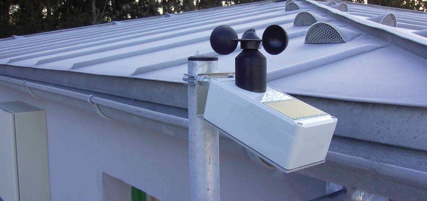
RWA & Lüftung steuern - Control of smoke and ventilation - SIMON PROtec Steuerungstechnik
5

Simon Link Software
Simon Link steht für eine umfassende                      Simon Link represents a comprehensi-
Parametrier- und Diagnose Software,                       ve parameterization and diagnosis
die es dem Anwender ermöglicht                            software, which allows the user to
SIMON PROtec Produkte zu Diagnose                         visualize SIMON PROtec products for
und Wartungszwecken zu visualisieren,                     diagnosis and maintenance, but also to
aber auch bei Bedarf spezifische Pro-                     change specific product features in
duktmerkmale zu verändern. Die                            need. The software requires therefore
Software benötigt dafür nur ein                           only a Windows®-based PC-System
Windows -basiertes PC-System mit
             ®
                                                          with an USB-interface and the SIMON
einer USB-Schnittstelle und das SIMON                     PROtec USB-300-connection
PROtec USB-300-Verbindungskabel.                          cable. With an easy-to-use graphical
Mit einer graphischen, intuitiv bedien-                   user interface (GUI) the available
baren Oberfläche werden die mögli-                        control panels are clearly visualized
chen Steuerungen übersichtlich visuali-                   and the user is guided simply through
siert und der Nutzer einfach durch die                    the application.
Anwendung geführt. Flexibel                               Applied flexible on the laptop, the
am Laptop eingesetzt können die                           needed parameters can easily be set
benötigten Parameter auch vor Ort auf                     and saved on-site, too.
der Baustelle gesetzt und gespeichert
werden.

SIMON PROtec Online
Ausführliche Produktunterlagen wie                        Detailed product documents like user
Betriebsanleitungen, Technische                           manuals, technical details and certifi-
Details und Zertifikate stehen auf                        cates are available for download on
unserer Website zum Download zur                          our website:
Verfügung:
www.simon-protec.de                                       www.simon-protec.com

Technische Änderungen und Irrtümer vorbehalten.   Technical modifications and errors excepted.
RWA & Lüftung steuern - Control of smoke and ventilation - SIMON PROtec Steuerungstechnik
6

    Rauchabzug RWA                                                                                          Seite 8 bis 23

    Die Steuerungen für den elektrischen Rauch                   Auslösestellen und aktivieren im Alarmfall
    und Wärmeabzug sind das Herzstück einer                      die Rauchabzugsöffnungen. Die integrierte
    jeden RWA-Anlage. Sie übernehmen gleich-                     Notstromversorgung bietet bis zu 72 Stun-
    zeitig die Überwachung von Bedien- und                       den Sicherheit.

    8       SHEV-3/6 (-AP)                                       12 SHEV-3-UP
    Die Kompaktzentrale mit 3 A oder 6 A Laststrom in einer      Elegantes Unterputzgehäuse mit SHEV-3, sowie integrierter
    RWA und Lüftungsgruppe für NRWG und Rauchableitung.          Handauslöseeinrichtung und zwei Lüftungstastern.

    The compact control unit with 3 A or 6 A load current in a   Elegant flush-mount housing with SHEV-3 as well as integ-
    smoke and daily vent group for smoke ventilators.            rated emergency break glass switch and two vent switches.

    14 SP-300 / 600 -AP                                          16 SHEV-2-HM
    SHEV Technologie für Sanierungen und Altbauanlagen mit       Konzipiert zur Rauchableitung in Verbindung mit Haftmag-
    3-Adern Technik für Handauslöseeinrichtungen.                neten bei einem Gesamtdauerstrom von 2 A.

    SHEV technology for redevelopment and old buildings with     Conceived for smoke ventilation in connection with mag-
    3-wires technology for emergency break glass switches.       netic clamps with a total continuous current of 2 A.
RWA & Lüftung steuern - Control of smoke and ventilation - SIMON PROtec Steuerungstechnik
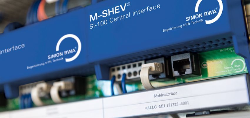
7

Smoke Ventilation                                                                                                                   Pages 8 to 23

The control units for the electric smoke and                                              station and activate the openings for smoke
heat ventilation are the heart of every smoke                                             exhaust in case of alarm. The integrated
and heat exhaust system. They take on paral-                                              battery backup offers safety up to 72 hours.
lely the monitoring of control and triggering

18 M-SHEV                                                                                 22 M-SHEV-12-AP
Digitale BUS verknüpfte Modulzentrale, individuell nach                                   Modulzentrale M-SHEV kompakt im optisch ansprechenden
Projektanforderungen geplant und produziert. Für komplexe                                 Stahlblechgehäuse mit einer RWA Gruppe und bis zu zwei
RWA Anforderungen und Lüftungskonzepte.                                                   Lüftungsgruppen.

Digital BUS combined modul control units, planned and                                     Modul control unit M-SHEV - compact in an optical attracti-
produced according to individual project requirements. For                                ve steel housing with a smoke and heat exhaust group and
complicated demands of smoke and heat exhaust and                                         up to two ventilation groups.
ventilation concepts.

Technische Änderungen und Irrtümer vorbehalten.   Technical modifications and errors excepted.
RWA & Lüftung steuern - Control of smoke and ventilation - SIMON PROtec Steuerungstechnik
8

    Kompaktzentralen           SHEV
    Compact Control Units SHEV

    —
    Die Grundlage für Entrauchung im Treppenhaus und zur Ansteuerung von
    NRWG Systemen. Höchste Sicherheit für zuverlässiges Öffnen im Brandfall
    sowie vielfältige Komfortfunktionen für die kontrollierte natürliche Lüftung.

    —

    The basis for smoke extraction in the stairwell and for controlling of smoke
    ventilators. Highest security for reliable opening in case of fire as well as
    varied comfort functions for the controlled natural ventilation.
RWA & Lüftung steuern - Control of smoke and ventilation - SIMON PROtec Steuerungstechnik
9

Technische Änderungen und Irrtümer vorbehalten.   Technical modifications and errors excepted.
RWA & Lüftung steuern - Control of smoke and ventilation - SIMON PROtec Steuerungstechnik
10

     Kompaktzentrale
     SHEV 3/6 (-AP)
     Compact Control Unit
     SHEV 3/6 (-AP)

     Typbeschreibung      Type description

     Die SHEV 3 / 6 in der Kunststoff, wie auch in der Auf-          The SHEV 3 / 6 in the plastic as well as in the steel housing
     putz-Stahlblechvariante (-AP) bilden die Basis für eine große   variant (-AP), provides the basis for a big family of compact
     Familie an Kompaktzentralen mit einer beachtlichen Anzahl       control units with a considerable number of functions.
     an Funktionen.
     Die SHEV ist in einer 3 A und einer 6 A Laststromversion        The SHEV is available in a 3 A and 6 A load current version.
     verfügbar. Unabhängig vom Gehäuse besteht die SHEV              Independant from the housing the SHEV is composed of
     aus folgenden Komponenten:                                      following components:
     • Energieversorgung (primäre Energiequelle)                     • energy supply (primary energy source)
     • Notstromversorgung (sekundäre Energiequelle)                  • emergy power supply (secundary energy source)
     • Steuerelektronik                                              • control electronics

     Vorteile /                         Advantages /
     Leistungseigenschaften             performance characteristics

     •       Geprüfte kompakte RWA Zentrale für Treppenhausentrauchung und NRWG Ansteuerung
             Examined compact smoke control units for stairwells and for smoke ventilators
     •       Mikroprozessorgestützter Aufbau - Vielfältige Funktionen für RWA und natürliche Lüftung
             Microprocessor-assisted construction - Varied functions for smoke and daily ventilation
     •       IP66 geschütztes Kunststoff- oder optisch ansprechendes Stahlblechgehäuse
             IP66 protected plastic or optical attractive steel housing
     •       Überwachte Melde- und Motorlinien, Live-Überwachung per Simon Link
             Monitored alarm- and motor lines, live-monitoring by Simon Link
     •       Flexible Kabeleinführungen von allen Seiten mit Zugentlastung
             Flexible cable entries from all sites with stress relief

     —
11
Technische Daten                                                                    Technical Data Eingänge Inputs

1                   1                                                            prEN
                                                                                12101-9
                                                                                                  DIN EN
                                                                                                  12101-10
                                                                                                                       1x HE-080 / HE-082 / HE-085
                                                                                                                       7x HE-081 / HE-086

  Eingangsspannung                           230 V AC                                Input voltage                      8x RM-3000
                                                                                                                        6x RM-2860 / TH 4860
  Leistungsaufnahme                       100 / 200 Watt                                  Input power

  Laststrom max.                                  3/6A                          max. load current

  Temperaturbereich                        -5°C - +40°C                       Temperature range
                                                                                                             Ausgänge Outputs
  Gehäuse Kunststoff                SHEV-3: 254 x 180 x 111                      Plastic Housing
  Grau, IP 66                       SHEV-6: 361 x 254 x 111                           Grey, IP 66
  (B x H x T in mm)                                                            (W x H x D in mm)                 24       3/6A                   2x 30 V / 2 A
                                                                                                                VDC
  Gehäuse Stahlblech               SHEV-3-AP: 301 x 323 x 85                       Steel Housing
  Weiß, IP 20                      SHEV-6-AP: 301 x 444 x 85                         White, IP 20
  (B x H x T in mm)                                                            (W x H x D in mm)

Funktionsübersicht           Feature Overview

RWA-Funktionen:
• Höchste Priorität im Ernstfall
• Überwachung der Meldelinien: HE, RM & BMZ
• Überwachung der Energieversorgung und Motorausgänge
• Programmierbare pot. freie Meldekontakte
• VdS Wiederantasten / Nachtaktung
• Verzögertes Ansteuern der Lastrelais
• BMZ Optionen: Anlage schließt bei Alarm & AUTO RESET möglich

Lüftungs-Funktionen:
• Frei programmierbar über DIP Schalter
• Wind- / Regenmelderanschluss
• Lüftertastereingang AUF / ZU
• Spaltlüftung per Laufzeit
• Automatische Lüftung ZU nach Zeit x
• Totmannbetrieb für sicheres Öffnen und Schließen

Smoke ventilation function list:
• Highest priority in case of fire
• Monitored lines: HE, SD & FAS
• Monitoring of power supply and motor outputs
• Programable potential free contacts for message forwarding
• VdS Re-triggering
• Delayed command for motor relays
• FAS options: windows are closing at alarm / AUTO RESET FUNCTION

Daily vent function list:
• Free programable by DIP switches
• Connection for wind / rain sensor                                                                          Grundaufbau SHEV Zentralen im Treppenhaus
• Vent switch input OPEN / CLOSE                                                                             Basic configuration of SHEV panels in stair cases
• Gap ventilation set by running time
• Automatic CLOSE after time x
• Dead-man function for safety open and close

Technische Änderungen und Irrtümer vorbehalten.    Technical modifications and errors excepted.
12

     SHEV-3-UP         Unterputz
     SHEV-3-UP flush-mounting

     —
     •   Volle Funktionalität der geprüften SHEV-3 Kompaktzentrale
         Full functionality of the examined SHEV-3 compact control panel
     •   Optisch ansprechendes Unterputzgehäuse, pulverbeschichtet in RAL 9016
         Optical attractive flush-mounting housing, powder-coated in RAL 9016
     •   Integrierte Handauslöeseinrichtung HE-08x und hochwertige Lüftertaster
         Integrated emergency switch HE-08x and high quality vent switches
13
Technische Daten                                                                   Technical Data Eingänge Inputs

1                   1                                                           prEN
                                                                               12101-9
                                                                                                 DIN EN
                                                                                                 12101-10
                                                                                                                       1x HE-080 / HE-082 / HE-085
                                                                                                                       7x HE-081 / HE-086

  Eingangsspannung                           230 V AC                               Input voltage                      8x RM-3000
                                                                                                                       6x RM-2860 / TH 4860
  Leistungsaufnahme                           100 Watt                                   Input power

  Laststrom max.                                  3A                           max. load current

  Temperaturbereich                         -5°C- +40°C                      Temperature range
                                                                                                            Ausgänge Outputs
  Gehäuse RAL 9016                    302 x 400 x 105 mm                      Housing RAL 9016
  (B x H x T)                                                                       (W x H x D)
                                                                                                                24       3A                       2x 30 V / 2 A
  Nischenmaß                           270 x 380 x 80 mm                      Niche dimensions                 VDC
  (B x H x T)                                                                       (W x H x D)

Funktionsübersicht           Feature Overview

Die SHEV-3-UP in die Unterputzvariante auf Basis der SHEV-3 Kompakt-                                        Einsatzbeispiel im Treppenhaus auf der Eingangse-
zentrale (siehe Seite 10/11) mit deren Grundfunktionen.                                                     bene zusammen mit der HE-082 Hauptbedienstelle
Die 3 A Version überzeugt in einem optisch ansprechendes Unterputzge-                                       Installation example in stair cases at the main level
häuse mit einer RAL 9016 weiß pulverbeschichteten Oberfläche. Darin                                         together with HE-082 main site switch.
sind eine Handauslöseeinrichtung HE-08x sowie zwei hochwertige
Lüftertaster für AUF/AB/STOPP integriert. Sie wird zur Rauchableitung
von Treppenhäusern nach MBO in der Eingangsebene oder an höchster
Stelle installiert.

The SHEV-3-UP in the flush-mounted version on the basis of the SHEV-3
compact control unit (see page 10/11) with its basic features.
The 3 A version convinces with an optical attractive flush-mounting
housing with a RAL 9016 white powder-coated surface. In that respect a
manual operating switch HE-08x as well as two vent switches from high
quality for up/down/stop are integrated. According to national building
regulations, it will be installed for the smoke extraction of stairwells in
the entrance level or at the highest point.

Explosionsdarstellung des SHEV-3-UP Unterputzgehäuses.
Exploded view of the SHEV-3-UP flush mounting housing.

Technische Änderungen und Irrtümer vorbehalten.   Technical modifications and errors excepted.
14

     SP-300/600           mit    3-Adern Technik
     SP-300/600 with 3-wire technology

     —
     •   Volle Funktionalität der geprüften SHEV-3 Kompaktzentrale
         Full functionality of the examined SHEV-3 compact control unit
     •   Handauslösereinrichtung HE-083 mit 3-Adern Technik
         Emergency switch HE-083 with 3-wires technology
     •   Ideal für den Sanierungseinsatz im Altbau
         Ideal for redevelopments of old buildings
15
Technische Daten                                                                    Technical Data Eingänge Inputs

1                   1                                                                             DIN EN
                                                                                                  12101-10              2x HE-083

  Eingangsspannung                           230 V AC                                Input voltage                      8x RM-3000
                                                                                                                        6x RM-2860 / TH 4860
  Leistungsaufnahme                       100 / 200 Watt                               Input power

  Laststrom max.                              3A/6A                             max. load current

  Temperaturbereich                        -5°C - +40°C                       Temperature range
                                                                                                             Ausgänge Outputs
  Gehäuse Kunststoff                 SP-300: 254 x 180 x 111                     Plastic Housing
  Grau, IP 66                        SP-600: 361 x 254 x 111                          Grey, IP 66
  (B x H x T in mm)                                                            (W x H x D in mm)                 24       3/6A                    2x 30 V / 2 A
                                                                                                                VDC
  Gehäuse Stahlblech               SP-300-AP: 301 x 323 x 85                       Steel Housing
  Weiß, IP 20                      SP-600-AP: 301 x 444 x 85                         White, IP 20
  (B x H x T in mm)                                                            (W x H x D in mm)

Funktionsübersicht           Feature Overview

Die Kompaktzentrale SP-300 / 600 basiert auf der SHEV-3 / 6 Zentralen-
technik (Seite 10/11). Speziell für dieses Produkt ist eine Zusatzplatine
installiert, welche für die Handauslöseeinrichtungen eine reduzierte
Adernzahl in der Leitungsverlegung zulässt. Mit Hilfe von nur 3-Adern
können die Signale für RWA, Reset und die Indikatoren Alarm, OK und
                                                  Störung weitergeleitet werden.

                                                  Somit eignet sich die SP-300 / 600
                                                  insbesondere für den Austausch und
                                                  Einsatz für die Sanierung in Altbauten.
                                                  Dort sind oftmals nur bauseitige
                                                  Zuleitungen mit weniger Adern vor-
                                                  handen.                                                    Die Handauslöseeinrichtung HE-083 ist eine Haupt-
                                                                                                             und Nebenbedienstelle mit RWA-Taster, sowie Reset
                                                  Die SP-300 / 600 wird in den Varianten                     und den Anzeigeelementen für Alarm, OK und
                                                  Kunststoff- und Aufputz-Blechgehäuse                       Störung. Der Anschluss erfolgt über speziell
                                                  angeboten.                                                 entwickelte 3-Adern Technik.
                                                                                                             The manual operating switch HE-083 is a main and
                                                                                                             off site switch with alarm and reset button and the
The compact control unit SP-300 / 600 is based on the SHEV 3 / 6 central                                     indicators for alarm, OK and failure. The connection
technology (page 10/11). Especially for this product an additional board is is through a special developed 3-wire technology.
installed which allows a reduced number of wires in the cable laying for
manual operating switches. By means of only 3-wires the signals for
smoke and heat exhaust, reset, the alarm indicators, OK and failure can
be transmitted.

Therefore, the SP-300 / 600 is particulary suitable for the exchange and
use in redevelopment of old buildings. In old buildings often only on-site
feed lines with just a few wires exists.

The compact control unit SP-300 / 600 are offered in a plastic or in a steel
housing.

Technische Änderungen und Irrtümer vorbehalten.    Technical modifications and errors excepted.
16

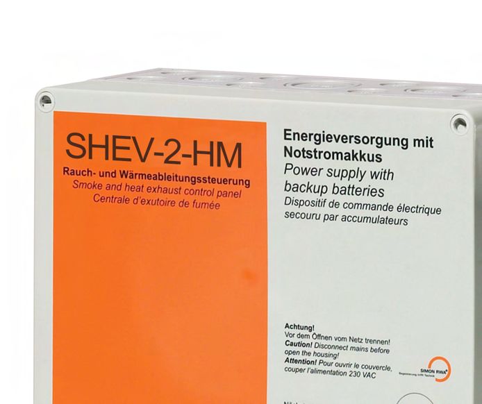
     SHEV-2-HM          für    Haftmagneten
     SHEV-2-HM for magnetic clamps

     —
     •   Optimiert für 2 Ampere Dauerlaststrom zur Ansteuerung von Haftmagneten
         Optimated for 2 ampere continous load current in order to activate magnetic clamps
     •   Notstromhaltezeit von 30 Minuten zur Überbrückung bei Netzunterbrechungen
         Emergency power dwell of 30 minutes for bridging power failures
17
Technische Daten                                                                   Technical Data Eingänge Inputs

1                   1                                                                            DIN EN
                                                                                                 12101-10
                                                                                                                          1x HE-080 / HE-082 / HE-085
                                                                                                                          7x HE-081 / HE-086

  Eingangsspannung                           230 V AC                               Input voltage                         8x RM-3000
                                                                                                                          6x RM-2860 / TH 4860
  Leistungsaufnahme                           100 Watt                                Input power

  Laststrom max.                                  2A                           max. load current

  Temperaturbereich                        -5°C - +40°C                      Temperature range
                                                                                                            Ausgänge Outputs
  Gehäuse Kunststoff                      254 x 180 x 111                       Plastic Housing
  Grau, IP 66                                                                        Grey, IP 66
  (B x H x T in mm)                                                           (W x H x D in mm)                  24          2A                          2x 30 V / 2 A
                                                                                                                VDC

Funktionsübersicht           Feature Overview

Die SHEV-2-HM basiert auf der Kompaktzentrale SHEV. Anders als beim
Kurzzeitbetrieb von RWA Antrieben benötigen Haftmagneten eine kon-
stante Ansteuerung. Die SHEV-2-HM bietet in der Ausführung für Haftma-
gneten einen dauerhaften Laststrom von 2 Ampere und kann mit unter-
schiedlichen Verriegelungsbeschlägen kombiniert werden. Wird z.B. ein
Verriegelungsbeschlag mit 0,125 A gewählt, können somit bis zu 16
Haftmagneten parallel betrieben werden.

Um Unterbrechungen im Netz auszugleichen, bietet die Steuerzentrale
eine Notstromhaltezeit von 30 Minuten. Die Umschaltzeit von Netz- auf
Notstrom ist so gering, dass die Haftmagneten durchgehend bestromt                                          Abbildung exemplarisch / Exemplary picture

werden. Die Rückstellung der zumeist mit Gasfedern kombinierten RWA
                                                                                                            Verriegelungsbeschlag mit Haftmagnet.
Fenster erfolgt manuell.                                                                                    Locking mechanism with magnetic clamp.

The product SHEV-2-HM is based on the compact control unit SHEV.
Contrary to the short term operation of smoke and heat exhaust actu-
ators, the magnetic clapms need a permanent activation. The SHEV-2-HM
offers in the version for magnetic clamps a continous load current of 2
ampereand can be combined with different locking fittings. If, for examp-
le, an interlock fitting with 0.125 A is selected, up to 16 magnetic clamps
can be operated in parallel.

In order to compensate power failures, the control unit offers an emer-
gency power dwell of 30 minutes. The changeover time from line current
to emergency power is so small that the magnetic clamps are continous-
ly energized. The retraction of the smoke and heat exhaust windows that
are mostly combined with gas springs occurs manually.

Technische Änderungen und Irrtümer vorbehalten.   Technical modifications and errors excepted.
18

     Modulzentrale            M-SHEV
     Modular Control Unit M-SHEV

     —
     Die M-SHEV ist eine digitale RWA-Steuerung. Alle logischen Verknüpfungen
     erfolgen digital anstatt analog. Das Herzstück der RWA-Steuerung ist ein
     Mikrocontroller, der alle Module per digitalem BUS miteinander verbindet.

     —

     M-SHEV is a digital control panel for smoke ventilation. All logic linking
     takes place digitally instead of analogue. The heart of the control panel is a
     microcontroller that connects all the modules together via digital BUS.
19
Technische Daten                                                                    Technical Data Eingänge Inputs

∞                   ∞                                                                             DIN EN
                                                                                                  12101-10
                                                                                                                      1x HE-080 / HE-082 / HE-085
                                                                                                                      7x HE-081 / HE-086
                                                                                                                                                    @ SI-100

  Eingangsspannung                           230 V AC                                Input voltage                    8x RM-3000
                                                                                                                                                    @ SI-100
                                                                                                                      6x RM-2860 / TH 4860
  Leistungsaufnahme                     1100 W / (24A Out)                             Input power

  Laststrom max.                          12 / 24 / 48 / 72                     max. load current
                                             + n*24 A

  IP Schutz                                       IP 54                           Protection class           Ausgänge Outputs

  Temperaturbereich                        -5°C - +40°C                       Temperature range
                                                                                                                24      12 A @ MR-120
  Gehäuseart                          Stahlblech, RAL 7035                           Housing type               VDC
                                     variable Abmessungen
                                      Steel sheet, RAL 7035                                                             4x 30 V / 1A
                                      different dimensions                                                              @ MI-100

Grundaufbau          Basic configuration

Das Schaltnetzteil (SNT) wandelt die 230 Volt der Netzversorgung in eine
stabilisierte und „saubere“ 24 Volt Versorgung. Das Zentralinterface (ZI)
ist das Steuerungszentrum der M-SHEV. Es ist das Herzstück der Zentra-
le, fungiert als eine Art Motherboard und koordiniert die Zuordnung von
RWA und Lüftungsgruppen.
Am Sensorinterface (SI) werden die Peripheriegeräte zur Auslösung RWA
angeschlossen. Dazu zählen die Handansteuereinrichtung (HE), der
Rauchmelder (RM) und die bauseits vorhandene Brandmeldeanlage
(BMZ). Pro RWA-Gruppe ist ein SI notwendig. Das Motorrelais (MR) ist
das Ausgangsmodul, welches die angeschlossenen Antriebe versorgt.
Einem SI können beliebig viele Motorrelais zugeordnet werden. Das
Abrufen aller gewünschten Informationen, z.B. „Wind-Regenmelder
aktiv“ oder „RWA ausgelöst“, erfolgt über das Meldeinterface (MI).

The switch-mode power supply (SNT) transforms the 230 V from the
mains supply into a stabilised and ‘clean’ 24 V supply. The central interfa-
ce (ZI) is the control centre of M-SHEV. It is the heart of the centre; it
functions as a kind of motherboard and coordinates the allocation of
                                                                                                             Typenbezeichnung /Type designation:
smoke and daily ventilation groups.
The peripheral devices for triggering the SHEV are connected to the                                          • M-SHEV AA/R-L(M)
sensor interface (SI). These include the emergency switch (HE), the                                          — AA Strom/Current                » 24
smoke detectors (SD) and the existing building fire alarm system (FAS).
                                                                                                             —R    RWA-Gruppen/Alarm groups    »2
One SI is required for each alarm group. The motor relay (MR) is the
output module which supplies the connected motors with power. Any                                            —L    Lüftungsgruppen/Vent groups »4
number of motor relays can be assigned to an SI. All desired informati-                                      — M MR-120 Module/MR-120 modules » 5
on, e.g. ‘wind/rain sensor active’ or ‘SHE triggered’ can be retrieved via
                                                                                                             » M-SHEV 24/2-4(5)
the message interface (MI).

Technische Änderungen und Irrtümer vorbehalten.    Technical modifications and errors excepted.
20
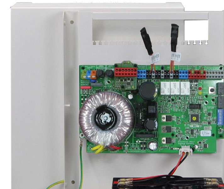
     Stromversorgung & Ladeeinrichtung                                                  Power supply & charging electronics

                                                                                                                                                   SNT-120                                         Schaltnetzteil 12 A / 24 A
                                                                                                                                                                                               wird kaskadiert in 24 A Schritten
                                                                                                                                                                                             switch-mode power supply 12 A / 24 A
                                                                                                                                                                                                    cascaded in 24 A steps

                                                                                                                                                   LI-048-12                                   Ladekarte für bis zu drei SNT-120
                                                                                                                                                   LI-048-24                                    Überwachung aller Funktionen
                                                                                                                                                   LI-048-48
                                                                                                                                                                                            Charging electronis up to three SNT-120
                                                                                                                                                                                                  Monitoring of all functions

                                                                                                                                                   Akku                                     Blei-Akkumulator für 72 h Überbrückung
                                                                                                                                                   Battery                                  Lead battery for 72 h emergency power

                                                                                                                                                   Zulassung                                           DIN EN 12101-10
                                                                                                                                                   Certifications                                        ISO 21927-9
                                                                                                                                                                                                      VdS 2344:2012-07
 B                    C                                  D                                                            E                                       F                                       VdS 2593:2002-09
                                                                                                                                                                                                          G 505006

     Zentralinterface ZI-100          Central Interface ZI-100
                                                                                                                                                                                        1

         Digitale Eingänge 1-5       Wind/Regen                     Simon Link
           Digital Inputs 1-5        Wind/Rain
                                                                                                                      Pro M-SHEV Modulzentrale ist ein                                          Per M-SHEV one central interface
                                                                                                                      Zentralinterface ZI-100 notwendig.                                        ZI-100 is necessary. It is the master
                                                                                                                      Es ist der Master in der BUS-Steue-                                       in BUS-control systems and offers
                                                                                                                      rung und bietet zentrale Anschlüsse.                                      central connections.

                                                                                                                                                                                        2
                                                                                                                      Anschlüsse:                                                               Connections:
                                                                                                                      • SIMON-LINK                                                              • SIMON-LINK
         M–SHEV®                                                                                                      • Wind- & Regenmelder                                                     • Wind & rain sensor
         ZI-100                                                                                                       • 5 frei parametrierbare Digitalein-                                      • 5 free parametrizable digital
         Zentralinterface                                                                                               gänge mit 24 V Schaltkontakt (24 V                                        inputs with 24 V switching contact
         Central Interface                                                                                              mit und ohne Batterieversorgung)                                          (with and without battery supply)

                                                                                                                      Softwareparameter:                                                3       Software parameters:
                                                                                                                      • Digitale Eingänge definieren                                             • Define digital inputs
                                                                                                                      • Prioritäten Zentrallüftung                                              • Priority central ventilation system
                                                                                                                      • Wartungszähler aktivieren                                               • Activate maintenance counter
 B      Stromversorgung
                   C    & BUS Anschluss D                                                                             E                                     F
         Power supply & BUS connection
                                 Allg. Toleranz:                Schutzvermerk
                                                                                            geprüft / geändert:        Material:                         Gewicht:      -
                                                                                         am:
                                      DIN ISO 2768 - m       ISO 16016 beachten!         von:                          Projekt:

     Sensorinterface SI-100           Sensor Interface
                                                 konstruiert:
                                          Oberfläche:
                                             am: 15.10.2014   SI-100
                                                                  gezeichnet:
                                                              am: 19.05.2017
                                                                                                                       Typ:                                           Maßstab:
                                                                                                                                                                        1:1
                                                                                                                       Bezeichnung:
                                        DIN ISO 1302     von:    mschwinge               von:   S.Kühling                                                             Revision:     1
                                                                                                                                                                                        4
                                       SIMON RWA Systeme GmbH
           RWA-Taster HE             Rauchmelder
                                      Medienstr. 8                         BMZ                                         Zeichnungsnummer:                              Blattgröße:
                                      94036 Passau                                                                                                                           A4
         Emergency switch HE          Smoke+49 851D.                       FAS SIMON RWA
                                      Tel.         98870-0
                                       Fax. +49 851 98870-70
                                                                                                                  R

                                                                                                                      Pro       RWA-Alarmgruppe ist ein
                                                                                                                       Teile-/Artikelnummer:                  Blatt:                            Per smoke vent group one sensor
                                                                               Begeisterung trifft Technik
                                                                                                                                             Modul_ZI-100_1.2  1/1
                                                                                                                      Sensorinterface SI-100 notwendig.                                         interface SI-100 is necessary. The
 B                    C                                  D                                                            E                                   F
                                                                                                                      Ihm werden die alarmauslösenden                                           SI-100 is attributed to following
                                                                                                                      Komponenten wie Handauslösetas-                                           triggering components: manual
                                                                                                                      ter HE, Rauchmelder RM und                                                operating switch HE, smoke detec-
                                                                                                                      Brandmeldezentrale BMZ zugeord-                2                          tor RM, and central fire alarm
                                                                                                                      net. Alle Eingänge sind Leitungs-                                         system BMZ. All inputs are line-mo-
                                                                                                                      überwacht.                                                                nitored.
          M–SHEV®
          SI-100
          Sensorinterface                                                                                             Anschlüsse:                                                               Connections:
          Sensor Interface
                                                                                                                      • HE (RWA-Taster)                                                         • HE (emergency break glass)
                                                                                                                      • Rauchmelder                                                             • Smoke detector
                                                                                                                      • Brandmeldezentrale                                                      • Fire Alarm System
                                                                                                                                                                                    3

                                                                                                                      Softwareparameter:                                                        Software parameters:
                                                                                                                      • RWA Gruppe zuweisen                                                     • assign smoke vent groups
        Stromversorgung & BUS Anschluss                                                                               • Prioritätenschaltung der einzelnen                                      • priority switching of the individual
         Power supply & BUS connection
                                 Allg. Toleranz:                Schutzvermerk
                                                                                           geprüft / geändert:             Eingänge HE, RM,
                                                                                                                      Material:               BMZ -
                                                                                                                                         Gewicht:                                                 inputs HE, SD, FAS
                                      DIN ISO 2768 - m     ISO 16016 beachten!
                                                                                        am:
                                                                                        von:                          • BMZ Auto-Reset
                                                                                                                      Projekt:                                                                  • FAS auto-reset
                                         Oberfläche:
                                                                konstruiert:                    gezeichnet:           • VdS Nachtaktung aktivieren
                                                                                                                      Typ:                        Maßstab:                                      • Acivate VdS retriggering
                                                         am:    15.10.2014              am:     22.05.2017
                                                                                                                      Bezeichnung:
                                                                                                                                                                      1:1
                                       DIN ISO 1302      von:   mschwinge               von:    S.Kühling                                                           Revision:
                                                                                                                                                                                    4
                                       SIMON RWA Systeme GmbH
                                       Medienstr. 8                                                                   Zeichnungsnummer:                             Blattgröße:
                                       94036 Passau                                                                                                                    A4
                                       Tel. +49 851 98870-0                               SIMON RWA
                                                                                                              R

                                                                                                                                                                    Blatt:
                                                                                                                      Teile-/Artikelnummer:
                                       Fax. +49 851 98870-70               Begeisterung trifft Technik
                                                                                                                                              Modul_SI-100_1.2       1/1
 B                    C                                  D                                                            E                                     F
B                      C                                   D                                                     E                       F
                                                                                                                                                                                                           21
    Lüftungsgruppenmodul Motorrelais MR-120                                                                     Group ventilation module Motor relay MR-120
                                                                                                                                                              1

           Motorausgang 12 A          Lüftung 1/2                      Analog
           Motor output 12 A         Ventilation 1/2
                                                                                                                 Das Motorrelais MR-120 ist das                   The motor relay MR-120 is the
                                                                                                                 Ansteuerungsmodul für 24 V DC                    control modul for 24 V DC actuators.
                                                                                                                 Antriebe. Antriebe mit einem                     Actuators with a total current up to
                                                                                                                 Gesamtstrom bis zu 12 A können in                12 A can be connected in a row per
                                                                                                                 einer Reihe pro MR-120 Modul                     MR-120 module. The powertrain is
                                                                                                                 angeschlossen werden. Der An- 2                  monitored by the DD-100 which is
                                                                                                                 triebsstrang ist leitungsüberwacht               positioned externally.
                                                                                                                 durch das extern platzierte DD-100.              A MR-120 is attributed to a ventilati-
          M–SHEV®                                                                                                Ein MR-120 wird einer Lüftungs-                  on group and at least one smoke
          MR-120                                                                                                 gruppe und mindestens einer RWA                  and heat exhaust group. It can also
          Motorrelais
          Motor Relay                                                                                            Gruppe zugewiesen. Es kann mit                   be combined with additional
                                                                                                                 weiteren MR-120 Modulen in einer                 MR-120 moduls in a large ventilati-
                                                                                                                 großen Lüftungsgruppe kombiniert                 on group.
                                                                                                                 werden.                          3

                                                                                                                 Anschlüsse:                                      Connections:
                                                                                                                 • Überwachter Motorausgang 12 A                  • Monitored motor output 12 A
        Stromversorgung & BUS Anschluss                                                                          • Zwei unabhängige Lüftertasterein-              • Two independant inputs for vent
         Power supply & BUS connection
                                 Allg. Toleranz:                  Schutzvermerk
                                                                                          geprüft / geändert:
                                                                                                                       gänge für AUF und ZU -
                                                                                                                  Material:           Gewicht:
                                                                                                                                                                    switches for OPEN & CLOSE
                                                                                       am:
                                        DIN ISO 2768 - m     ISO 16016 beachten!       von:
                                                                                                                 •Projekt:
                                                                                                                       Analogeingang 0-10 V / 4-20 mA             • Analogue inputs 0-10 V / 4-20 mA
                                                                  konstruiert:                gezeichnet:        Typ:                           Maßstab:
                                            Oberfläche:    am:    15.10.2014           am:    19.05.2017
                                                                                                                 Bezeichnung:
                                                                                                                                                 1:1
                                         DIN ISO 1302      von:   mschwinge            von:   S.Kühling                                         Revision:
                                                                                                                                                              4
         Softwareparameter:       SIMON RWA Systeme GmbH                                     Software parameters:
                                  Medienstr. 8
         • Zuordnung einer oder 94036
                                  mehrerer
                                         Passau RWA Gruppen
                                                                    Zeichnungsnummer:
                                                                                             • AssignmentBlattgröße:
                                                                                                             of one or more SHE groups
                                                                                                             A4
         • Zuordnung einer Lüftungsgruppe
                                  Tel. +49 851 98870-0
                                  Fax. +49 851 98870-70
                                                          SIMON RWA Teile-/Artikelnummer:    • AssignmentBlatt:of a ventilation group
                                                                                                            R

                                                                                          Modul_MR-120_1.2
                                                                             Begeisterung trifft Technik
                                                                                                            1/1
         • Spaltlüftung und Verzögerungszeiten                                               • Gap ventilation and delay times
B                    C                         D                    E                                 F
         • Automatisch Lüften ZU                                                             • Automatically ventilation CLOSE
         • (De-)aktivieren globaler Befehle wie Wind / Regen sowie                           • (De-)activate global commands as wind / rain as well as
           Fernsteuerung von und zu anderen MR-120 Modulen                                      remote control of and to other MR-120 moduls
B        • Totmann-Funktion
                     C        individuell pro  D Taster und RichtungE                        • Dead man´s
                                                                                                       F     function individually per switch and direction
         • Prioritätenschaltung der Eingänge                                                 • Priority switching of the inputs

    Meldeinterface MI-100              Message Interface MI-100
                                                                                                                                                              1

         Pot. freier Kontakt 1/2       Pot. freier Kontakt 3/4
            Dry contact 1/2               Dry contact 3/4
                                                                                                                 Das Meldeinterface MI-100 bietet die             The message interface MI-100 offers
                                                                                                                 Möglichkeit individuelle Zustands-               the possibilty to transmit individual
                                                                                                                 anzeigen per potentialfreien Wechs-              status indications per dry contact
                                                                                                                 ler an externe Geräte weiterzuleiten.            changeover to external devices.

                                                                                                                                                              2
                                                                                                                 Anschlüsse:                                      Connections:
                                                                                                                 • 4 pot. freie Wechsler (30 V / 1 A)             • 4 dry-contact changover (30 V/1 A)
         M–SHEV®
         MI-100                                                                                                  Softwareparameter:                               Software parameters:
         Meldeinterface                                                                                          • Zuordnung verschiedener                        • Assignment of different system
         Message Interface
                                                                                                                   Systemzustände (Abfrage                          states (query existing / not
                                                                                                                   vorhanden / nicht vorhanden) in                  existing) to AND / OR selectable
                                                                                                                   UND / ODER pro Kontakt auswähl-3                 per contact.
                                                                                                                   bar.

        Stromversorgung & BUS Anschluss
         Power supply & BUS connection
                                 Allg. Toleranz:                  Schutzvermerk
                                                                                          geprüft / geändert:    Material:           Gewicht:    -
                                                                                       am:
                                        DIN ISO 2768 - m     ISO 16016 beachten!       von:                      Projekt:

    Vorkonfiguration & Parametrierung konstruiert:
                                           Oberfläche:
                                                                                      Pre-Settings
                                                                                        gezeichnet: Typ: & Parametrization                      Maßstab:
                                                           am:    15.10.2014           am:    19.05.2017
                                                                                                                 Bezeichnung:
                                                                                                                                                  1:1
                                         DIN ISO 1302      von:   mschwinge            von:   S.Kühling                                         Revision:
                                                                                                                                                              4
                                        SIMON RWA Systeme GmbH
                                        Medienstr. 8
      SIMON PROtec Modulzentralen
                                94036 Passau          The modular control            units of SIMON
                                                                       Zeichnungsnummer:                                                        Blattgröße:
                                                                                                                                                     A4
                                Tel. +49 851 98870-0
      werden nach Kundenwunsch                        PROtec   are
                                                            SIMON  preconfi
                                                                  RWA             gured and
                                                                                                            R

                                                                       Teile-/Artikelnummer:                                                    Blatt:
                                Fax. +49 851 98870-70
                                                                                             Modul_MI-100_1.2
                                                                             Begeisterung trifft Technik
                                                                                                                                                  1/1
      vorkonfiguriert, parametiert und                 parameterised according to custo-
B                  C                         D                        E                                   F
      können ohne SimonLink Software in               mer requests. They can be commis-
      Betrieb genommen werden.                        sioned without the software Simon-
                                                      Link.
      Nachträgliche Änderungen sind
      bequem per SimonLink Software                   Subsequent changes are
      vor Ort oder durch Fernwartung                  realisable on-site in a comfortable
      durchführbar. Anlagen können 24 / 7             way with the software Simon Link or
      online überwacht werden.                        by remote control. Systems can be
                                                      online monitored 24 / 7.

    Technische Änderungen und Irrtümer vorbehalten.                 Technical modifications and errors excepted.
22

     Kompaktzentrale             M-SHEV-12-AP
     Compact Control Unit M-SHEV-12-AP

     —
     Die M-SHEV-12-AP ist eine als Kompaktzentrale ausgeführte M-SHEV Modul-
     zentrale mit 12 A Laststrom. Sie ist belegbar mit einer RWA Gruppe, sowie
     bis zu zwei Lüftungsgruppen oder mit einem Meldeinterface.
     —

     The M-SHEV-12-AP is a compact control unit based on the M-SHEV modular
     panel with 12 A load current. It can be set with one smoke ventilation group
     module and up to two vent group modules or one message interface.
23
Technische Daten                                                                    Technical Data Eingänge Inputs

1                   2                                                                             DIN EN
                                                                                                  12101-10
                                                                                                                      1x HE-080 / HE-082/ HE-085
                                                                                                                      7x HE-081/HE-086
                                                                                                                                                     @ SI-100

  Eingangsspannung                           230 V AC                                Input voltage                     8x RM-3000
                                                                                                                                                     @ SI-100
                                                                                                                       6x RM-2860 / TH 4860
  Leistungsaufnahme                               420 W                                Input power

  Laststrom max.                                  12 A                          max. load current

  Freie Modul-                                      3                                 Free Module
  einheiten (FME)                                                                    Entities (FME)          Ausgänge Outputs

  IP Schutz                                       IP 20                           Protection class
                                                                                                                24       12 A @ MR-120
  Temperaturbereich                        -5°C - +40°C                       Temperature range                VDC

  Gehäuse Stahlblech                     400 x 516 x 155                           Steel Housing                         4x 30 V / 1A
  Weiß                                                                                      White                        @ MI-100
  (B x H x T in mm)                                                            (W x H x D in mm)

Grundaufbau          Basic configuration

Das Schaltnetzteil (SNT) wandelt die 230 Volt der Netzversorgung in eine stabili-                                    Die M-SHEV-12-AP als Kompaktzentrale
sierte und „saubere“ 24 Volt Versorgung. Das Zentralinterface (ZI) ist das Steue-                                    basierend auf einem modularen Sys-
rungszentrum der M-SHEV. Es ist das Herzstück der Zentrale, fungiert als eine Art                                    tem bietet drei freie Moduleinheiten
Motherboard und koordiniert die Zuordnung von RWA-Gruppen und Lüftung.                                               (FME) zur Bestückung mit M-SHEV
Am Sensorinterface (SI) werden die Peripheriegeräte zur Auslösung RWA ange-                                          Modulen. In der Standardausführung
schlossen. Dazu zählen die Handansteuereinrichtung (HE), der Rauchmelder (RM)                                        hat sie ein Sensoreinterface SI-100 und
und die bauseits vorhandene Brandmeldeanlage (BMZ). Pro RWA-Gruppe ist ein                                           ein Motorrelais MR-120 zur Ansteue-
SI nötig. Das Motorrelais (MR) ist das Ausgangsmodul, das die angeschlossenen                                        rung einer RWA und Lüftungsgruppe.
Antriebe versorgt. Einem SI können beliebig viele Motorrelais zugeordnet wer-                                        Der dritte freie Platz kann für eine
den. Das Abrufen aller gewünschten Informationen, z.B. „Wind-Regenmelder                                             weitere Lüftungsgruppe oder einem
aktiv“ oder „RWA ausgelöst“, erfolgt über das Meldeinterface (MI).                                                   Meldeinterface verwendet werden.

The switch-mode power supply (SNT) transforms the 230 V from the mains                                               The M-SHEV-12-AP as compact control
supply into a stabilised and ‘clean’ 24 V supply. The central interface (ZI) is the                                  unit is based on a modular system and
control centre of M-SHEV. It is the heart of the centre; it functions as a kind of                                   offers three free modular entities (FME)
motherboard and coordinates the allocation of smoke and daily ventilation                                            for usage with M-SHEV modules. The
groups.                                                                                                              standard version includes one sensor
The peripheral devices for triggering the SHEV are connected to the sensor                                           interface SI-100 and one motor relay
interface (SI). These include the emergency switch (HE), the smoke detectors (SD) MR-120 for the control of one smoke
and the existing building fire alarm system (FAS). One SI is required for each                                       vent and one daily vent group. The
alarm group. The motor relay (MR) is the output module which supplys the                                             third free space can be used for ano-
motors with power. Any number of motor relays can be assigned to an SI. All                                          ther daily vent group or for a message
desired information, e.g. ‘wind/rain sensor active’ or ‘SHE triggered’ can be                                        interface.
retrieved via the message interface (MI).

Technische Änderungen und Irrtümer vorbehalten.    Technical modifications and errors excepted.
24

     Natürliche Lüftung                                                                                       Seite 26 bis 33

     Mit Kontrollierter Natürlicher Lüftung (KNL)                     Energiekosten entsprechend gesenkt. Auto-
     steigt die Luftqualität und der Komfort in                       matisierte Fenster und Klappen werden
     Gebäuden nachweislich an. Dazu werden die                        bedarfsorientiert geöffnet und geschlossen.

     23 VENT-3/6                                                      28 M-VENT
     Die Kompaktzentrale mit 3 A oder 6 A Laststrom mit einer         Digitale BUS verknüpfte Modulzentrale, individuell nach
     Lüftungsgruppe im Aufputzgehäuse für 24 V DC Antriebe.           Projektanforderungen geplant und produziert. Geeignet für
     Sie besitzt verschiedene Komfortlüftungsfunktionen und           komplexe Lüftungskonzepte in Verbindung mit der Gebäu-
     Anschlüsse für manuelle Bedienelemente sowie Wind- und           deleittechnik. Die Lüftungsgruppenmodule können in
     Regenmelder. Das optisch ansprechende Aufputzgehäuse             Einzel- oder Großgruppen kombiniert werden.
     enthält eine zusätzliche Folientastatur mit Lüftungstastern.

     The compact control unit with 3 A or 6 A load current in one     A modular control unit digital combined with BUS, planned
     ventilation group for 24 V DC actuators. It disposes different   and produced individually according to project require-
     features for comfort ventilation and connections for manual      ments. Appropriate for clompexe ventilation concepts in
     operating elements as well as wind- and rain detectors. The      connection with the building control system. The modules
     good-looking wall-mounted housing includes an additional         for the ventilation groups can be combined in individual or
     membrane keypad with vent switches.                              large groups.
25

Natural Ventilation                                                                                                                Pages 26 to 33

With controlled natural ventilation (CNV) the                                             energy costs are reduced accordingly. Auto-
air quality and the comfort inside a building                                             mated windows and flaps are openened and
increases demonstrably. In addition the                                                   closed needs-oriented.

30 VENT-61-AP                                                                             32 AP-N 3/6
Die Lüftungszentrale für Zuhause. Die VENT-61-AP steuert                                  Die Lüftungssteuerung AP-N 3/6 ist ideal für das Öffnen und
230 V AC Antriebe in einer Gruppe oder lässt sich mit weite-                              Schließen von 24 V DC Antrieben bei klassischer Ansteue-
ren Zentralen kombinieren. Sie besitzt verschiedene Kom-                                  rung 230 V AC (LAUF / LZU).
fortlüftungsfunktionen und mehrere Eingänge.

The ventilation control unit for use at home. The VENT-61-AP                              The ventilation control panel AP-N 3/6 is ideal for open and
controls 230 V AC actuators in a group or can be combined                                 close of 24 V DC actuators by conventional activation 230 V
with additional control units into larger groups. It offers                               AC (LOPEN / LCLOSE).
diferent features for comfort ventilation and disposes
several inputs.

Technische Änderungen und Irrtümer vorbehalten.   Technical modifications and errors excepted.
26

     Lüftungszentrale                VENT-3  / 6 -AP
     Ventilation control unit VENT-3 / 6 -AP

     —
     •   Ansteuerung zur kontrollierten natürlichen Lüftung von 24 V DC Antrieben
         Activation for controlled natural ventilation of 24 V DC actuators
     •   Optisch ansprechendes Aufputzgehäuse, pulverbeschichtet in RAL 9016 mit
         integrierter Folientastatur für AUF und ZU Befehl.
         Good-looking steel-housing, powder-coated in RAL 9016 with integrated
         foil-switch for OPEN and CLOSE command.
     •   Einstellung verschiedener Komfortlüftungsfunktionen, z.B. Spaltlüftung und
         automatisches Schließen nach frei einstellbarer Zeit.
         Setting of various comfort ventilation functions, e. g. gap ventilation and
         automatical closing according to freely adjustable time.
27
Technische Daten                                                                    Technical Data Eingänge Inputs

                    1
  Eingangsspannung                           230 V AC                                Input voltage   Ausgänge Outputs

  Leistungsaufnahme                       100 / 200 Watt                               Input power
                                                                                                         24        3/6A                  1x 30 V / 2 A
  Laststrom max.                                  3/6A                          max. load current       VDC

  Temperaturbereich                        -5°C - +40°C                       Temperature range

  Gehäuse Stahlblech               VENT-3-AP: 301 x 323 x 85                       Steel Housing
  Weiß, IP 20                      VENT-6-AP: 301 x 444 x 85                         White, IP 20
  (B x H x T in mm)                                                            (W x H x D in mm)

Funktionsübersicht           Feature Overview

Die richtige Belüftung von Gebäuden und Räumen gewinnt immer mehr                                    Lüftungs-Funktionen:
an Bedeutung. Denn ein ökonomischer und abgestimmter Luftaustausch                                   • Frei programmierbar über DIP Schalter
sorgt für gleichbleibendes Wohlbefinden und eine hohe Energieeffzienz.                               • Wind- / Regenmelderanschluss
Mit der neuen VENT 3/6 Steuerzentrale von SIMON PROtec können sie                                    • Lüftertastereingang AUF / ZU
die Belüftng ihrer Gebäude ideal anpassen.                                                           • Spaltlüftung per Laufzeit
                                                                                                     • Automatische Lüftung ZU nach Zeit x
Die kompakte VENT 3/6 bietet ihnen sämtliche Möglichkeiten. Sie können                               • Totmannbetrieb für sicheres Öffnen und
die Zentrale ohne Zubehör nur über die integrierte Folientastatur betrei-                              Schließen
ben, oder sie erweitern Ihre Steuerung mit Regensensor, Windmelder
oder weiteren Lüftungstastern und Thermostaten. Den Grad der automa-                                 Ventilation functions:
tisierung können sie dabei jederzeit selbst bestimmen.                                               • Free programable by DIP switches
                                                                                                     • Wind & Rain sensor connection
The appropriate ventilation of buildings is gaining more and more                                    • Daily vent input OPEN / CLOSE
attention. This is because an economic and coordinated air exchange                                  • Gap ventilation by running time
enables consistent wellbeing and a high energy e iciency. With the new                               • Automatic CLOSE after time x
control unit VENT 3/6 from SIMON PROtec you can customize the venti-                                 • Dead-man function for safety OPEN / CLOSE
lation of your buildings perfectly to your needs.

The compact VENT 3/6 provides you all possibilities. You can run the
control unit without any additional periphery by only using the integra-
ted membrane control interface. Or you expand your system by adding
various features like rain and wind sensors, additional switches or
thermostats. You can choose the level of automentation by yourself.

Die VENT Lüftungszentralen werden mit einer Folientastatur mit zwei Lüftertastern
auf der Frontseite ausgestattet.
The VENT ventilation panels are equipped with a foil switch with two ventilation
buttons on the front cover.

Technische Änderungen und Irrtümer vorbehalten.    Technical modifications and errors excepted.
28

     Lüftungsmodulzentrale                   M-VENT
     Modular Ventilation Control Unit M-VENT

     —
     Die Lüftungsmodulzentrale M-VENT basiert auf der M-SHEV Zentrale mit
     BUS verknüpften Modulen zur Ansteuerung von 24 V DC und 230 V AC
     Antrieben in der kontrollierten natürlichen Lüftung.

     —

     The modular ventilation control unit M-VENT is based on the M-SHEV
     central unit with bus connected modules. It commands actuators with
     24 V DC and 230 V AC for controlled natural ventilation.
29
Technische Daten                                                                    Technical Data Eingänge Inputs

                    ∞
  Eingangsspannung                           230 V AC                                Input voltage   Ausgänge Outputs

  Laststrom max.                             5 / 10 / 20                        max. load current
                                                                                                         24       12 A @ MR-120
  IP Schutz                                       IP 20                           Protection class      VDC

  Temperaturbereich                        -5°C - +40°C                       Temperature range                   4x 30 V / 1A
                                                                                                                  @ MI-100
  Gehäuse Stahlblech                SMALL: 301 x 323 x 85                          Steel Housing
  Weiß                              MIDDLE: 301 x 444 x 85                                  White
  (B x H x T in mm)                 LARGE: 406 x 444 x 170                     (W x H x D in mm)

Grundaufbau          Basic configuration

Die M-VENT ist die digitale Lüftungszentrale basierend auf der M-SHEV                                Typenbezeichnung /Type designation:
Technologie. Über das Schaltnetzteil werden die 24 V DC für die Module                               • M-VENT AA/L(M)
und Antriebe erzeugt. Das Motorrelais (MR) ist das Ausgangsmodul,
                                                                                                     — AA Strom/Current                » 24
welches die angeschlossenen Antriebe versorgt. Die Motorrelais können
autark in einer eigenen Gruppe oder im Verbund mit mehreren Modulen                                  —L    Lüftungsgruppen/Vent groups »4
in einer großen Gruppe kombiniert werden. Die 24 V DC Motorabgänge                                   — M MR-120 Module/MR-120 modules » 5
werden per optionalem HR-820-MS Modul zur Ansteuerung von 230 V AC
                                                                                                     » M-VENT 10/4(5)
Lüftungsantriebe modifiziert. Das Abrufen aller gewünschten Informatio-
nen, z.B. „Wind-Regenmelder aktiv“ oder „Antriebe AUF“, erfolgt über
das Meldeinterface (MI).

Lüftungs-Funktionen:
• Zwei Lüftertastereingänge AUF / ZU pro MR-120
• Spaltlüftung per Laufzeit
• Automatische Lüftung ZU nach Zeit x
• Totmannbetrieb für sicheres Öffnen und Schließen
• Optionaler 0-10 V DC / 4 - 20 mA Eingang
• Zeitverzögertes Ansteuern der Motorausgänge
• BUS Kommunikation

The M-VENT is the digital natural ventilation panel based on the
M-SHEV. Through the switching power supply the 24 V DC will be                                       BUS Interface BI-100-MB / -KNX
generated for modules and actuators. The motor relay (MR) is the output                              Das BI-100 verbindet den internen mit einem
module which supplys the connected actuators with power. A MR modu-                                  externen BUS und damit mit der Gebäudeleit-
le has its own group, but can be combined with others to bigger groups.                              technik. Das BI-100 unterstützt unterschiedliche
The 24 V DC motor outputs can be modified with a HR-820-MS module                                    Busprotokolle (ModBus, KNX), lässt alle Lüftungs-
for powering 230 V AC ventilation actuators. All desired information, e.g.                           gruppen steuern und übermittelt Systemzustände.
‘wind/rain sensor active’ or ‘actuators OPEN’ can be retrieved via the
message interface (MI).                                                                              BUS Interface BI-100-MB / -KNX
                                                                                                     The BI-100 connects the internal with an external
Ventilation functions:                                                                               BUS and so with a building management system.
• Two vent switches OPEN /                            • optional 0-10 V DC / 4 - 20 mA               The BI-100 supports different protocols (ModBus,
  CLOSE at MR-120                                         input                                      KNX) and let control vent groups and provides
• Gap ventilation                                     • Time delayed start at motor                  system data.
• Automatic close after time x                            outputs
• Dead man function                                   • BUS communications

Technische Änderungen und Irrtümer vorbehalten.    Technical modifications and errors excepted.
30

     Lüftungszentrale               VENT-61-AP
     Ventilation control panel VENT-61-AP

     —
     •   Steuert und regelt den Lüftungsbetrieb von 230 V AC Antrieben
         Controls the ventilation operation of 230 V AC actuators
     •   Kombinierbar in Solo- und Gruppenanwendung mit Zentralfunktionen
         Combination in single or group applications with central functions
     •   Optional mit Folientastatur für direktes Öffnen und Schließen
         Optionally with foil switch for direct open and close
31
Technische Daten                                                                    Technical Data Eingänge Inputs

                    1
  Eingangsspannung                           230 V AC                                Input voltage   Ausgänge Outputs

  Leistungsaufnahme                          1500 Watt                                 Input power
                                                                                                         230       6A
  Laststrom max.                                  6A                            max. load current        VAC

  Temperaturbereich                        -5°C - +50°C                       Temperature range

  Schutzart                                       IP 20                           Protection class

  Gehäuse RAL 9010                     313 x 139 x 65 mm                       Housing RAL 9010
  (B x H x T)                                                                        (W x H x D)

Funktionsübersicht           Feature Overview                                                        Lüftungsfunktionen Ventilation features

Die Lüftungszentrale VENT-61-AP ist für die Steuerung von 230 V AC
Lüftungsantrieben konzipiert. Sie übernimmt nicht nur die Funktion des
sicheren Öffnens und Schließens, sondern bietet durch den integrierten
Mikrocontroller eine Reihe von Komfortlüftungsfunktionen für die kont-
rollierte natürliche Lüftung.

Die VENT-61-AP bietet Eingänge für Solo- und Gruppenbetrieb. Pro
Zentrale sind zwei lokale Eingänge in Form eines Lüftertasters mit
dahinter gelegtem Thermostat vorhanden. Der Thermostat kann über-
steuert werden. Der Wind- / Regenmelderanschluss sorgt für ein sicheres
Schließen im Bedarfsfall. Im Gruppenbetrieb ist zudem noch ein Zent-
rallüftungstaster möglich, der alle Antriebe ansteuert.                                              Über die Einstellungen der DIP und Drehschal-
                                                                                                     ter können verschiedene Lüftungsfunktionen
The ventilation control panel VENT-61-AP controls actuators with 230 V                               ausgewählt werden. Dazu gehören:
AC nominal voltage. It takes over not only the open and close function, it
provides also a number of comfort ventilation features for the daily                                 •         Totmannbetrieb für Lüftertaster
                                                                                                     •         Spaltlüftung
ventilation through an integrated micro processor.                                                   •         Automatisches Schließen nach Zeit
                                                                                                     •         Erneute Thermostatprüfung bei
The VENT-61-AP offers inputs for single- and group applications. For each                                       Übersteuern durch Lüftertaster
control unit two local inputs for push button and thermostat are possib-
le. The vent switch can override the thermostat. The input for wind / rain                           With the setup of the dip and rotary switches
detection closes all windows safely in case of triggering. The group                                 different ventilation functions can be activated.
application has a central ventilation switch for actuating all motors.                               These includes:

                                                                                                     •         Dead-man function for vent switch
                                                                                                     •         Gap ventilation
                                                                                                     •         Automatic close after time
                                                                                                     •         Reapplied check of thermostat after
                                                                                                               override by vent switch

Prioritätendarstellung der VENT-61-AP Eingänge
Overview of the input priorities of the VENT-61-AP

Technische Änderungen und Irrtümer vorbehalten.    Technical modifications and errors excepted.
32

     Lüftungssteuerung                  AP-N 3/6
     Ventilation control panel AP-N 3/6

     —
     Die Lüftungssteuerung AP-N 3/6 ist ideal für das Öffnen und Schließen von
     24 V DC Antrieben bei klassischer Ansteuerung 230 V AC (LAUF / LZU).

     —

     The ventilation control panel AP-N 3/6 is ideal for open and close of
     24 V DC actuators by conventional activation 230 V AC (LOPEN / LCLOSE).
33
Technische Daten                                                                                 Technical Data Ausgänge Outputs

                       1                                                                                                                        VDC
                                                                                                                                                    24       3/6A

  Eingangsspannung                                   230 V AC                                      Input voltage

Kurzanleitung
 Leistungsaufnahme / Brief   instruction
                       196 / 368 W                                                                     Input power

Aufputznetzteil (AP-N) 3A / 6A
 IP Schutz                   IP 20                Protection class
Surface    mount power supply   unit (AP-N) 3A / 6A
  Temperaturbereich                                 -5°C - +40°C                     Temperature range

                                                             Montage / Mounting
   Gehäuse Stahlblech                              313 x 139 x 65                               Steel Housing
2.3Weiß
     Elektrischer Anschluss                                                           2.3 Electrical Connection
                                                                                                   White
   (B x H x T in mm)                                                                  (W x H x D in mm)

             INFORMATION                                                                                               INFORMATION
  Wir empfehlen einen selbstrückstellenden Drehtaster oder                              We recommend a self-resetting rotary switch or interlock-
  gegenseitig verriegelnden Jalousietaster für die Ansteue-                             ing shutter switch for the activation / triggering of the
  rung des AP-N-3 / -6!                                                                 AP-N-3 / -6!
Anwendung             Application

Vorteile / ACHTUNG                                     Advantages /                                                    CAUTION               24 V DC Antriebs-
Leistungseigenschaften
  Niemals A / LAUF und Z / LZU zeitgleich performance    characteristics
                                          mit 230 V AC ver-       Never supply A / LOPENtechnik:
                                                                                         and Z / LCLOSE at the same time
  sorgen.                                                                               with 230 V AC.                                       z.B. Klapparm²
• Verwenden
  Optisch ansprechendes    pulverbeschichtetes
            Sie nur Schalter,                     Stahlblechgehäuse
                              welche einen Nulldurch-       Use only switches which guarantee
                                                                                 EA-KL²-L  als a zero crossing when
  gang beim Wechsel zwischen LAUF und LZU garantieren                                   switching between LOPEN  and LCLOSEfür
                                                                                                             Dachausstieg    and hold a pause
  in RAL 9010
  und halten Sie eine Pausenzeit von mindestens 500 ms                                  of at least 500 ms when  changing
                                                                                                             täglichen    between LOPEN and
                                                                                                                       Ausstieg
  Good-looking    powder
  beim Wechsel zwischen    coated
                         LAUF       steel
                              und LZU ein. case in RAL 9010                             LCLOSE.              zur begehbaren
• Konzipiert für über 10.000 Lüftungszyklen                                                                  Dachterasse.

  Developed for over 10,000 ventilation cycles
        ACHTUNG                                                                                                        CAUTION               24 V DC actuators:
• Achten
  Variantenreicher    Einsatzder
                              durch    Verwendung      von weit verbreiteter   24 the   for e.g. Folding
                                                                                   V actuators
         Sie bei der Auswahl     Antriebe auf die jeweilige      When selecting                please consider the respec-
                                                                                        Arm²
  Stromaufnahme   und überschreiten Sie nicht den zulässi-
  DC Antriebstechnik                                             tive current consumption and do not exceed the permit-
                                                                                        EA-KL²-L as roof
  gen Gesamt-Maximalstrom.                                                              ted total maximum current.
 Varied                                                                           exit for daily exit
 Isolierenapplications
           Sie alle nichtthrough  popular
                           verwendeten    24 beim
                                       Adern V DC An-
                                                  actuators Insulate any unused wires when connecting the actuators.
                                                                                                                                             on an accessible
  schluss der Antriebe.
                                                                                                                                             roof terrace.

 Leitungen gemäß Anschlussplan verbinden.                                             Connect wires according to connection diagram.

                                                      Antrieb 1         Antrieb 2
 Anwendungsbeispiel                                   Actuator 1        Actuator 2                                                                       0

 Example of use                                        O      S          O       S                                                                                            Eingang 230 V AC
                                                                                                                                                                   230 V AC   Schaltung AUF / ZU
                                                                                                                                                                      PE
                                                                                                                                                                       N
                                                                                                                                       ZU / CLOSE                             Input 230 V AC
 An den Anschlüssen „S“ und „O“
 liefern die Aufputznetzteile                                                                                                                                          L      Switching
 AP-N-3 / -6 eine stabilisierte und                                                                                                    AUF / OPEN
                                                                                                                                                                              OPEN / CLOSE
 geglättete Gleichspannung von
 24 V DC in Polwendetechnik
 (AUF: S = „+“, O = „–“ / ZU: S = „–“, O = „+“).
                                                             O S O S                   A        N Z PE
 At the terminals “S” and “O” the
 surface power supply units                                Motor-Anschluss            Netz-Anschluss
 AP-N-3 / -6 deliver stabilized and                        motor connection          mains connection
 smoothed 24 V DC voltage in                                Imax = 3A / 6A              230 V AC
 polarity change technique                                     24 V DC                                                                          Zusätzlicher GND-Anschluss
 (OPEN: S = “+”, O = “–” /                                                                                                                      zum Potentialausgleich bei
                                                                                           SNT-Anschluss werksseitig
                                                                                                                       L

 CLOSE: S = “–”, O = “+”).                                                                                                                      Verwendung von mehr als
                                                                                              SMPS-Connection

                                                                                                                                                einem AP-N-3/-6 parallel.
                                                                                                                       N PE
                                                                                               factory provided

                                                                                                                                                Additional GND connection
                                                                                                                                                for potential equalisation
                                                                                                                                                in use of more than one
                                                                                                                                                AP-N-3/-6 parallel.
                                                                                                                        GND GND +24V

KA_AP-N-3-6_DE-EN_10                                               www.simon-rwa.de                                                                    Datum / Date: 23.06.2016
   Seite /Änderungen
Technische Page 4 und Irrtümer vorbehalten.              Technical info@simon-rwa.de
                                                                   modifications and errors excepted.                                               Ausgabe / Issue: 1.0/06.2016
Sie können auch lesen