Zemdrain - FRANK - Montageanleitung Installation instructions - halfen
←
→
Transkription von Seiteninhalten
Wenn Ihr Browser die Seite nicht korrekt rendert, bitte, lesen Sie den Inhalt der Seite unten
FRANK       Technologies for the construction industry

                              ®
Zemdrain
Montageanleitung
Installation instructions
Max Frank GmbH & Co. KG
    Technologien für die Bauindustrie
    Mitterweg 1
    94339 Leiblfi ng
    Tel. +49 94 27 1 89-0
    Fax +49 94 27 15 88
    info@maxfrank.com
    www.maxfrank.com

2                                       w w w. m a x f r a n k . c o m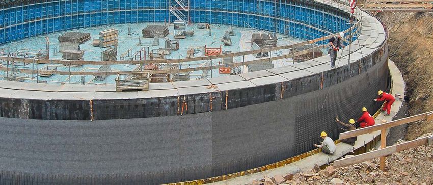
Zemdrain ® – Allgemein / General

Für beste Ergebnisse
Um die besten Ergebnisse mit Zemdrain® Schalungsbahnen                       Inhalt
zu erzielen, sollten nachfolgende Empfehlungen beachtet                      Allgemein . . . . . . . . . . . . . . . . . . . . . . . . . . . . . . . . . . . 3
werden. Sie stellen den gegenwärtigen Stand der Erfah-
rungen dar. Weitere Informationen erhalten Sie über unsere                   Montage der Schalungsbahnen
örtliche Außendienstberatung. Bei speziellen Anforderun-                     Zemdrain® Classic . . . . . . . . . . . . . . . . . . . . . . . . . . . . 9
gen bezüglich des Bauwerkes oder der jeweils eingesetzten                    Zemdrain® Classic vorkonfektioniert . . . . . . . . . . . . . 13
Schalung ist eine Beratung sinnvoll.                                         Zemdrain® Classic Deckenbespannung . . . . . . . . . . . 19
                                                                             Zemdrain® MD . . . . . . . . . . . . . . . . . . . . . . . . . . . . . . 25
Bitte beachten: Wird unter Verwendung von Zemdrain®                          Zemdrain® MD selbstklebend. . . . . . . . . . . . . . . . . . . 31
betoniert, weist der Beton im Allgemeinen eine dunklere
Farbe auf als üblich. Musterflächen entsprechend platzieren!                 Besondere Verarbeitungshinweise . . . . . . . . . . . . . . . 35

Zemdrain® ist ein eingetragenes Warenzeichen von DuPont. www.zemdrain.com

Diese Montageanleitung kann nur als Empfehlung gelten. Sie ersetzt nicht das für die Montage erforderliche Fachwissen.
Die Anleitung wird stets auf dem neuesten Stand der Technik gehalten und wird ständig aktualisiert. Technische Änderun-
gen sind daher – auch ohne vorherige Information des Kunden – ausdrücklich vorbehalten. Die jeweils gültige Version ist
auf unserer Homepage unter: www.maxfrank.de zu finden. Ergänzend gelten unsere Allgemeinen Verkaufsbedingungen.

For best results
In order to obtain the best results with Zemdrain®                           Content
controlled permeability formwork liners, the following                       General . . . . . . . . . . . . . . . . . . . . . . . . . . . . . . . . . . . . 3
recommendations which are based on the current state of
the art should be observed. For the most currrent or further                 Installation of the formwork liners
information and consultation, please contact our local sales                 Zemdrain® Classic . . . . . . . . . . . . . . . . . . . . . . . . . . . . 9
representative. If there are any special requirements with                   Zemdrain® Classic prefabricated . . . . . . . . . . . . . . . . 13
regard to the structure or the formwork to be used, it is                    Zemdrain® Classic for soffit . . . . . . . . . . . . . . . . . . . . 19
recommended to directly contact us for detailed technical                    Zemdrain® MD . . . . . . . . . . . . . . . . . . . . . . . . . . . . . . 25
advice.                                                                      Zemdrain® MD self-adhesive . . . . . . . . . . . . . . . . . . . 31

Please note: Zemdrain® cast concrete will generally be                       Special instructions . . . . . . . . . . . . . . . . . . . . . . . . . . 35
slightly darker than traditionally cast concrete. Please select
the cement type accordingly!

Zemdrain® is a registered trademark of DuPont. www.zemdrain.com

This Installation Guideline is a condensed description of factors having a direct effect on the performance of the FRANK
product and is based on the present state of the art. It may be necessary to alter these recommendations, as more
information becomes available. Correct use is the responsibility of the user, if in doubt please consult your local supplier.

Te c h n o l o g i e s f o r t h e c o n s t r u c t i o n i n d u s t r y                                                                                       3
Zemdrain ® – Allgemein / General

    Allgemeine Hinweise
    Die Zemdrain® Schalungsbahnen Classic und MD müssen              Bereits bespannte Elemente, die noch nicht zum Einsatz
    unter Vorspannung angebracht werden, um einer Faltenbil-         kommen, sind gegen Witterungseinflüsse, insbesondere
    dung durch den hochsteigenden Beton entgegenzuwirken.            Sonneneinstrahlung, zu schützen. Um einen Hitzestau zu
    Auch leichte Kriechvorgänge und thermische Ausdehnung            vermeiden, muss für ausreichende Belüftung gesorgt wer-
    erfordern ein festes Spannen. Es wird empfohlen, das             den. Die mit Zemdrain® belegte Schalung kann in der Regel
    Spannen und Befestigen nach Möglichkeit zu warmen Ta-            wie gewohnt aufgestellt und montiert werden. Zu beachten
    geszeiten vorzunehmen (direkte Sonneneinstrahlung nut-           ist, dass ein großflächiger Schalungsverbund, der mittels
    zen). Das Material wird geschmeidiger und verformungswilli-      Kran verhoben wird, rückseitig mit Querriegel gut ausge-
    ger, die Arbeiten sind dann leichter auszuführen. Sollte nach    steift wird. Bei der Kranaufnahme wird dadurch eine Verwin-
    dem Spannen und Befestigen die Temperatur der Schalung           dung (Durchbiegung) der Schalung und somit eine Entspan-
    um mehr als 10 °C steigen (Verwendung von beheiztem Be-          nung der Zemdrain® Schalungsbahn vermieden.
    ton, heißer Nachmittag), kann die thermische Ausdehnung
    zur Faltenbildung führen.

                                ++

    General information
    The Zemdrain® formwork liners, Classic and MD must be            Formwork elements that have already been lined and are
    attached under pre-tension in order to prevent the liner         awaiting use, must be protected against the weather, in
    from being creased by the rising concrete. A tight tensioning    particular against direct sunlight. Please ensure that there is
    is required due to slight creep processes and thermal            sufficient ventilation in order to avoid heat accumulation. The
    expansion. It is recommended, if possible to carry out the       formwork lined with Zemdrain® can generally be installed
    tensioning and fixing during the warmest part of the day         and erected as usual. It is important that large formwork
    (to make use of the direct sunlight). The liner will become      (particularly assembled panel formwork), which is lifted by
    more flexible and mouldable making installation easier. If the   means of a crane, is held rigid on the rear side using cross
    temperature of the formwork should rise by more than 10 °C       bars. This way, any potential sagging/deformation of the
    after the tensioning and fixing (use of heated concrete, hot     formwork and consequential reduction of the tension in the
    afternoon), the thermal expansion may lead to the liner          Zemdrain® formwork liner can be avoided.
    becoming folded.

4                                                                                                     w w w. m a x f r a n k . c o m
Zemdrain ® – Allgemein / General

Voraussetzung der Schalung                                               Schalungsvarianten
                                                  ®
Die Betonoberfläche ist auch mit Zemdrain das Spiegelbild                Im Prinzip sind alle Schalungen geeignet.
der Schalung. Für optisch anspruchsvolle Oberflächen soll-               Für Zemdrain® Classic wird auf jeden Fall eine Schalung
ten daher möglichst neuwertige Elemente verwendet wer-                   empfohlen, die eine Befestigung durch Tackern erlaubt. Eine
den.                                                                     Trägerschalung aus Holz erzielt erfahrungsgemäß die bes-
Die Schalungsfläche muss glatt, sauber und frei von                      ten Ergebnisse auch hinsichtlich Verwindung, Hitzeentwick-
Trennmitteln bzw. Ölrückständen sein.                                    lung und Befestigung. Für monolithisch hergestellte Rund-
Bei geringwertigen Schalungshölzern sind die Oberflächen                 behälter wird eine Vorkonfektionierung dringend empfohlen.
zu versiegeln, damit kein Holzzucker an die Betonoberfläche              Bei der Verwendung von Stahlrahmenschalungen oder an-
gelangen kann.                                                           deren Rahmenschalungen ist besonderes Augenmerk auf
                                                                         die Schalungsstöße und deren Abdichtung zu richten.
                                                                         Auch bei Zemdrain® MD wird eine Schalung empfohlen, die
                                                                         eine Befestigung durch Tackern ermöglicht. Die Montage
                                                                         mit Klebebändern ist nur eingeschränkt zu empfehlen. Für
                                                                         Schalungen, die keine mechanische Befestigung erlauben,
                                                                         sollte das FRANK Produkt Zemdrain® MD selbstklebend
                                                                         verwendet werden.

       Oil

Formwork requirements                                                        Formwork variants
                                                                ®
The finished concrete surface produced by Zemdrain will                      In principle, all types of supporting formwork elements can
always reflect the profile of the supporting formwork face.                  be used. However, for Classic, we highly recommend the
For aesthetic applications, the use of brand-new elements is                 use of a formwork to which the liner can be easily stapled.
therefore recommended.                                                       The best results can be achieved by using plywood and
The formwork surface must be smooth, clean and free of                       timber faced forms as the fixing is easier and faster. For
release agents, oil residues and other contaminants.                         pre-assembled circular forms, we strongly recommend the
When using lower grade plywood, the surface should                           use of special prefabricated rolls of Classic. When using
always be sealed to prevent the extraction of wood sugars.                   formwork with a steel rame, special attention must be paid
                                                                             to the formwork joints and their proper sealing.
                                                                             For Zemdrain® MD we also recommend the use of formwork
                                                                             to which the liner can easily be stapled. Using adhesive
                                                                             tapes for fixing can only be recommended in certain specific
                                                                             circumstances. When mechanical fixing is not possible then
                                                                             Zemdrain® MD self-adhesive should be used.

Te c h n o l o g i e s f o r t h e c o n s t r u c t i o n i n d u s t r y                                                                  5
Zemdrain ® – Allgemein / General
Vorbereitung der Schalung Spannen und Befestigen
Unbedingt beseitigen, da diese sonst in der Betonober- Um einer möglichen Faltenbildung infolge von Erwärmung
fläche sichtbar sind: durch Sonneneinstrahlung vorzubeugen, ist eine entspre-
■ Positiv auf der Schalhaut vorstehende Erhöhungen chende Vorspannung erforderlich. Locker aufgelegtes Ma-
(Schmutz, Nagelköpfe, usw.) terial verursacht auf der späteren Betonoberfläche Faltenab-
■ nicht verschlossene Ankerlöcher drücke.
■ Vertiefungen und Schlitze Zemdrain® hat eine hohe thermische Ausdehnung, dadurch
können Formänderungen bis zu 1,5 % eintreten. Da die er-
Eine Verschmutzung der Zemdrain® Oberfläche sollte ver- forderliche Spannkraft mit steigender Erwärmung abnimmt,
hindert werden, eine bespannte Schalung nicht mit ver- wirkt sich das Spannen unter Hitzeeinwirkung, wie Sonnen-
schmutzten Schuhen begehen. Beim Erstellen der Schalung einstrahlung oder künstlicher Erwärmung, immer vorteilhaft
ist darauf zu achten, dass das anfallende Überschusswas- aus.
ser kontrolliert abgeleitet wird (Ableitungsöffnungen in den
Schalungen).
Formwork preparation Tensioning and fixing
The following formwork defects must always be repaired An appropriate degree of liner tensioning is required in order
as they will otherwise be reflected on the finished concrete to avoid fold formation. An untensioned liner will cause fold
surface: imprints on the finished concrete surface.
■ any protrusions from the surface, such as mismatched Zemdrain® liners have a high thermal expansion rate that
plywood strips, dirt, nails, etc can cause elongations of up to 1.5 % to occur. Since the
■ unfilled tie bolt holes required tensioning force decreases when the temperature
■ dents and recesses rises, it is always advantageous to carry out tensioning work
under the influence of the warmth of the sun or while using
Precautions should be taken to avoid any contamination artificial heating systems.
of the liner surface before and after fixing. Do not walk
on a covered formwork while wearing dirty shoes. When
assembling the formwork, please ensure sure that any
accumulated water can drain away (drainage openings in
the formwork).
6 w w w. m a x f r a n k . c o mZemdrain ® – Allgemein / General
Spannrichtung
Die Rollen in Hauptspannrichtung abwickeln und in der Re- In horizontaler Richtung genügt eine Vorspannung von ca.
gel vertikal ausrichten (in Betonsteigrichtung). Hier ist eine 0,2 – 0,3 cm/m – abhängig von der bestehenden Lufttem-
Vorspannung von 0,4 bis 0,6 % entsprechend 0,4 – 0,6 peratur.
cm/m notwendig (abhängig von der Lufttemperatur). Die Schalungsbahn zunächst flach auslegen, dann markie-
ren und erst danach den Betrag der Vorspannung nach-
messen.
0,4
cm- 0,6
/m
6
/m-0,
cm,4
0
0,2
cm- 0,3
/m
Tensioning direction
The rolls should as a general rule be unrolled with the length In the cross direction of the roll, an elongation of approx. 2
of the roll, the main tensioning direction, aligned vertically to 3 mm/m is sufficient, depending on the air temperature.
(in the direction in which the concrete rises). Here, an If the cross direction of the roll is also in the vertical pour
elongation of 0.4 to 0.6 % corresponding to 4 to 6 mm/m is direction, then the maximum tension should alway be
required (depending on the air temperature). applied.
Firstly, lay out the formwork liner flat, then mark it and only
remeasure the absolute value of the elongation afterwards.
Te c h n o l o g i e s f o r t h e c o n s t r u c t i o n i n d u s t r y 7Zemdrain ® – Allgemein / General
Stellen und Montage Schalungsstöße
Beschädigungen durch Eisenverleger und lange Stand- Bewährt haben sich hierzu das Zemdrain® Vorlegeband
zeiten bei ungünstiger Witterung vermeiden. Den Arbeits- (ZVBAND), Schaumstoff-Fugenband (FKBANDS), geschlos-
ablauf so wählen, dass der letzte Schalungsschritt die mit senzellige PE-Profile oder entsprechende Dichtmaterialien
Zemdrain® belegte Schalung ist. Nach dem Belegen der aus der Kartusche. Es ist jedoch dabei zu beachten, dass
Schalung sollte diese unmittelbar gestellt und montiert wer- der rückseitige Abfluss von Drainagewasser bei Zemdrain®
den. nicht beeinträchtigt werden darf und die Abdichtungen nach
Zwischen dem Spannen und Betonieren sollte eine der Montage der Schalung nicht in die Betonflächen ragen
möglichst kurze Zeitspanne (max. 3 Tage) liegen, dürfen. Eine Großflächenschalung muss bündig, dicht und
da sich das aufgespannte Material mit der Zeit ent- fluchtend sein.
spannt und dies zur Faltenbildung führt.
Installation Formwork joints
Potential damage arising during steel fixing, formwork The Zemdrain® prefixing tape (ZVBAND) and foam plastic
erection and prolonged periods of disuse during joint tape (FKBANDS) have, due to their closed-cell PE
unfavourable weather conditions must be avoided. Every profiles proved very suitable for sealing formwork joints. It
effort should be made to organise the work process in such is very important however to make sure that water drainage
a way that the Zemdrain® lined forms are put in position as from the rear of the Zemdrain® liner remains unimpeded.
soon as possible after lining and are the last to be erected. Care must be exercised to ensure that the tape does not
protrude from the formwork into the concrete surface. The
It is recommended to keep the time between lining the individual panels of large-scale formwork should always be
formwork and concreting to a minimum (max. 3 days) flush, tight and in alignment.
because the tensioned material will relax over time
and this can lead to fold imprints on the concrete.
8 w w w. m a x f r a n k . c o mZemdrain ® Classic
Zemdrain® Classic
■ Glatte bis leicht strukturierte, graue Oberseite (Betonsei-
te)
■ Rückseite (Schalungsseite) schwarz mit rautenförmigen
Vertiefungen
■ Rollengröße: 1,60 m – 4,20 m Breite und 50 m Länge
■ Für Bespannung von großen Flächen
■ Für die einmalige Verwendung
■ Für Spezialanwendungen, wie z. B. Stahlrundschalungen
bei monolithischer Betonbauweise
Zemdrain® Classic
■ Concrete face- smooth lightly structured grey surface
■ Formwork face - black with rhombical recesses
■ Roll size: 50m long x 1.60 m to 4.20 m wide. Longer rolls
available upon request
■ Suitable for covering of large surfaces
■ Single use
■ For special applications, e.g. convex circular steel form-
work for monolithic concrete construction
Te c h n o l o g i e n f ü r d i e B a u i n d u s t r i e 9Zemdrain ® Classic
Arbeitsvorbereitung Bespannung
Für den Bespannungsvorgang die Schalung auf Gerüstbö- Bitte beachten:
cken oder ähnlichem Unterbau in Waage ablegen. ■ Schwarze Seite zur Schalung – graue Seite zum Beton
Auswahl der Rollenbreite = ■ Tackerklammern aus Edelstahl
Schalungsbreite + mind. 10 cm ■ ausreichend Aussteifungsriegel verwenden (die Schalung
Spannhilfen – wie Spannlift (ZSL0810) - an der Schalung be- darf nicht durchhängen)
festigen.
Zemdrain® abrollen und abschneiden:
■ Bei Verwendung mit Spannlift + 25 cm
■ Bei Verwendung mit Spannzange + 5 cm
Flach auslegen und 10 Minuten relaxieren lassen.
Falls nötig mit sauberem Schalbrett fixieren.
b
+
2x
>
5
cm
+
5
cm
b
+
5
cm
+ 5 cm + 25 cm
!
Preparation for liner installation
For the lining process, the formwork should be laid Please note:
horizontally in both directions on trestles or a similar ■ Black side to formwork – grey side to concrete
substructure. ■ Staples made of stainless steel
Selection of the roll width = ■ Make sure to use sufficient reinforcing cross members
formwork width + not less than 100mm (the formwork must not sag)
Fix the tensioning accessories such as the tensioning
clamps (ZSL0810) onto the formwork.
Unroll and cut Zemdrain®:
■ When using tensioning clamp + 250mm
■ When using tensioning tool + 50mm
Leave it flat for at least 10 minutes to allow the liner to relax
and also warm up in the sun.
If required, hold in position using some clean formwork
boards.
10 w w w. m a x f r a n k . d eZemdrain ® Classic
Spannung in Längsrichtung Schalungslängen über 6 m:
Die Schalungsbahn ist über die volle Breite gleichzeitig zu Zunächst die Schalungsbahn etwa in der Mitte durch eine
spannen. Reihe Tackerklammern an der Schalung fixieren. Danach
■ als Hauptspannrichtung die Betonsteigrichtung bevorzu- die Schalungsbahn an beiden Seiten (oben und unten) mit
gen (Längsrichtung) Spannzange oder Spannliften vorspannen und befestigen.
■ Dehnung 0,4 – 0,6 cm/m (abhängig von der Lufttempe- Überstehendes Material an den Ecken ausklinken.
ratur)
■ Schalungsbahn mittig ausrichten und unten (Bodenseite) Bitte beachten:
mit Tackerklammern aus Edelstahl (Abstand: 2 - 3 cm) Schwarze Seite zur Schalung – graue Seite zum Beton.
befestigen Tackerklammern aus Edelstahl verwenden.
■ Klammerngröße: 10 mm-Klammern bei weicherer, 8
mm-Klammern bei härterer Holzschalungsoberfläche
■ bei Verwendung von Spannliften:
Kantholz 8/10 cm in der Öffnung (U-Profil) befestigen -
Schalungsbahn mit Spannzange faltenfrei straff ziehen
- Kantholz mit 10 mm Klammern befestigen.
/m
/m
cm
cm
6
6
0,
0,
-
-
4
4
0,
0,
0 m m
6,0 6,00
l< l >
8-1
0 mm
/m
cm
6
0,
2-
-
3
4
cm
0,
Lengthwise Tensioning Formwork lengths over 6 m
The formwork liner should be tensioned simultaneously over The formwork liner must first be fixed to the formwork
the complete width. approximately in the middle by using a row of staples.
■ It is always recommended that the lengthwise direction Afterwards, the formwork liner must be pre-tensioned and
of the roll should be vetical (the pour direction). fixed on both sides (top and bottom) using a tensioning tool
■ Align the liner centrally and fix it at the bottom side using or tensioning clamps (ZSL0810). Excess material must be
stainless steel staples at 20 to 30 mm centres notched at the corners.
■ After taking up the slack an elongation of 4 to 6 mm/m
(depending on the air temperature) should be applied Please note:
■ Staple size: 10 mm staples are suitable for most wooden Black side to formwork – grey side to concrete.
forms, 8 mm staples for very hard form surfaces Use staples made of stainless steel.
■ When using tensioning clamps (ZSL0810): Depending on formwork type and tensioning tool used,
Fix the squared timber (80/100mm) in the opening (U stainless steel staples may not be necessary – ask your local
profile), pull the formwork liner tight so that there are no supplyer.
visible folds, affix to the squared timber using 10 mm
staples.
Te c h n o l o g i e n f ü r d i e B a u i n d u s t r i e 11Zemdrain ® Classic
Spannung in Querrichtung
Die Querverspannung (Dehnung 0,2 – 0,3 cm/m – abhän-
gig von der Lufttemperatur) erfolgt mittels Spannzange.
Die Bahn wird mittig von beiden Seiten gleichmäßig und
am besten gleichzeitig mit der Spannzange (ZSZKAZ oder
ZSZMD2500) vorgespannt und mit entsprechender Klam-
merung befestigt.
0,
2-
0,
3
cm
/m
Crosswise Tensioning
The formwork liner should be tensioned evenly over the
complete width.
After taking up the slack an elongation of 2 to 3mm/m
(depending upon air temperature) is applied simultaneously
(starting centrally) on both sides using a tensioning tool
(ZSZKAZ or ZSZMD2500).
For optical reasons, we recommend to position the staples
parallel to the formwork edge or even better outside the
concrete surface.
12 w w w. m a x f r a n k . d eZemdrain ® Classic vorkonfektioniert / prefabricated
Zemdrain® Classic
vorkonfektioniert
Zemdrain® Classic vorkonfektioniert ist eine für die Scha-
lungsinnenseite auf Maß angefertigte Schalungsbahn für
Rundbehälter.
Die spezielle Vorkonfektionierung hilft eine faltenfreie Be-
spannung für Stahl- bzw. Holzrundschalung zu erstellen.
Die Ware wird vorkonfektioniert auf die Baustelle geliefert.
Die Bespannung der Rundschalung ist wie folgt durchzu-
führen:
Behälter bis 4,00 m Höhe können mit nur einer Zemdrain®
Bahn aufgespannt werden. Größere Höhen sind mit zwei
übereinander liegenden Schalungsbahnen herzustellen.
Zemdrain® Classic vorkonfektioniert wird mit Flauschteil und
Abdeckbahn ausgeliefert.
Zemdrain® Classic
prefabricated
Zemdrain® Classic prefabricated is a tailor-made liner for
lining the inner convex surface of special pre-assembled
circular tank forms.
The product is delivered prefabricated to the construction
site.
Prefabrication off-site helps to create a lining for circular
steel and/or wooden formwork which reduces the risk of
fold formation.
Lining of the circular formwork is to be carried out as follows:
Form heights ≤ 4.00 m can be lined using only one
prefabricated sheet.
Form heights 4.00m are lined using two prefabricated
sheets which are overlapped.
Zemdrain® Classic prefabricated is supplied with a special
fleece part with loops, as well as the main prefabricated liner
and a cover liner.
Te c h n o l o g i e s f o r t h e c o n s t r u c t i o n i n d u s t r y 13Zemdrain ® Classic vorkonfektioniert / prefabricated
Aufbringen des Flauschteiles Abrollen der Schalungsbahn
Um die Schalungsbahn später am Bahnstoß zu fixieren, Zum leichteren Abrollen an der Stahlrundschalung wird
das Flauschteil auf Schalung befestigen. Flauschteil mittels die Zemdrain® Rolle auf eine Holzplatte gestellt, an der die
Schraubzwingen vormontieren und anschließend durch Kle- Krankette durch den Rollenkern hindurch befestigt wird.
ben oder Tackern auf der vollen Bahnlänge befestigen.
(A: Kleben - B: Tackern)
Bitte beachten: Die komplett vormontierte und fixierte In-
nenschalung muss absolut frei von Betontrennmitteln sein.
A B
!
Top
Application of the fleece part Unrolling the formwork liner
In order to properly fix the prefabricated liner to the circular In order to make ununrolling of the Zemdrain® roll at the
form, a separate special fleece part must first be fixed in circular steel formwork easier, it is placed on a wooden plate
position. Pre-mount the fleece with loops as shown in 15/1 to which the crane chain is attached by guiding it through
using screw clamps before fixing over the full length by the roll core.
means of gluing or stapling. (A: gluing - B: stapling)
Please note: The fully pre-mounted and fixed inner
formwork must be absolutely free of concrete release
agents.
14 w w w. m a x f r a n k . c o mZemdrain ® Classic vorkonfektioniert / prefabricated
Montage der Schalungsbahn
Die so vorbereitete Zemdrain® Rolle wird nun ca. 15 cm Wenn die Rolle abgewickelt ist, werden Anfang und Ende
überlappend vom Anfang des Flauschteils mittels Schraub- der Zemdrain® Bahn mittels Spanngurten gespannt. Man
zwinge fixiert und mit der Kranvorrichtung um die Stahl- beginnt nun von unten mit dem Ausrichten der Bahn und
rundschalung geführt. Eine zusätzliche dem Anbringen der Spanngurte. Beim Spannen ist darauf
Sicherung der Schalungsbahn durch Schraubzwingen alle zu achten, dass immer der übernächste Gurt gespannt wird
4-5 m ist während der Abwicklung sehr hilfreich. und dann die dazwischen liegenden Gurte. Gespannt wird
in mehreren Schritten.
Achtung:
Schraubzwingen müssen während des Spannvorgangs ent-
fernt werden.
½ ½
ca. 15 cm 4
2
5m
ca. 4-
3
1
Installation of the formwork liner
Before unrolling ensure that the Zemdrain® roll overlaps the After being completely unrolled, the two ends of the
special fleece with loops by circa 150mm. Starting at the Zemdrain® formwork liner must be joined for tensioning.
beginning of the fleece hold liner in position using a screw The next step is therefore to align the two sections of liner
clamp and then guide the roll around the circular steel and to attach the tensioning belts starting at the bottom.
formwork with the crane device. Additional screw clamps When tensioning, make sure that alternate belts are always
to support the unrolled liner should be attached every 4 to tensioned first before tensioning the belts located in
5 m. between. The tensioning is carried out in several gradual
steps to ensure an even tension is applied.
Caution:
The screw clamps must be removed during the tensioning
process.
Te c h n o l o g i e s f o r t h e c o n s t r u c t i o n i n d u s t r y 15Zemdrain ® Classic vorkonfektioniert / prefabricated
Nach dem Spannvorgang Abschneiden des Ösenteils
Die Sicherungsfäden lösen und die Schutzfolie vom vorkon- Das Ösenteil mit dem eingelegten Stahlband kann mit
fektionierten Zemdrain® entfernen. Durch gleichmäßiges An- einem einfachen Messer abgeschnitten werden.
drücken der Schalungsbahn verhakt sich nun das Flausch-
teil auf der Schalung mit dem Hakenteil am Zemdrain®.
!
Top
After the tensioning Cutting the eye part
Loosen the safety threads and remove the protective film Once the liner is firmly held in position, the eyelets with the
®
from the back surface of the prefabricated Zemdrain steel band should be carefully cut off using a kraft knife,
exposing the special backing with hooks. By evenly pressing taking care not to damage the fleece.
the formwork liner on to the special fleece part with loops,
a secure bond is formed to hold the liner in place in tension.
16 w w w. m a x f r a n k . c o mZemdrain ® Classic vorkonfektioniert / prefabricated
Befestigung der Abdeckbahn
Die mitgelieferte, vorkonfektionierte Zemdrain® Classic Ab- Die Innenschalung des Stahlrundbehälters ist nun fertig be-
deckbahn wird über die Stoßstelle gebracht und mittels spannt und es kann die Stahlamierung aufgestellt werden.
doppelseitigem Klebeband aufgeklebt (Variante A) bzw. bei
Holzschalung fest getackert (Variante B).
B
A
Fixing the cover liner
After removal of the eyelets, the gap between the ends of The top edge of the liner can now be temporarily supported
®
the prefabricated Zemdrain must be covered. The supplied at regular intervals by clamping or stapling to the form to
piece of Classic cover liner is positioned above the joint and prevent sag. The internal formwork of the circular steel
glued on using double-sided adhesive tape (variant A) and/ form is now fully lined and the steel reinforcement can be
or stapled when using a wooden formwork (variant B). installed.
Te c h n o l o g i e s f o r t h e c o n s t r u c t i o n i n d u s t r y 17Zemdrain ® Classic vorkonfektioniert / prefabricated
Betoniervorgang Rundbehälter mit Wandhöhen > 4,00 m
Beim Betoniervorgang ist darauf zu achten, dass das obe- Bei Behältern über 4,00 m Höhe ist der gleiche Bespann-
re Ende des Zemdrain® freigegeben wird, (Schraubzwingen vorgang mit 10 cm Überlappung zu wiederholen.
bzw. Tackerklammern müssen entfernt werden),
damit eventuell aufstauende Falten nach oben hin auslaufen
können.
2
>4m
10 cm
4 -5 m
1
Concreting operation Circular forms with wall heights > 4.00 m
During the concreting operation, care must be taken in order For forms with a height of more than 4.00 m, the lining
®
to ensure that the upper end of the Zemdrain is free to operation is to be repeated with an overlap of 100mm.
move (any screw clamps and/or staples used to retain liner
in position must be removed) so that any folds that might
develop in the surface of the liner can be smoothed towards
the top by the advancing concrete.
18 w w w. m a x f r a n k . c o mZemdrain ® Classic Deckenbespannung / covering for soffits
Zemdrain® Classic
Deckenbespannung
Die Deckenbespannung kann nur mit Zemdrain® Classic
ausgeführt werden, langjährige Erfahrungen in der Praxis
haben dies bestätigt. Eine faltenfreie Bespannung ist mit
einer maximalen Bahnbreite von 2,25 m mit der Decken-
spannvorrichtung durchführbar.
Auf eine saubere Ausführung der Überlappung und Befes-
tigung der einzelnen Bahnenstöße ist zu achten, so dass
es zu keinem Hinterlaufen der Zemdrain® Schalungsbahn
kommt.
Zemdrain® Classic
covering for soffits
Lining of soffits is best carried out using Zemdrain® Classic,
although Zemdrain® MD may also be used in special
circumstances, but only after consultation with our Technical
Department.
For the soffit of water tanks a surface that is free of folds can
best be achieved using rolls with a maximum width of 2.25
m and a special fixing device. For bridge soffits widths of up
to 4.2m are practical and flat lengths of up to circa 48m can
be tensioned in one length with special fixing tools, please
consult our Technical Department.
It is very important that the overlapping and the fixing of
the individual liner joints are properly executed so that any
concrete grout or fines are prevented from getting behind
the liner.
Te c h n o l o g i e s f o r t h e c o n s t r u c t i o n i n d u s t r y 19Zemdrain ® Classic Deckenbespannung / covering for soffits
Spannrichtung und Spannkraft Anordnung der Längsstöße
Für die Bespannung von Deckenschalungen, insbeson- Die Längsstöße der Schalungsbahnen so festlegen, dass
dere bei Trinkwasserbehältern, wird die Verwendung von die Stützenanschlüsse etc. im Längsstoßbereich liegen.
®
Zemdrain Classic empfohlen.
Die maximale Bahnbreite sollte 2,25 m nicht überschreiten.
Die erforderliche Vorspannung von 0,4 – 0,6 cm/m der
Schalungsbahnenlänge (Abwickelrichtung) ist unbedingt
herzustellen, optimal wären bis zu 0,8 cm/m.
Achtung:
Die Befestigungsklammern dürfen jedoch nicht ausreißen!
m
cm/ /m)
- 0,68 cm
0, (0,
4
<
2
,2
5
m
Tensioning direction and tensioning force Arrangement of the longitudinal joints
For the lining of soffit formwork, in particular with regard to The longitudinal joints of the formwork liners must be
®
drinking water reservoirs, the use of Zemdrain Classic is arranged in such a way that the joint connections etc. are
recommended. located in the longitudinal joint area.
The maximum liner width for this application should not
exceed 2.25 m.
It is mandatory that the required pre-tensioning of 4 to 6
mm/m in the lengthwise direction of the roll is achieved. The
optimal tension would be 8 mm/m.
Caution:
The staples must not be torn out!
20 w w w. m a x f r a n k . c o mZemdrain ® Classic Deckenbespannung / covering for soffits
Auslegen der Schalungsbahn
Schalungsbahn auslegen und ca. 10 Minuten relaxieren las- Obere Schalungsbahn ausrichten und an einem Ende fixie-
sen, anschließend die Schalungsbahn straff und faltenfrei ren. Um ein Hinterlaufen zu verhindern sollte der Tackerab-
befestigen. stand ca. 2-3 cm betragen.
Beim zu überlappende Stoß der unteren Bahn ist ein Tacke-
rabstand von ca. 10 - 15 cm völlig ausreichend. Achtung:
Der Überlappungslängsstoß beider Bahnen ist sorgfältig
Achtung: auszuführen, um ein Hinterlaufen der Schalungsbahn zu
Schwarze Seite Schalung, graue Seite Beton. verhindern.
++
ca m
3c
.
. .
ca 5 cm ca cm
1 3
Laying out the formwork liner
Lay out the first sheet of liner flat and allow it to relax for Align the next sheet of liner and after fixing at one end,
at least 10 minutes. Then, take up the slack, tension and redo the steps as for the first sheet.. In order to prevent
affix liner in accordance with these guidelines for a fold free any cement fines or grout from getting behind the liner,
surface. the upper sheet should be stapled down at 20 to 30mm
For the the joint that is to be covered by the next sheet of centres.
liner, staple down along the edge at approx, 100 to 150mm
centres. Caution:
The overlapping longitudinal joint of both liners is to be
Caution: properly executed in order to prevent any material from
Black side to formwork, grey side to concrete. getting behind the liner.
Te c h n o l o g i e s f o r t h e c o n s t r u c t i o n i n d u s t r y 21Zemdrain ® Classic Deckenbespannung / covering for soffits
Spannen mit Spannvorrichtung
Bei Verwendung einer Deckenspannvorrichtung wird ein Vorspannen der Schalungsbahn bis zum vorgesehenen
Kantholz 8/10 cm in der Öffnung (U-Profil) befestigt. Maß.
Schalungsbahn straff und faltenfrei am Kantholz 8/10 cm
mit 10 mm Klammern befestigen.
Achtung:
Besonders bei Rundbehältern auf ausreichende Restlänge
achten.
m
c m/ )
m
- 0,6 cm/
0,4 (0,8
Tensioning with tensioning device
When using a soffit fixing device, a squared timber Tension the formwork liner up to the specified extent.
(80/100mm) is to be fixed in the opening of the U profile.
The liner should be tightly attached to this squared timber
ensuring no folds develop using 10 mm staples.
Caution:
Make sure that there is a sufficient residual length, especially
with regard to circular forms.
22 w w w. m a x f r a n k . c o mZemdrain ® Classic Deckenbespannung / covering for soffits Tackern der Schalungsbahn Befestigen der Schalungsbahn vor der Spannvorrichtung. Nach dem Entfernen der Spannvorrichtung, die Schalungs- Eine zusätzliche Tackerreihe im 90° Winkel zur Abwick- bahn stramm auslegen und Überstände abschneiden.. lungsrichtung erleichtert das faltenfreie Bespannen mittels Spannvorrichtung. Stapling the formwork liner Staple the liner in place as close to the tensioning device as After the tensioning device has been removed, lay out the possible. formwork liner in a tight manner and cut off any excess The row of staples runs at 90° angle to the unrolling direction lengths. and staple should be at maximum 30mm centres. Te c h n o l o g i e s f o r t h e c o n s t r u c t i o n i n d u s t r y 23
Zemdrain ® Classic Deckenbespannung / covering for soffits

     Randbereich befestigen
     Reststück stramm und faltenfrei am Rand der Schalung be-     Mit der nächsten Schalungsbahn fortfahren.
     festigen, eventuell Überstände abschneiden.                  Bei längerer Standzeit empfehlen wir im Abstand von ca.
                                                                  2-3 m in Querrichtung die einzelnen Schalungsbahnen
                                                                  durch eine zusätzliche Klammerreihe zu sichern.

                                                                                     m
                                                                                   3
                                                                                2-

     Fixing the edge area
     Fix the remaining piece to the edge of the formwork in a     Proceed with the next section of liner.
     tight and fold-free manner and cut off any existing excess   In the event of prolonged periods of disuse, we recommend
     lengths.                                                     to secure the individual formwork liners by adding an
                                                                  additional row of staples in the transverse direction at
                                                                  approx. 2 to 3 m along the length of the roll.

24                                                                                                 w w w. m a x f r a n k . c o m
Zemdrain ® MD
Zemdrain® MD
■ Zemdrain® MD ist für den mehrmaligen Einsatz vorgese-
hen
■ glatte bis leicht strukturierte weiße Oberseite (Betonseite)
Rückseite (Schalungsseite) mit speziellem Entwässe-
rungsgitter
■ Rollengröße: 2,50 m Breite und 35 m Länge
■ Hohe Wirtschaftlichkeit durch möglichen mehrmaligen
Einsatz (2-3 mal) und durch einfachen, schnellen Einbau
Zemdrain® MD
■ Zemdrain® MD is a multiple use liner
■ Concrete face - smooth or lightly structured white upper
side
■ Formwork face – side with special drainage grid
■ Roll size: 2.50 m wide and 35 m long
■ Very cost effective due to simple and quick installation
whilst multiple uses are possible (2 to 3 times)
Te c h n o l o g i e s f o r t h e c o n s t r u c t i o n i n d u s t r y 25Zemdrain ® MD
Zuschneiden der Schalungsbahn Spannen vertikal
Die Schalung auf Gerüstböcken oder ähnlichem Unterbau Die Schalungsbahn ist über die volle Breite gleichmäßig zu
absolut waagrecht in beiden Richtungen für den Bespan- spannen.
nungsvorgang ablegen.
Achtung: A: Spannen mit Spannzange MD (ZSZMD2500)
Ausreichend Aussteifungsriegel verwenden. Schalung darf B: Spannen mit Spannlift (ZSL0810)
sich bei Kranbetrieb nicht durchbiegen oder verwinden.
■ Zemdrain® MD abrollen und abschneiden Achtung: Glatte Seite ist Betonseite.
■ Erforderliche Überstände je Seite:
■ bei Verwendung von Spannzange: + 5 cm
■ bei Verwendung von Spannlift: + 25 cm
■ Flach auslegen und 10 Minuten relaxieren lassen.
■ Schalungsbahn mittig ausrichten und an einer Seite
befestigen.
■ Es werden 8-10 mm Tackerklammern in einem Abstand
von 2 – 3 cm empfohlen.
b
+
2x
>
+
5
cm
5
cm
A
5
c
m
b
+
2
5
5
cm
cm
+ 5 cm + 25 cm
!
B
Preparation for liner installation Lengthwise tensioning
For ease of fixing, place the formwork on trestles or a similar In the length of the roll: once the slack has been taken up,
substructure in a position that is absolutely horizontal in both an elongation of 3 to 6mm/m is applied. The formwork liner
directions. must be tensioned evenly over the complete width
Caution:
Make sure to use sufficient reinforcing cross members to Tensioning devices
prevent the formwork from sagging or deforming during craning. A: Tensioning using the tensioning tool (ZSZMD2500)
■ Unroll and cut Zemdrain® MD to size. B: Tensioning using tensioning clamps (ZSL0810)
■ Required excess lengths per side: Caution: The smooth side is the concrete side.
■ When using a tensioning tool: + 50mm
■ When using tensioning clamps: + 250mm
■ Leave it flat for at least 10 minutes to allow the liner to
relax and warm in the sun.
■ Centrally align the formwork liner and staple down at the
non-tensioning end.
■ Liner to be stapled in position using 8 to10 mm staples at
20 to 30mm centres.
26 w w w. m a x f r a n k . c o mZemdrain ® MD
Querverspannung
Hauptspannrichtung: Dehnung 0,4 – 0,6 cm/m Die Querverspannung (Dehnung 0,1 – 0,2 cm/m) wird mit
Die Schalungsbahn ist über die volle Breite gleichmäßig zu der Spannzange (ZSZKAZ oder ZSZMD2500) auf beiden
spannen. Dafür sollen Hilfsmittel wie Spannzange (L = 2,50 Seiten gleichzeitig durchgeführt oder abschnittsweise (ca. 1
m) oder Spannlift verwendet werden. m) abwechselnd links und rechts gezogen.
Bei einer Schalungslänge über 6 m, zunächst die Scha- Aus optischen Gründen sollen die Tackerklammern parallel
lungsbahn in der Mitte durch eine Reihe Tackerklammern an zur Schalungskante oder besser außerhalb der Betonfläche
der Schalung fixieren. Danach die Schalungsbahn an bei- gesetzt werden.
den Seiten mit Spannzange oder Spannliften vorspannen
und befestigen.
m
cm/
,6
-0
0,3
0 m
6,0
l >
0, cm
1- /m
0,
2
m
m/
8-1
0 mm
,6 c
-0
0,3
Formwork lengths up to 3 m Crosswise tensioning
Tensioning tool (ZSZMD2500) and tensioning clamp The formwork liner is to be tensioned evenly over the
(ZSL0810) can both be used to apply the required elongation complete width.
of 3 to 6mm/m. Crosswise tensioning: after taking up the slack an elongation
of 1 to 2 mm/m is applied simultaneously on both sides
Formwork lengths greater than 3m using a tensioning tool (ZSZKAZ or ZSZMD2500) at intervals
Tensioning tool (ZSZMD2500) can also be used for lengths of approx. 1 metre, alternating between sides.
up to 6.0m, however the liner must first be fixed to the
formwork approximately in the middle by using a row of For optical reasons, we recommend to position the staples
staples. The liner is then tensioned and fixed on both sides parallel to the formwork edge or even better outside the
(top and bottom). Any excess material must be notched at concrete surface.
the corners. Alternatively a tensioning clamp (ZSL0810) can
be used without the central row of staples for lengths of up
to 12m.
Te c h n o l o g i e s f o r t h e c o n s t r u c t i o n i n d u s t r y 27Zemdrain ® MD
Abkantung Schalungsstöße
Anwendungen mit Überstand: Überstand der Schalungsbahn vorkanten und an der Stirn-
seite mit einem doppelseitigen Klebeband (ZDSSKB) befes-
®
Den Überstand des Gitters vom Zemdrain Vlies trennen. tigen.
Anschließend das Gitter an der Schalungskante abschnei-
den.
1 3
2
Closing formwork edges
Applications with excess lengths: Fold down the excess length of the formwork liner and
fix it to the front side using double-sided adhesive tape
Separate the excess grid from the Zemdrain® fleece. Then, (ZDSSKB) or staple in position.
cut off the grid at the formwork edge.
28 w w w. m a x f r a n k . c o mZemdrain ® MD
Abdichtung der Schalungsstöße
Alternativ sind folgende Abdichtungen der Zemdrain® MD- Bei bündigem Schnitt ist ein Schaumstoff-Fugenband zu
Ränder gebräuchlich: verwenden.
1. Das vorherige Hinterlegen eines Schaumstoff-Fugenban-
des. (FKBANDS) Achtung:
®
2. Abkleben der Ränder mittels FRANK Zemdrain Abdeck- Nicht am unteren Ende und in Trinkwasserobjekten verwen-
band. (ZEBAND) den!
1
2
Sealing the formwork joints
Alternatively, the following sealing method for Zemdrain® MD A foam plastic joint tape is to be used for flush cuts.
edges are generally applied:
1. Fix a foam plastic joint tape underneath the liner Caution:
beforehand (FKBANDS). When constructing drinking water structures, please consult
2. Seal the edges with the Zemdrain® cover tape (ZABAND local regulations on the use of adhesive tapes!
or ZEBAND).
3. Tape use - Do not use at bottom edge of form as water
drainage may ne impeded.
Te c h n o l o g i e s f o r t h e c o n s t r u c t i o n i n d u s t r y 2930 w w w. m a x f r a n k . c o m
Zemdrain ® MD selbstklebend / self-adhesive

                                                                         Zemdrain® MD
                                                                         selbstklebend
                                                                         Zemdrain® MD selbstklebend ist eine Ergänzung zu den be-
                                                                         kannten kontrolliert wasserabführenden Schalungsbahnen
                                                                         Zemdrain® Classic und Zemdrain® MD.

                                                                         Auf Grund der besonderen Befestigungsmöglichkeit kommt
                                                                         Zemdrain® MD selbstklebend in speziellen Fällen zum Ein-
                                                                         satz:

                                                                         ■   Befestigung ist mit Klammern auf Schalungsoberflächen
                                                                             nur bedingt
                                                                         ■   oder überhaupt nicht möglich (Stahl oder harter Kunst-
                                                                             stoff)
                                                                         ■   Befestigung auf Schalungen mit besonderen geometri-
                                                                             schen Formen
                                                                         ■   Befestigung ohne sichtbare Klammern
                                                                         ■   Befestigung auf kleinen Schalungseinheiten

                                                                         Achtung:
                                                                         Zemdrain® MD selbstklebend ist nicht im Trinkwasserbe-
                                                                         reich geeignet.

                                                                         Zemdrain® MD
                                                                         self-adhesive
                                                                         Zemdrain® MD self-adhesive is the newest addition to the
                                                                         range of Zemdrain® controlled permeability formwork liners
                                                                         which includes Zemdrain® Classic and MD.

                                                                         Zemdrain® MD self-adhesive is generally used for special
                                                                         applications, but may also be used for standard applications.

                                                                         ■   for formwork where stapling is very difficult or impossible
                                                                             (steel or hard plastic).
                                                                         ■   for formwork with special geometrical shapes
                                                                         ■   for fixing without visible fixing marks
                                                                         ■   for small-sized formwork panels

                                                                         Caution:
                                                                         When proposing to use Zemdrain® MD self-adhesive for
                                                                         drinking water applications, please consult your local
                                                                         regulations first.

Te c h n o l o g i e s f o r t h e c o n s t r u c t i o n i n d u s t r y                                                                 31
Zemdrain ® MD selbstklebend / self-adhesive
Material ablegen und abrollen Material ansetzen und fixieren
Die Schalung auf Gerüstböcken oder ähnlichem Unterbau Zemdrain® MD selbstklebend ansetzen und auf gleichen
absolut waagrecht in beiden Richtungen ablegen. Überstand achten.
Schutzfolie abziehen und leicht andrücken.
Achtung:
Ausreichend Aussteifungsriegel verwenden.
Zemdrain® MD selbstklebend abrollen und mit Überstand
x > 5 cm abschneiden.
Flach auslegen und 10 Minuten relaxieren lassen.
b
+
2x
>
5
cm
+
5c
m
cm
5
+
+
b
5c
m
!
Preparing the liner for installation Applying and fixing the material
Place the formwork on trestles or a similar substructure in a Apply Zemdrain® MD self-adhesive and make sure that the
position that is absolutely horizontal in both directions. excess length is even at all edges.
Remove the protective film and press the liner on slightly.
Caution:
Make sure to use sufficient reinforcing cross members.
Unroll Zemdrain® MD self-adhesive and cut it off with an
excess length of: x > 50mm.
Leave it flat for at least 10 minutes to allow the liner to relax
and warm up.
32 w w w. m a x f r a n k . c o mZemdrain ® MD selbstklebend / self-adhesive
Material anpressen Schützen der Ränder
®
Anschließend wird Zemdrain MD selbstklebend durch Das Gitter im Bereich des Überstandes vom Vlies zu tren-
Druck mit der Gummirolle (ZGROLL) in der Fläche, und vor nen und genau am Schalungsrand abschneiden, damit die
allem an den Rändern an der Schalung fixiert. Je höher der Ränder zusätzlich geschützt werden und optisch schönere
Druck, desto besser die Verklebung. Schalungsstöße entstehen.
Achtung:
Die mit Zemdrain® MD selbstklebend belegten Schalungen
müssen vor starker Überhitzung durch Sonneneinstrahlung
geschützt werden (> 50 °C Schalungsoberflächentempera-
tur). Bereits Lufttemperaturen über 25° C können Schalun-
gen, die der direkten Sonneneinstrahlung ausgesetzt sind,
so stark aufheizen, dass die Klebekraft stark abnimmt.
1
++
2
Pressing on the material Protection of the edges
Zemdrain® MD self-adhesive is then firmly fixed to the The grid is to be separated from the fleece in the area of the
surface and especially to the edges of the formwork by excess length and then cut off exactly at the formwork edge
applying pressure using the rubber roller (ZGROLL). The so that the edges are additionally protected and to obtain
higher the pressure, the better the glued connection will be. the most aesthetic formwork joints.
Caution:
Formwork lined with Zemdrain® MD self-adhesive must
be protected against excessive overheating caused by
direct sunlight (> 50° C formwork surface temperature). Air
temperatures of only 25° C can already heat up formwork,
which is exposed to direct sunlight, to such an extent that
the adhesive strength is greatly reduced.
Te c h n o l o g i e s f o r t h e c o n s t r u c t i o n i n d u s t r y 33Zemdrain ® MD selbstklebend / self-adhesive
Befestigung mit Klebeband Auswechseln von Zemdrain® MD selbst-
Das überstehende Vlies vorkanten (reduziert die Rückstell- klebend
kraft) und mit FRANK Spezialklebeband (ZDSSKB) an der Um Zemdrain® MD selbstklebend von der Schalung abzu-
Stirnseite der Schalung befestigen. ziehen, wickelt man die Schalungsbahn auf ein Kantholz
und nimmt das Abziehdrehkreuz zur Hilfe. Sollten Kleberres-
te auf der Schalungsoberfläche verbleiben, diese mit dem
FRANK Zemdrain® Kleberex (ZKLEX) einsprühen und an-
schließend mit einer Spachtel entfernen.
Achtung:
Vor der erneuten Verlegung von Zemdrain® MD selbst-
klebend muss die Schalungsoberfläche wieder gründlich
gereinigt werden, Kleberrückstände, lose Partikel, Öl und
Feuchtigkeit entfernen.
3
Fixing with adhesive tape Removing Zemdrain® MD self-adhesive
Fold down the overhanging fleece (reduces the restoring In order to remove Zemdrain® MD self-adhesive from the
force) and fix it to the front side of the formwork using formwork, the formwork liner should to be wound up on a
FRANK special adhesive tape (ZDSSKB) or staples. squared timber while using the removal tool to support the
process. If glue residues remain on the formwork surface,
spray them with FRANK Zemdrain® Kleberex (ZKLEX) and
remove them using a scraper afterwards.
Caution:
Before using Zemdrain® self-adhesive again, the formwork
surface must be thoroughly cleaned and glue residues,
loose particles, oil and water removed.
34 w w w. m a x f r a n k . c o mZemdrain ® – Besondere Verarbeitungshinweise / Special instructions
Besondere Verarbeitungs-
hinweise zu Zemdrain®
Produkten
Special instructions for
Zemdrain® Controlled
Permeability Formwork
Liners
Te c h n o l o g i e s f o r t h e c o n s t r u c t i o n i n d u s t r y 35Zemdrain ® – Besondere Verarbeitungshinweise / Special instructions
Klammern Abstandhalter
Nur rostfreie Klammern (Edelstahl) in ausreichender Größe. Abdrücke reduzieren – Last verteilen
Es sind nur rostfreie Klammern und Klammern in ausrei- Um sichtbare Abdrücke, z. B. durch Abstandhalter an der
chender Größe (8 - 12 mm) zu verwenden. Vorstehende späteren Betonoberfläche zu vermeiden, sollte der maxi-
Klammern sind mit dem Hammer nachzuklopfen, ansonsten male Druck auf die Zemdrain® Schalungsbahn nicht zu groß
besteht die Gefahr, dass diese im Beton verbleiben. sein (nicht mehr als 200 N/cm²). Wir empfehlen daher, die
Last der Bewehrung auf möglichst viele FRANK Flächen-
abstandhalter Dreikant Konkav mit Haken (Typ: FAHDH) mit
größerer Aufstandsfläche zu verteilen.
8-1
mm2
Staples Spacers
Only use stainless steel staples of the correct size 8-12 mm. Reduction of visible imprints – load distribution
Protruding staples must be hammered home, otherwise To avoid visible marks on the finished concrete surface, for
they may remain in the face of the concrete. example caused by spacers, the maximum pressure applied
to the Zemdrain® formwork liner should not be more than
2 MPa. To give as large a contact area as possible, we
therefore recommend to distribute evenly the load caused
by the reinforcement onto a regular grid of FRANK extruded
fibre concrete spacers (type: FAHDH triangular concave
with hook).
36 w w w. m a x f r a n k . c o mZemdrain ® – Besondere Verarbeitungshinweise / Special instructions
Spannanker Beschädigungen
®
Nach Befestigung von Zemdrain auf der Schalung. Reparatur auch bei größeren Flächen möglich.
Die Löcher für die Schalungsanker sollten erst dann bear- Bei größeren Flächen ist es möglich ein neues Stück
beitet werden, wenn Zemdrain® endgültig auf der Schalung Zemdrain® auf die verletzte Stelle zu legen und durch beide
befestigt ist. Es ist im Allgemeinen ausreichend, mit dem Flächen hindurch auszuschneiden. Das verletzte Teilstück
Klingenmesser einen kreuzförmigen Schlitz einzuschneiden. wird herausgenommen und das neue Stück mit Tacker-
Zusätzlich sollten Tackerklammern um die Spannstelle ge- klammern eingesetzt.
setzt werden.
Achtung:
Im Trinkwasserbereich keine selbstklebenden Materialien
verwenden, Zemdrain® MD nur mit Vlies reparieren.
Tie bars Damages
After fixing Zemdrain® to the formwork. Repairs are also possible on larger surfaces.
The tie bolt holes should only be made after Zemdrain® has Place a new piece of Zemdrain® over the damaged area
been fully tensioned and fixed to the formwork. It is generally and cut through both layers to form an infill section. Remove
sufficient to make a cross-shaped slit using a blade cutter. the damaged liner and replace it with the new piece using
For extra safety, a few staples can be used to secure the staples or tape.
liner in place at the locations.
Caution:
The use of self-adhesive materials for drinking water
applications may be subject to local restrictions. Only repair
Zemdrain® MD using fleece material.
Te c h n o l o g i e s f o r t h e c o n s t r u c t i o n i n d u s t r y 37Zemdrain ® – Besondere Verarbeitungshinweise / Special instructions
Betonieren Verdichten
Im Einklang mit den üblichen Richtlinien Verdichten mit einem Innenrüttler
Die Auswahl der Betonsorte, der Einbau des Betons und Übermäßiges und unregelmäßiges Rütteln kann zur Entste-
das Verdichten sollte im Einklang mit den üblichen Richtli- hung von Farbunterschieden führen. Verdichter, die zu lan-
nien erfolgen. ge an einer Stelle rütteln, treiben Zementpartikel durch das
Bei der Verwendung von Betonsorten mit Ölschiefer- Zemdrain®. Diese Partikel fehlen der Oberfläche und führen
zementen oder mit einem hohen Silicaanteil halten zu partieller Absandung. Außerdem erhöht sich der Reini-
Sie bitte Rücksprache mit unserer Anwendungstech- gungsaufwand für die Schalung.
nik. Der Rüttler sollte in einem Abstand von mindestens 5 - 10
Um Farbunterschiede in Grenzen zu halten, sollten Verzöge- cm zur Schalungsfläche geführt werden, sobald die Haupt-
rungen zwischen dem Einfüllen der einzelnen Schüttlagen verdichtung abgeschlossen ist.
vermieden werden. Betonfeuchte Schalungsbahnen dür- Als Verdichtungsgerät haben sich Innenrüttler bewährt. Au-
fen nicht austrocknen, da sonst mit der Abzeichnung von ßenrüttler können zu punktuellen Unterschieden in der Be-
Schüttfugen am fertigen Bauteil zu rechnen ist. Beste Er- tonfläche führen.
gebnisse erreicht man mit einem unterhalb der Betonober- Die oberen 10 cm von vertikalen Betonflächen können Po-
fläche eingetauchten Schüttrohr oder Pumpenschlauch bei ren und eine hellere Färbung des Betons aufweisen. Durch
gleichzeitiger Verdichtung des soeben einlaufenden Betons. eine Nachverdichtung des Betons in diesem Bereich kann
Zementschlämme, die durch den herabfallenden Beton an man das verhindern, das ist bei geneigten Konterschalun-
®
Zemdrain gespritzt wird, verhindert ganz oder teilweise das gen besonders wichtig. Eine andere Möglichkeit besteht da-
Abführen von Luft und Wasser. Desweiteren können diese rin, durch Überbetonieren die Betonauflast zu erhöhen.
Spritzer absanden oder kreiden.
Concreting Compaction
Concrete practice should conform to standard guidelines Compaction with an internal vibrator should always be
the primary vibration method. The internal vibrator should
Concrete should be selected, placed and compacted in be kept at a distance of at least 50 to 100mm from the
accordance with local guidelines. formwork surface at all times. External vibrators should only
If using a concrete with a special cement, such as oil be used as a secondary means of vibration as their use can
shale cement or cement with a high percentage of cause blemishes on some parts of the concrete surface.
silica, please discuss in advance with our technical
department. Excessive and irregular vibration can result in colour
To minimize the potential for colour variations, delays variations. Vibrators that are used on one spot for too long
between individual pour layers should be avoided. Prevent may also drive cement fines through the Zemdrain® resulting
concrete from wetting the surface of the liner and from in a partial sanding of the finished surface. The excess fines
being allowed to dry out to avoid prominent pour lines on on the formwork surface will require more intensive cleaning.
the finished surface. The best results can be achieved by Some blowholes and a lighter coloured concrete can often
submerging a tremie pipe or a pump hose underneath the occur in the upper 100mm of a pour, particularly when using
concrete surface while simultaneously compacting the inclined top forms.This can be minimized by re-vibration of
inflowing concrete. Splashes of cement laitance against this zone (after 20-50 minutes), followed by tamping and
Zemdrain® caused by the falling concrete can completely or smoothing of the surface. Another possibility is to surcharge
partly prevent discharge of air and water. the surface.
38 w w w. m a x f r a n k . c o mSie können auch lesen