3D-Druck des Hochleistungskunststoffes Polyetheretherketon (PEEK)
←
→
Transkription von Seiteninhalten
Wenn Ihr Browser die Seite nicht korrekt rendert, bitte, lesen Sie den Inhalt der Seite unten
Aus der Poliklinik für Zahnärztliche Prothetik

    der Ludwig-Maximilians-Universität München

3D-Druck des Hochleistungskunststoffes

     Polyetheretherketon (PEEK)

                    Dissertation

    zum Erwerb des Doktorgrades der Zahnmedizin

          an der Medizinischen Fakultät der

    Ludwig-Maximilians-Universität zu München

                    vorgelegt von

                 Alexander Prechtel

                         aus

                      München

                        2020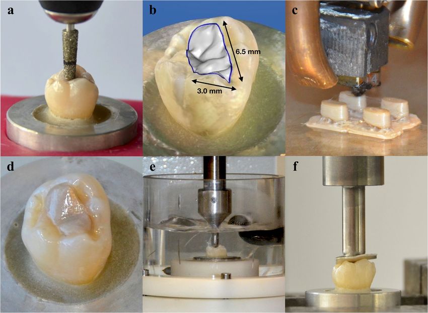
Mit Genehmigung der Medizinischen Fakultät der Universität München

Erster Gutachter:                     Prof. Dr. Dipl.-Ing. (FH) Bogna Stawarczyk, M.Sc.

Zweiter Gutachter:                    Prof. Dr. med. dent. Daniel Edelhoff

Dritter Gutachter:                    Prof. Dr. med. dent. Andrea Wichelhaus

Mitbetreuung durch den
promovierten Mitarbeiter:             Dr. med. dent. Marcel Reymus

Dekan:                                Prof. Dr. med. dent. Reinhard Hickel

Tag der mündlichen Prüfung:           04.06.2020
Promotionsbüro
                               Medizinische Fakultät

                                      Eidesstattliche Versicherung

Prechtel, Alexander
Name, Vorname

Ich erkläre hiermit an Eides statt,

dass ich die vorliegende Dissertation mit dem Titel

3D-Druck des Hochleistungskunststoffes Polyetheretherketon (PEEK)

selbständig verfasst, mich außer der angegebenen keiner weiteren Hilfsmittel bedient und alle
Erkenntnisse, die aus dem Schrifttum ganz oder annähernd übernommen sind, als solche kenntlich
gemacht und nach ihrer Herkunft unter Bezeichnung der Fundstelle einzeln nachgewiesen habe.

Ich erkläre des Weiteren, dass die hier vorgelegte Dissertation nicht in gleicher oder in ähnlicher
Form bei einer anderen Stelle zur Erlangung eines akademischen Grades eingereicht wurde.

München, den 14.01.2020                                            Alexander Prechtel
                  Ort, Datum                                     Unterschrift Doktorandin bzw. Doktorand

Eidesstattliche Versicherung                                                                               uli 2019
Meinen liebevollen Eltern & Schwester
Inhaltsverzeichnis

1. Einleitung und Zielsetzung................................................................................. 1

2. Publikationsliste................................................................................................... 4

3. Eigene Arbeiten.................................................................................................... 5

         3.1 Originalarbeit: Prechtel A, Reymus M, Edelhoff D, Hickel R, Stawarczyk B.
         Comparison of various 3D printed and milled PAEK materials: Effect of printing
         direction and artificial aging on Martens parameters. Dent Mater 2020;36:197-209
         (https://doi.org/10.1016/j.dental.2019.11.017) IF 2018: 4.440................................. 5

         3.2 Originalarbeit: Prechtel A, Stawarczyk B, Hickel R, Edelhoff D, Reymus M.
         Fracture load of 3D printed PEEK inlays compared with milled ones, direct resin
         composite fillings, and sound teeth. Clin Oral Investig 2020; [epub 27.01.2020]
         (https://doi.org/10.1007/s00784-020-03216-5) IF 2018: 2.453............................... 20

4. Diskussion........................................................................................................... 32

         4.1 Vergleich der Martensparameter von 3D-gedruckten und gefrästen PAEK
         Materialien in Bezug auf Druckrichtung und künstlicher Alterung.......................... 32

         4.2 Bruchlast von 3D-gedruckten PEEK Inlays im Vergleich zu gefrästen PEEK
         Inlays, direkten Komposit-Füllungen und nicht restaurierten Zähnen..................... 38

5. Zusammenfassung und Ausblick...................................................................... 44

6. Englische Zusammenfassung............................................................................ 46

7. Literaturverzeichnis.......................................................................................... 48

8. Danksagung........................................................................................................ 55
1. Einleitung und Zielsetzung

Die Möglichkeit dreidimensional (3D) zu drucken und mit einer additiven Fertigungstechnologie

(AM) Objekte schichtweise herzustellen, kann als Teil einer neuen industriellen Ära angesehen

werden. AM hat das Potential traditionelle Entwicklungs- und Herstellungsprozesse dauerhaft zu

verändern und in der modernen Industrie 4.0 zukünftig ein integraler Bestandteil zu werden. Die

Anwendungsgebiete sind sehr vielfältig und es kommen durch die Entwicklung neuer Materialien,

Technologien und auslaufender Patente fast täglich neue hinzu. In vielen Branchen wird der 3D-

Druck bereits erfolgreich eingesetzt und ist nicht mehr wegzudenken, wie beispielsweise in der

Automobilindustrie, in der Luft- und Raumfahrt, im Maschinen- und Modellbau sowie in medi-

zinischen Bereichen [1]. Allerdings haben medizinische Anwendungen spezielle Anforderungen,

wie eine hohe Komplexität, eine individuelle Anpassung an patientenspezifische Bedürfnisse, eine

geringe Produktionsmenge, eine hohe Präzision sowie die Erfüllung der Richtlinien des Medizin-

produktegesetzes.

Auch in der Zahnmedizin hat die additive Fertigung seit den 1980er Jahren Einzug gehalten und steht

der bereits etablierten subtraktiven Technologie konkurrierend gegenüber [2]. Beide Verfahren sind

ein Bestandteil der modernen Zahnheilkunde beziehungsweise Zahntechnik, bei denen ein digitaler

Workflow mit Datenerhebung (beispielsweise durch eine intraorale Aufnahme mit einem 3D-

Scanner), computerunterstützter Konstruktion (Computer-Aided-Design, CAD) und additiver

respektive subtraktiver Fertigung (Computer-Aided-Manufacturing, CAM) vorzufinden sind.

Der 3D-Druck überzeugt mit zahlreichen Vorzügen, vor allem dadurch, dass Objekte mit komplexen

individuellen Geometrien in einer kurzen Entwicklungs- und Produktionszeit kosteneffizient

hergestellt werden können, da kein wesentlicher Materialverlust auftritt [3]. Nachteilig sind der

umfangreiche Workflow mit einem technischen Verständnis, eine erforderliche Nachbearbeitung des

gedruckten Bauteils (Postprocessing) sowie eine noch unzureichende klinische (Langzeit-)

Erfahrung zu nennen.

                                                1
Es werden inzwischen viele verschiedene Materialien für den 3D-Druck in der Zahnmedizin

angeboten, wie zum Beispiel Wachse, Harze, Kunststoffe, Metalllegierungen und neuerdings

Keramiken [4, 5].

Auch bei den in der Zahnheilkunde angewandten additiven Technologien gibt es eine große Auswahl

an Möglichkeiten, wobei das Digital Light Processing (DLP), die Stereolithographie (SLA), das

selektive Lasersintern (SLS), das Photopolymer Jetting (PJ) und das Fused Layer Manufacturing

(FLM) hauptsächlich zur Anwendung kommen [6].

Letzteres ist seit 2013 dazu geeignet moderne Hochleistungskunststoffe aus der Gruppe der

Polyaryletherketone (PAEK) additiv zu verarbeiten [7], wobei Polyetheretherketon (PEEK) als teil-

kristalliner thermoplastischer Kunststoff bisher in der Zahnmedizin am häufigsten als metall- und

restmonomerfreie Alternative sowohl für festsitzenden als auch herausnehmbaren Zahnersatz,

Implantat-Abutments und darüber hinaus bereits erfolgreich als eine Alternative zu den als „Gold-

standard“ titulierten Titanimplantaten verwendet wird [8]. Auch in anderen zahnmedizinischen Fach-

disziplinen wie der Mund-, Kiefer- und Gesichtschirurgie sowie der Kieferorthopädie ist PAEK

bereits erfolgreich im Einsatz [9].

Die hervorragende Biokompatibilität, das niedrige spezifische Gewicht, die Radiotransluzenz, ein

knochenähnliches niedriges Elastizitätsmodul (E-Modul) von 4 GPa und optimale mechanische

Eigenschaften sorgen für eine ausgesprochene hohe klinische Leistungsfähigkeit [10].

Um die Mechanik von dentalen Werkstoffen evaluieren zu können, stehen verschiedene Mess-

methoden zur Verfügung. So sind Härtemessungen maßgeblich dazu geeignet die Stabilität und

Beständigkeit eines Werkstoffs zu ermitteln. Das Verfahren der Martenshärte (HM) Messung ist

besonders für kunststoffbasierte Materialien prädestiniert, da diese Messmethodik Informationen

über die plastische und elastische Verformung liefert [11].

Weibull Statistiken können in der dentalen Werkstoffkundeforschung zum Verständnis der

strukturellen Zuverlässigkeit angewendet werden, wobei vor allem der Weibull-Modul ein Maß für

die Streuung (Zuverlässigkeit) der mechanischen Festigkeit darstellt [12]. Zur Beurteilung der

Struktur eines Werkstoffs dienen außerdem optische Untersuchungen, beispielsweise mittels

Lichtmikroskopie.
                                                 2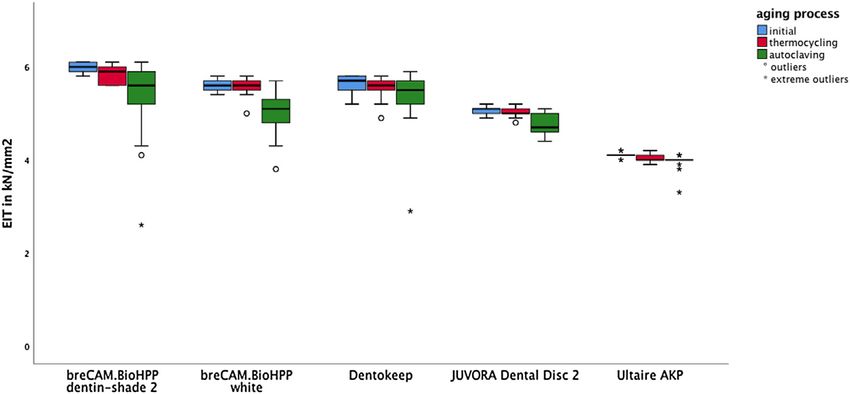
Um die Langzeitbeständigkeit und das Verhalten von Werkstoffen nach Alterungsprozessen vorher-

sagen zu können, sind das Temperaturwechselbad, die Dampfsterilisation und die Kausimulation

geeignete Methoden, um in vitro die klinische Situation adäquat nachzuahmen [13].

Allerdings ist die Datenlage über die mechanischen Eigenschaften und die Resistenz gegenüber

mechanischen und thermischen Belastungen von in der FLM Technologie hergestellten PEEK

Komponenten noch sehr rar, da bislang PEEK Werkstücke in der Zahnmedizin aus Granulat oder

Pellets gepresst sowie CAD/CAM-basierend aus industriell vorgefertigten Ronden gefräst worden

sind.

Aus diesem Grund setzt sich die vorliegende Arbeit mit dem 3D-Druck von PEEK in der FLM

Technologie auseinander und untersucht zusammenfassend folgende Aspekte:

    1. Vergleich der Martensparameter von 3D-gedruckten und gefrästen PAEK Materialien in

        Bezug auf Druckrichtung und künstlicher Alterung.

    2. Bruchlast von 3D-gedruckten PEEK Inlays im Vergleich zu gefrästen PEEK Inlays, direkten

        Komposit-Füllungen und nicht restaurierten Zähnen.

                                               3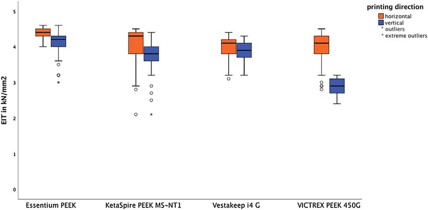
2. Publikationsliste

Prechtel A, Reymus M, Edelhoff D, Hickel R, Stawarczyk B. Comparison of various 3D printed and

milled PAEK materials: Effect of printing direction and artificial aging on Martens parameters. Dent

Mater 2020;36:197-209 (https://doi.org/10.1016/j.dental.2019.11.017)

IF 2018: 4.440

Prechtel A, Stawarczyk B, Hickel R, Edelhoff D, Reymus M. Fracture load of 3D printed PEEK

inlays compared with milled ones, direct resin composite fillings, and sound teeth. Clin Oral Investig

2020; [epub 27.01.2020] (https://doi.org/10.1007/s00784-020-03216-5)

IF 2018: 2.453

                                                  4
3. Eigene Arbeiten
Nachfolgend werden zwei Originalarbeiten in englischer Sprache vorgestellt und zusammengefasst.
3.1 Originalarbeit: Prechtel A, Reymus M, Edelhoff D, Hickel R, Stawarczyk B.
Comparison of various 3D printed and milled PAEK materials: Effect of printing
direction and artificial aging on Martens parameters. Dent Mater 2020;36:197-
209 (https://doi.org/10.1016/j.dental.2019.11.017) IF 2018: 4.440´
Zusammenfassung
Ziel: Das Ziel dieser Untersuchung war es, den Einfluss einer künstlichen Alterung auf die Martens-
parameter von verschiedenen 3D-gedruckten und gefrästen PAEK Werkstoffen zu ermitteln.
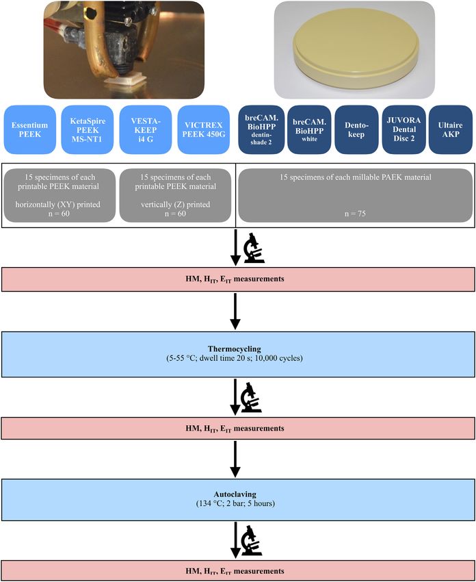
Material und Methode: Es wurden insgesamt 120 Prüfkörper aus vier unterschiedlichen PEEK
Materialien (Essentium PEEK (ESS), KetaSpire PEEK MS-NT1 (KET), VICTREX PEEK 450G
(VIC) und VESTAKEEP i4G (VES)) mittels FLM Technologie additiv hergestellt. Dabei wurden je
Material 15 Prüfkörper in horizontaler und vertikaler Druckrichtung gefertigt. Von den industriell
fabrizierten PAEK Ronden (breCAM.BioHPP (BHD/ BHW), Dentokeep (DEN), JUVORA Dental
Disc 2 (JUV) und Ultaire AKP (ULT)) wurden ebenfalls jeweils 15 Prüfkörper herausgefräst (n=75).
Anschließend wurden die Martenshärte (HM), die Eindringhärte (HIT) und der Eindringmodul (EIT)
vor und nach einer künstlichen Alterung durch ein Temperaturwechselbad (5-55 °C, 10.000
Thermozyklen) und einer Dampfsterilisation (134 °C, 2 bar) gemessen. Zusätzlich wurde jeweils die
Oberflächenbeschaffenheit der Prüfkörper auf Veränderungen durch diese Alterung licht-
mikroskopisch begutachtet.
Die ermittelten Daten wurden mittels Kolmogorov-Smirnov Test, einfaktorieller ANOVA mit an-
schließendem post-hoc Scheffé Test und partiellem Eta-Quadrat sowie mittels Kruskal-Wallis-,
Mann-Whitney-U-, Friedmann- und Wilcoxon-Test ausgewertet. Dabei wurde jeweils ein Wert von
pErgebnisse: Im Allgemeinen zeigten die gefrästen Prüfkörper höhere Martensparameter als die gedruckten Prüfkörper (p
d e n t a l m a t e r i a l s 3 6 ( 2 0 2 0 ) 197–209

                                             Available online at www.sciencedirect.com

                                                       ScienceDirect

                             journal homepage: www.intl.elsevierhealth.com/journals/dema

Comparison of various 3D printed and milled PAEK
materials: Effect of printing direction and artificial
aging on Martens parameters

Alexander Prechtel a,∗,1 , Marcel Reymus b,1 , Daniel Edelhoff a ,
Reinhard Hickel b , Bogna Stawarczyk a
aDepartment of Prosthetic Dentistry, LMU Munich, Goethestrasse 70, Munich, 80336, Germany
bDepartment of Conservative Dentistry and Periodontology, LMU Munich, Goethestrasse 70, Munich, 80336,
Germany

a r t i c l e      i n f o                  a b s t r a c t

Article history:                            Objectives. The aim of this study was to investigate the effect of artificial aging on the Martens
Accepted 15 November 2019                   parameters of different 3D printed and milled polyaryletherketon (PAEK) materials.
                                            Methods. In total 120 specimens of 4 different polyetheretherketon (PEEK) materials (Essen-
                                            tium PEEK, KetaSpire PEEK MS-NT1, VICTREX PEEK 450 G and VESTAKEEP i4 G) were
Keywords:                                   additively manufactured via fused layer manufacturing (FLM) in either horizontal or verti-
PAEK                                        cal directions (n = 15 per group). 75 specimens were milled out of prefabricated PAEK blanks
3D printing                                 from the materials breCAM.BioHPP, Dentokeep, JUVORA Dental Disc 2 and Ultaire AKP ( = 15
Additive manufacturing                      per group). Martens hardness (HM), indentation hardness (HIT ) and indentation modulus
Fused layer manufacturing (FLM)             (EIT ) were determined initially and longitudinally after thermocycling (5−55 ◦ C, 10,000x)
Martens parameters                          and autoclaving (134 ◦ C, 2 bar). In each case, the surface topography of the specimens was
Thermocycling/autoclaving                   examined for modifications using a light microscope.
                                              Data were analysed with Kolmogorov-Smirnov test, univariate ANOVA followed by
                                            post-hoc Scheffé test with partial eta squared (!p 2 ), Kruskal–Wallis-, Mann–Whitney-U-,
                                            Friedman- and Wilcoxon-Test. A value of p < 0.05 was considered as significant.
                                            Results. Milled specimens showed higher Martens parameters than printed ones (p < 0.001).
                                            Artificial aging had a negative effect on the measured parameters (p < 0.001). Horizon-
                                            tally printed specimens presented higher Martens parameters than vertically printed ones,
                                            regardless of material and aging process (p < 0.001). Essentium PEEK and breCAM.BioHPP
                                            showed the highest and VICTREX PEEK 450G as well as Ultaire AKP the lowest values of all
                                            investigated PAEK materials initially, after thermocycling and after autoclaving (p < 0.001).
                                            Microscopic examinations showed that artificial aging did not cause any major modifications
                                            of the materials.
                                            Significance. Additively manufactured PEEK materials showed lower Martens parameters
                                            than milled ones, whereas horizontally printed specimens presented higher values than
                                            vertically printed ones. Artificial aging had a negative effect on the Martens parameters, but
                                            not on the surface topography.
                                                © 2019 The Academy of Dental Materials. Published by Elsevier Inc. All rights reserved.

    ∗
   Corresponding author.
   E-mail address: Alexander.Prechtel@med.uni-muenchen.de (A. Prechtel).
    1
   Joint first authors.
https://doi.org/10.1016/j.dental.2019.11.017
0109-5641/© 2019 The Academy of Dental Materials. Published by Elsevier Inc. All rights reserved.

                                                                      7
198 d e n t a l m a t e r i a l s 3 6 ( 2 0 2 0 ) 197–209
PAEK polymers can be processed in a variety of ways.
1. Introduction Since 2011 CAD/CAM-supported milling of industrially pre-
fabricated blanks is available [17]. For processing PAEKs for
In dentistry, the possibility of using additive manufacturing
3D printing technology FLM is available, which was firstly
(AM) technologies for producing objects layer by layer has been
reported by Valentan in 2013 [18]. In this technique, the solid
used in a digital workflow with data acquisition, computer-
filament is heated at the nozzle to a semi-liquid state and
aided design (CAD) and computer-aided manufacturing (CAM)
then placed on the printer’s building platform or previously
since the late 1980s [1]. In recent years, the development
printed layers. The single layers are then fused together to
of new materials, printing techniques and machines has
the final component [6]. Due to the high crystalline melt tran-
increased rapidly, giving three-dimensional (3D) printing the
sition temperature (Tm = 343 ◦ C) of PEEK, a special 3D printer
potential to revolutionize traditional dentistry in clinical treat-
is required that can provide the high melt and ambient tem-
ment, research and education. Its indications extend from
peratures and keep the temperature of the nozzle, building
prosthodontics, oral and maxillofacial surgery to orthodon-
platform and chamber constant for a long time in a con-
tics, endodontics and periodontics [2]. The advantages of AM
trolled process. Previous literature about PEEK processed via
are very convincing, such as the fabrication of complex indi-
FLM was based mostly on custom-made printing machines. It
vidual geometries, on-demand production of small quantities,
was found by fourier transform infrared (FTIR) spectroscopy
a high economic efficiency due to a theoretical material yield
analyses and in-vitro cytotoxicity tests that the high temper-
of 100 %, accelerated and cost-effective innovation processes,
atures do not modify the molecular structure of PEEK and no
as well as high precision [3]. On the negative side, high process-
toxic substances were produced during the printing process,
and material costs, a complex workflow with presupposed
which is very important for medical use [19]. Generally, the
technical know-how, anisotropic behaviour as well as a time-
few existing studies have shown that the mechanical prop-
consuming postprocessing of the printed object have to be
erties of printed components out of PEEK via FLM depend on
mentioned. 3D printing is already successfully applied in var-
printing temperature, layer thickness, printing speed, extru-
ious medical and dental fields [4,5].
sion path, filling ratio, raster angle and printing direction
Several printing techniques are available for processing
[20–23].
polymers such as polyamide (PA), polycarbonate (PC) and
However, data on the mechanical properties of FLM man-
acrylonitrile-butadiene-styrene (ABS); namely: stereolithogra-
ufactured PEAK components for dental applications is still
phy (SLA), selective laser sintering (SLS), inkjet 3D printing
limited. The aim of this study was to examine the influence
(3DP) and fused layer manufacturing (FLM) [6]. The last one
of artificial aging on the hardness of PEEK materials man-
is suitable for thermoplastic elastomers (TPE) such as modern
ufactured with either a commercially available FLM printer
high-performance polymers from the group of polyarylether-
or different PAEK polymers milled from industrially pre-
keton (PAEK).
fabricated blanks.
Especially, the increasing demand of many patients
Hardness is an important parameter for the durability of
for biocompatible, metal-free and esthetic dentures makes
a material [24]. The Martens hardness test method is partic-
PAEK attractive as an alternative to conventional restora-
ularly suitable for polymer-based dental materials, in which
tive materials, where polyetheretherketon (PEEK) represents
the effects of elastic and plastic deformation are determined.
the best known and dominant member of the PAEK fam-
Furthermore, this method of measurement is independent of
ily.
the optical and subjective measurement of indentations of the
PAEKs are semi-crystalline thermoplastics in which aro-
indenter.
matics are linearly linked in different orders via ether and
The null hypothesis was that there were no differences in
ketone connections [7]. The amount of these functional
the Martens parameters between 3D printed and milled PAEK
groups determines the mechanical and thermal proper-
materials regardless artificial aging and printing direction.
ties. The synthesis is based on condensation polymerization
using electrophilic or nucleophilic substitution. Due to its
excellent biocompatibility [8,9] and its high mechanical prop-
erties, it has been used for many years in medicine for
spinal implants, femoral stems or trauma implants [7,10].
For dentistry, the chemical stability, X-ray translucency, bone-
like elastic modulus (3–4 GPa), tooth-like colour and a low 2. Materials and methods
plaque accumulation are very advantageous [7]. In contrast
to conventional dental methylmethacrylate-based polymers, A total number of 204 specimens (10 mm × 10 mm × 5 mm)
PAEKs are free of residual monomer, making them ideal were manufactured, embedded in acrylic resin (ScandiQuick
as an alternative material not only for patients with a A and B, ScanDia, Hagen, Germany, LOT No. 09201 and 09202)
high risk of allergies. So far, only one case of a chronic and polished with P500 for 30 s and with P1200 (SiC-Papier,
systemic allergy to PEEK has been reported in the litera- Struers, Ballerup, Denmark) for 15 s with an half-automatic
ture [11]. The application of PAEKs in dentistry has a wide polishing machine (Tegramin-20, Struers) under permanent
range. For example, they are used as frameworks for crowns water cooling. Finally, the specimens were cleaned in an ultra-
and bridges, dentures bases and clasps, partial crowns, sonic bath (L&R Transistor/ Ultrasonic T-14, L&R, Kearny, NJ,
implants, implant abutments and esthetic orthodontic wires USA) for 5 min in distilled water. The study design is depicted
[12–16]. in Fig. 1.
8d e n t a l m a t e r i a l s 3 6 ( 2 0 2 0 ) 197–209 199
Fig. 1 – Study design: hardness measurements and microscopic examinations initially and after artificial aging on printed
and milled specimens.
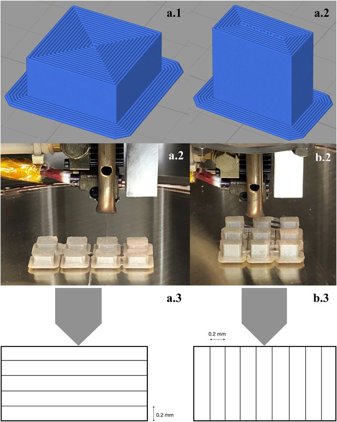
2.1. 3D printed PEEK specimens widths (0.30, 0.40 and 0.50 mm) on the Martens parameters
was investigated in order to subsequently determine the final
For each printable PEEK material (Essentium PEEK, KetaSpire printing parameters for the main prints. These were: printing
PEEK MS-NT1, VICTREX PEEK 450G, VESTAKEEP i4 G) (Table 1) speed 900 mm/min, layer height 0.2 mm and extrusion width
thirty specimens were manufactured as filament by FLM (fila- 0.4 mm. The specimens of the pilot and main prints were all
ment diameter: 1.75 mm) using the printer HTRD1.1 (KUMOVIS manufactured with 100 % interior fill.
GmbH, Munich, Germany). The technical specifications of the In order to evaluate the influence of the printing direction
printer are shown in Table 2. In this 3D printer, the extruder (layer orientation) on the Martens parameters, fifteen speci-
moves along the X-, Y- and Z-axes, while the building platform mens for each printable PEEK material were printed in either
remains in a fixed position. Before the printing process the fil- horizontal (XY) or vertical (Z) directions
ament was put into an oven (Heraeus RT 360, Heraeus Holding (Fig. 2). With the horizontally printed specimens, the layers
GmbH, Hanau, Germany) at 120 ◦ C for 12 h to extract moisture were oriented perpendicular to the measuring direction and
from the material. for the vertical ones, the layer orientation was parallel to the
Initially, pilot prints (P1-P9) were made, whereby the influ- penetration of the indenter pyramid.
ence of different printing speeds (600, 900 and 1200 mm/min), After the printing process all specimens were carefully
layer heights (0.10, 0.15, 0.20 and 0.30 mm) and extrusion removed with a cutter from the building platform immedi-
9200 d e n t a l m a t e r i a l s 3 6 ( 2 0 2 0 ) 197–209
Table 1 – Summery of production process, PAEK materials, abbreviations, compositions, manufacturer and LOT numbers.
Production PAEK material Abbreviation Composition Manufacturer LOT No.
process
Essentium PEEK ESS Polyetheretherketon, Essentium Inc., 1-80601
Printing
unfilled Pflugerville, USA
(horizontal and
KetaSpire® PEEK KET Polyetheretherketon, Solvay Specialty 1850009004
vertical direction)
MS-NT1 unfilled Polymers USA, L.L.C.,
Alpharetta GA, USA
VESTAKEEP® i4 G VES Polyetheretherketon, Evonik Industries “testing grade”
(exp. material) unfilled AG, Essen, Germany version
VICTREX® PEEK 450G VIC Polyetheretherketon, Victrex plc., 7082
unfilled Thornton Cleveleys,
UK
BHD Polyetheretherketon, bredent, 438245
breCAM.BioHPP® Senden,
filled with
Milling app. 30 % TiO2 , Germany
dentin-shade 2
BHW Polyetheretherketon, 406700
filled with
app. 20 % TiO2 , white
Dentokeep DEN Polyetheretherketon, Trading GmbH & Co. 11DK18001
filled with KG, Karlsruhe,
app. 20 % TiO2 Germany
JUVORATM Dental JUV Polyetheretherketon, JUVORA Ltd., WO000042IDML
Disc 2 unfilled Thornton Cleveleys,
UK
UltaireTM AKP ULT Aryl-Keton-Polymer, Solvay Dental 360TM , 1641125024032
unfilled Alpharetta GA, USA
2.4. Martens hardness (HM), indentation hardness
Table 2 – Technical specifications of HTRD1.1.
(HIT ) and indentation modulus (EIT )
Nozzle temperature 410 ◦ C
Nozzle diameter 0.4 mm
Heated building chamber 200 ◦ C
An universal hardness testing machine (ZHU 0.2/ Z2.5, Zwick
Heated building platform 250 ◦ C Roell, Ulm, Germany) was used to determine the Martens
Ventilation Heated laminar airflow parameters (HM in N/mm2 , HIT in N/mm2 and EIT in kN/mm2 )
Clean room filter system No initially and directly after the thermocycling and autoclaving
Slicing software Simplify3D® (version 4.1, process. The measurement of Martens parameters is based on
Cincinnati, OH, USA)
the principle of pressing an indenter into the surface of a spec-
imen and continuously measuring the force F (in N) and the
penetration depth h (in !m) during the loading and unloading
phase (DIN EN ISO 14577) [25].
During measurement, the diamond indenter pyramid
ately, cooled down at room temperature and measured 24 h (˛ = 136◦ ) of the testing machine was pressed vertically into
later. the surface of the specimen for 10 s with a load of 9.807 N. The
maximum penetration depth of the pyramid into the material
was 0.05 mm. The movement of the indenter represented the
2.2. Milled PAEK specimens
sum of elastic deformation of the surface together with the
plastic penetration depth [24]. HM, HIT and EIT were automat-
For each millable PAEK material (breCAM.BioHPP, Dentokeep,
ically calculated with the corresponding software (testXpert
JUVORATM Dental Disc 2, Solvay UltaireTM AKP) (Table 1)
V12.3 Master, Zwick Roell) using the following equations (DIN
fifteen specimens were milled out of pre-fabricated blocks
EN ISO 14577) [25]:
with a handpiece (KaVo EWL K9, KaVo Dental, Biberach/ Riß,
Germany). F F
HM = =
As (h) 26.43×h2
2.3. Hydrothermal aging process of specimens Fmax
HIT =
Ap
The specimens were thermocycled (Thermocycler THE 1100,
# ! "$ -1
SD Mechatronics, Feldkirchen-Westerham, Germany) between √
! " 1 1 − v2i !
5 and 55 ◦ C with a dwell time for 20 s for 10,000 cycles. Sub- EIT = 1 − v2s × − with Er = %
Er Ei 2C Ap
sequently, the hydrothermal aging was performed using an
autoclave for five hours at 134 ◦ C and 2 bar (Euroklav 29-S, with HM in N/mm2 , F (test force) in N, As (h) (surface area
MELAG Medizintechnik oHG, Berlin, Germany). of the indenter at distance h from the trip) in mm2 , h (inden-
10d e n t a l m a t e r i a l s 3 6 ( 2 0 2 0 ) 197–209 201
Fig. 2 – Sliced (1), printed (2) and measured (3) specimens in horizontal (a) and vertical direction (b). The arrow indicates the
penetration direction of the indenter pyramid.
tation depth under applied test force) in mm, HIT in N/mm2 , particular and the area below the unloading curve showed the
Fmax (maximum test force) in N, Ap (projected (cross-sectional) elastic re-deformation work [27].
area of contact between the indenter and the test piece deter-
mined from the force-displacement curve and a knowledge
of the area function of the indenter) in mm2 , EIT in kN/mm2 ,
Er (reduced modulus of the indentation contact) in N/mm2 , Ei
2.5. Surface topography analysis
(elastic modulus of the indenter) in N/mm2 , C (compliance of
the contact), vs (Poisson’s ratio of the test piece) = 0.35 [26] and
The surface topography of the specimens was analysed with a
vi (Poisson’s ratio of the indenter) = 0.3.
light microscope (Leica DM2700 M, Leica Microsystems GmbH,
Load-displacement curves (Fig. 3) indicated the penetration
Wetzlar, Germany) using magnifications of ×5 and ×20 with
depth of the indenter in relation to the test force and provide
the LAS X software (version 3.4.2, Leica Microsystems GmbH).
further information about the material behaviour. The area
Care was taken with a marker line and measured adjustment
between the loading and unloading curve indicated the pene-
of the stage from the microscope to ensure that the same point
tration work of the material, while the area below the loading
was always observed for each specimen after the aging process
curve represented the irreversible plastic deformation work in
in order to be able to make comparable statements.
11202 d e n t a l m a t e r i a l s 3 6 ( 2 0 2 0 ) 197–209
Fig. 3 – Load-displacement curves of BHD (a.I and c), ULT (a.II), horizontally printed ESS (a.III), vertically printed VIC (a.IV)
and vertically printed KET (b).
2.6. Statistical analysis direction) was also significant (HM: !p 2 = 0.294, p < 0.001; HIT :
!p 2 = 0.308, p < 0.001; EIT : !p 2 = 0.211, p < 0.001).
All statistical analyses were performed with the SPSS statistics For the milled specimens the highest impact was exerted
program (version 25.0.0.1, IBM, Armonk, NY, USA). Descrip- by material (HM: !p 2 = 0.817, p < 0.001; HIT : !p 2 = 0.834, p < 0.001;
tive statistics were computed. The presumption of normal EIT : !p 2 = 0.738, p < 0.001) followed by the aging process (HM:
distribution was tested using Kolmogorov-Smirnov test. The !p 2 = 0.256, p < 0.001; HIT : !p 2 = 0.208, p < 0.001; EIT : !p 2 = 0.201,
univariate ANOVA with partial eta squared (!p 2 ) was calcu- p < 0.001) and the binary combination between both param-
lated for an overall consideration of the data. To determine eters (HM: !p 2 = 0.122, p < 0.001; HIT : !p 2 = 0.128, p < 0.001; EIT :
significant differences between the various PAEK materials !p 2 = 0.064, p < 0.001).
and printing direction non-parametric Kruskal–Wallis- and In general, milled specimens showed higher values for
Mann–Whitney-U-Test were used. To evaluate the aging pro- the Martens parameters than printed ones (p < 0.001). Differ-
cess Friedman- and Wilcoxon-Test were calculated. A value of ences between the materials within one aging level (p < 0.001)
p < 0.05 was considered as significant. have been recorded. Furthermore, horizontally printed spec-
imens presented higher Martens parameters than vertical
ones, regardless of material or aging process (p < 0.001).
3. Results
Essentium PEEK (ESS) showed the highest and VICTREX
PEEK 450 G (VIC) the lowest values of all printable PEEK
The descriptive statistics are summarized in Tables 3 and 4.
materials initially, after thermocycling and after autoclaving
Data were analysed nonparametrically, because the
(p < 0.001), whereby VIC showed initially a comparable HM
Kolmogorov-Smirnov test showed that more than 5% of the
value with VESTAKEEP i4 G (VES) (p = 0.290) and KetaSpire
tested groups (47/117) deviated from the normal distribution.
PEEK MS-NT1 (KET) (p = 0.104). For HIT initially and after ther-
mocycling, VIC was with KET (p = 0.228 and p = 0.143) and
3.1. Results of the pilot prints
VES (p = 0.340 and p = 0.301) in the same value range. KET
and VES showed comparable EIT values initially (p = 0.405),
Analysing printing speed, specimens printed at 900 mm/min
HM (p = 0.403) and EIT (p = 0.603) after thermocycling and HM
and 1200 mm/min showed the highest HM (p = 0.290) and
(p = 0.673), HIT (p = 0.853) and EIT (p = 0.246) after autoclaving
EIT values (p = 0.170). For HIT all three examined printing
(Fig. 3).
speeds were within the same value range (p = 0.070). With
For the milled specimens, breCAM.BioHPP with app. 30 %
regard to layer height, no differences could be found in
TiO2 (BHD) presented initially, after thermocycling and after
the Martens parameters between the various settings (HM:
autoclaving the highest Martens parameters (p < 0.001). Ultaire
p = 0.626; HIT : p = 0.547; EIT : p = 0.562). For extrusion width,
AKP (ULT) showed initially and after the hydrothermal aging
specimens printed with 0.4 mm and 0.5 mm showed the high-
the lowest Martens parameters of all tested millable PAEK
est HM (p = 0.820), EIT (p = 0.796) and HIT values (p = 0.616).
materials (p < 0.001) (Fig. 4).
Finally, differences in the Martens parameters between hor-
Generally, there are significant differences in the Martens
izontally and vertically printed specimens were found (HM:
parameters due to the aging process, with the highest values
p = 0.001; HIT : p = 0.002; EIT : p < 0.001).
being reached initially (p < 0.001). Dentokeep (DEN), horizon-
tally printed KET, vertically printed VES and horizontally as
3.2. Results of the printed and milled PAEK specimens
well as vertically printed VIC showed within their group
comparable Martens parameters independently of the aging
Regarding printed specimens the highest impact on HM
process. Horizontally printed ESS and VES as well as vertically
and EIT was exerted by material (HM: !p 2 = 0.387, p < 0.001;
printed ESS and KET presented initially higher EIT than after
EIT : !p 2 = 0.405, p < 0.001) followed by the printing direc-
autoclaving (p = 0.008–0.046). Specimens printed vertically out
tion (HM: !p 2 = 0.368, p < 0.001; EIT : !p 2 = 0.283, p < 0.001) and
of ESS showed after the hydrothermal aging significant lower
the aging process (HM: !p 2 = 0.020, p = 0.036; EIT : !p 2 = 0.097,
HM and HIT values than initially.
p < 0.001). For HIT , the printing direction had the highest
BHD and breCAM.BioHPP with app. 20 % TiO2 (BHW) pre-
impact (!p 2 = 0.374, p < 0.001) followed by material (!p 2 = 0.361,
sented initially higher Martens parameters than after the
p < 0.001), while the aging process did not show an effect
aging process (p < 0.001). For JUVORA Dental Disc 2 (JUV)
(p = 0.387). The binary combination (material and printing
12Table 3 – Descriptive statistics for Martens parameters of the pilot prints according to the printing direction, printing speed, layer height, extrusion width and printing
time.
Printing Printing Layer Extrusion Printing HM [N/mm2 ] HIT [N/mm2 ] EIT [kN/mm2 ]
Specimen height
direction speed width time
[mm/min] [mm] [mm] [min] Mean ± SD 95 % CI Min/Median/ Mean ± SD 95 % CI Min/Median/ Mean ± SD 95 % CI Min/Median/
Max Max Max
P1 horizontal 900 0.20 0.40 22 153 ± 21.9Bb 129; 177 114/156/179 230 ± 39.4b 187; 272 159/235/275 3.72 ± 0.256Bb 3.43; 3.99 3.3/3.7/4.1
P2 horizontal 1200 0.20 0.40 9 131 ± 29.6ABb 99; 163 87/134/171 196 ± 49.7b 143; 249 123/198/266 3.20 ± 0.540ABb 2.62; 3.77 2.4/3.4/3.8
P3 horizontal 600 0.20 0.40 33 98.5 ± 49.1Ab 46; 150 40/92/163 145 ± 82.4b 58.1; 232 49/133/251 2.73 ± 0.638Ab 2.05; 3.41 2.0/2.5/3.7
13
P4 horizontal 900 0.20 0.30 22 93.8 ± 31.5Ba 59; 127 66/87/153 140 ± 56.4a 80.2; 199 94/123/248 2.38 ± 0.504Ba 1.84; 2.92 1.9/2.3/3.2
P5 horizontal 900 0.20 0.50 22 142 ± 34.7Bb 104; 178 98/146/185 212 ± 56.6b 151; 272 142/218/281 3.45 ± 0.663Bb 2.74; 4.15 2.6/3.6/4.4
P6 horizontal 900 0.30 0.40 13 157 ± 25.51 Bb 129; 184 114/170/176 237 ± 43.0b 190; 283 161/257/272 3.73 ± 0.472Bb 3.22; 4.23 3.1/3.9/4.2
P7 horizontal 900 0.15 0.40 25 148 ± 27.1Bb 118; 177 102/148/180 222 ± 44.9b 174; 270 146/221/276 3.60 ± 0.566Bb 2.99; 4.20 2.7/3.7/4.1
P8 horizontal 900 0.10 0.40 41 135 ± 42.4Bb 89; 180 80/149/178 196 ± 70.5b 120; 271 105/220/271 3.62 ± 0.611Bb 2.96; 4.26 2.9/3.7/4.3
P9 vertical 900 0.20 0.40 43 181 ± 8.66Bb 170; 190 170/183/190 270 ± 16.1b 252; 287 250/273/287 4.42 ± 0.117Bb 4.28; 4.54 4.2/4.5/4.5
d e n t a l m a t e r i a l s 3 6 ( 2 0 2 0 ) 197–209
A,B
Indicate significant differences among the printing speed.
a,b
Indicate significant differences among the extrusion width.
1
Indicates group without normaldistribution.
203Table 4 – Descriptive statistics for Martens parameters according to the production process, PAEK material and aging process.
204
Production PAEK Aging HM [N/mm2 ] HIT [N/mm2 ] EIT [kN/mm2 ]
process material process
(Printing MW ± SD 95 % CI Min/Median/ MW ± SD 95 % CI Min/Median/ MW ± SD 95 % CI Min/Median/
direction) Max Max Max
Initial 181; 187 179/185/191 272; 281 267/277/287 4.41; 4.50 4.4/4.5/4.6
Printing
185 ± 3.51B 277 ± 6.05B 4.46 ± 0.0631 ,Cb
Thermocycling 175; 183 165/179/188 263; 275 245/ 271/282 4.23; 4.39 4.1/4.3/4.5
(horizontal)
179 ± 5.87 C 270 ± 9.69B 4.31 ± 0.125Ca
Autoclaving 181 ± 5.46C 177; 185 171/184/188 273 ± 9.16C 268; 278 252/276/282 4.34 ± 0.1401 ,Ca 4.27; 4.42 4.0/4.4/4.5
ESS
Initial 169; 187 129/182/190 255; 285 180/277/286 4,11; 4,38 3.7/4.3/4.6
Printing
179 ± 14.51 ,Bb 271 ± 25.91 ,Bb 4.25 ± 0.2261 ,Cb
Thermocycling 150; 182 89/175/189 222; 275 119/267/284 3.84; 4.31 3.0/4.2/4.5
(vertical)
166 ± 26.81 ,Ca 249 ± 45.81 ,Ba 4.08 ± 0.402Cab
Autoclaving 169 ± 10.0Ca 161; 175 150/168/183 262 ± 15.4Ca 252; 271 225/264/279 3.86 ± 0.4121 ,Ca 3.62; 4.09 3.2/4.0/4.3
Initial 151; 189 74/182/189 226; 287 105/275/285 3.69; 4.47 2.1/4.3/4.5
Printing
171 ± 33.21 ,A 257 ± 52.61 ,A 4.09 ± 0.6851 ,B
Thermocycling 166; 186 137/181/192 255; 280 216/273/291 3.86; 4.42 3.0/4.3/4.5
(horizontal)
177 ± 16.01 ,B 268 ± 20.41 ,A 4.14 ± 0.4881 ,B
Autoclaving 164 ± 20.9B 151; 176 114/159/187 250 ± 31.3B 231; 268 171/255/283 3.81 ± 0.553B 3.49; 4.12 2.8/3.9/4.5
KET
Initial 139; 160 115/147/178 201; 239 160/215/269 3.69; 3.96 3.3/3.8/4.3
Printing
150 ± 17.8A 220 ± 32.5A 3.83 ± 0.226Bb
Thermocycling 140; 166 107/155/184 204; 246 153/227/281 3.63; 4.09 2.9/3.9/4.4
(vertical)
153 ± 21.4B 226 ± 35.6A 3.87 ± 0.392Bb
Autoclaving 144 ± 28.4B 127; 160 86/142/177 217 ± 46.9B 190; 244 120/208/273 3.45 ± 0.5761 ,Ba 3.12; 3.78 2.1/3.6/4.1
Initial 160; 174 141/171/180 240; 262 204/259/270 3.93; 4.21 3.7/4.2/4.4
Printing
168 ± 10.4A 252 ± 17.5A 4.07 ± 0.2311 ,Bb
Thermocycling 164; 178 142/176/180 247; 268 208/265/271 3.96; 4.27 3.6/4.2/4.4
(horizontal)
172 ± 10.71 ,A 258 ± 17.11 ,A 4.12 ± 0.2651 ,Bb
Autoclaving 161 ± 16.5B 151; 171 113/169/179 246 ± 26.01 ,B 231; 261 161/254/268 3.78 ± 0.4201 ,Ba 3.53; 4.02 3.1/4.0/4.3
VES
Initial 141; 164 113/157/176 205; 244 157/235/264 3.70; 4.02 3.3/3.9/4.3
Printing
153 ± 19.1A 225 ± 33.2A 3.87 ± 0.269B
Thermocycling 150; 169 130/165/176 221; 251 183/246/266 3.84; 4.10 3.6/4.0/4.3
(vertical)
160 ± 14.7A 237 ± 26.0A 3.97 ± 0.212B
Autoclaving 156 ± 13.0B 148; 164 133/158/176 234 ± 22.9B 220; 247 188/234/265 3.80 ± 0.254B 3.65; 3.95 3.2/3.8/4.2
Initial 163; 187 122/182/190 247; 287 175/279/291 3.86; 4.30 3.2/4.2/4.5
Printing
176 ± 20.01 ,A 268 ± 33.81 ,A 4.01 ± 0.378A
14
Thermocycling 165; 186 129/181/189 253; 285 190/281/288 3.85; 4.25 3.3/4.2/4.4
(horizontal)
176 ± 16.61 ,A 270 ± 27.21 ,A 4.05 ± 0.3461 ,A
Autoclaving 159 ± 32.8A 140; 178 101/171/196 244 ± 54.7A 212; 275 141/266/314 3.67 ± 0.610A 3.32; 4.02 2.8/3.8/4.3
VIC
Initial 94.1; 110 78/101/127 129; 157 105/143/189 2.79; 3.01 2.6/2.9/3.2
Printing
102 ± 13.8A 144 ± 23.6A 2.91 ± 0.183A
Thermocycling 97.0; 112 77/103/131 135; 162 103/143/199 2.80; 2.99 2.6/2.9/3.1
(vertical)
104 ± 13.1A 149 ± 23.1A 2.90 ± 0.156A
Autoclaving 108 ± 13.4A 99; 115 90/105/132 156 ± 23.7A 142; 170 126/152/203 2.83 ± 0.231A 2.68; 2.96 2.4/2.8/3.2
Initial 227 ± 3.58Fe 224; 230 221/227/233 329 ± 5.85Fe 324; 332 318/329/338 5.98 ± 0.1081 ,Ge 5.91; 6.05 5.8/6.0/6.1
BHD Thermocycling 216; 227 204/223/231 313; 330 287/326/335 5.72; 5.95 5.6/5.9/6.1
d e n t a l m a t e r i a l s 3 6 ( 2 0 2 0 ) 197–209
222 ± 7.73Gd 322 ± 13.01 ,Ed 5.84 ± 0.184Gd
Autoclaving 205 ± 18.2Gc 194; 216 155/208/224 303 ± 12.1Ec 296; 311 276/302/321 5.29 ± 0.9441 ,Gc 4.77; 5.81 2.6/5.6/6.1
Initial 220 ± 3.31Ee 216; 222 215/220/228 322 ± 5.01Ed 318; 325 315/321/335 5.59 ± 0.110Fe 5.52; 5.66 5.4/5.6/5.8
BHW Thermocycling 219 ± 5.84Fd 214; 223 205/219/227 322 ± 7.72Ee 316; 327 307/322/332 5.56 ± 0.196Fd 5.44; 5.67 5.0/5.6/5.8
Autoclaving 201 ± 12.7Ec 192; 208 172/203/220 297 ± 14.6Ec 287; 306 268/298/321 5.00 ± 0.529Fc 4.69; 5.30 3.8/5.1/5.7
Initial 217 ± 10.81 ,E 210; 224 199/222/228 317 ± 18.61 ,E 305; 327 282/324/336 5.61 ± 0.210F 5.48; 5.74 5.2/5.7/5.8
Milling DEN Thermocycling 217 ± 11.21 ,F 209; 223 190/222/229 317 ± 19.21 ,E 305; 328 277/325/337 5.57 ± 0.2441 ,F 5.42; 5.71 4.9/5.6/5.8
Autoclaving 212 ± 13.61 ,G 203; 220 169/212/228 314 ± 8.22F 308; 319 301/311/332 5.31 ± 0.7351 ,G 4.89; 5.73 2.9/5.5/5.9
Initial 217 ± 5.96Ed 212; 220 204/217/225 330 ± 11.81 ,F 322; 337 304/332/344 5.06 ± 0.0741 ,Ed 5.00; 5.11 4.9/5.1/5.2
JUV Thermocycling 215 ± 7.001 ,Ed 209; 219 202/217/223 327 ± 13.71 ,F 318; 328 301/333/342 5.01 ± 0.0991 ,Ed 4.94; 5.07 4.8/5.0/5.2
Autoclaving 208 ± 8.48Fc 202; 213 188/210/222 320 ± 16.01 ,G 310; 329 285/322/360 4.77 ± 0.215Ec 4.64; 4.90 4.4/4.7/5.1
Initial 171 ± 3.681 ,Dd 167; 174 160/172/175 257 ± 7.371 ,D 252; 262 235/259/264 4.10 ± 0.0541 ,Dd 4.06; 4.14 4.0/4.1/4.2
ULT Thermocycling 168 ± 4.73Dc 164; 171 156/169/176 253 ± 9.24 D 247; 259 232/254/267 4.05 ± 0.0741 ,Dcd 3.99; 4.09 3.9/4.0/4.2
Autoclaving 166 ± 4.17Dc 162; 169 156/167/171 251 ± 4.56D 247; 254 239/251/258 3.95 ± 0.1921 ,Dc 3.83; 4.06 3.3/4.0/4.1
A−G
Indicate significant differences among all tested materials within one Martens parameter and one aging process.
a−f
Indicate significant differences among the aging process within one Martens parameter and one material.
1
Indicates groups without normal distribution.d e n t a l m a t e r i a l s 3 6 ( 2 0 2 0 ) 197–209 205
Fig. 4 – Boxplot of EIT of the printed PEEK materials in relation to the printing direction regardless of the aging process.
and ULT, the values for HM (p = 0.008 and p = 0.002) and EIT In general, the Martens hardness test method is very well
(p = 0.001 and p = 0.003) are initially higher than after auto- suited to investigate the elastic and plastic deformation of
claving, whereas for JUV no difference between the initial and polymer-based materials like PAEK. The effects of morpholog-
aged values (HM: p = 0.509; EIT : p = 0.131) and for ULT no differ- ical surface degradations on the mechanical properties caused
ence between after thermocycling and after autoclaving (HM: by artificial aging can also be efficiently determined with this
p = 0.147; EIT : p = 0.058) was observed. test method [28]. HM is different from HIT only in the definition
Considering the load-displacement curves the loading and of the surface and indentation depth, so that there is a close
unloading curve of BHD had the steepest gradients and the relationship between both parameters [29]. HIT examines the
smallest area within the graph compared to the other mate- plastic behaviour of the material, while EIT describes the elas-
rials, which means that less penetration work has been tic performance and is comparable with the Young’s modulus
performed, which in turn indicated higher Martens param- [25].
eters (Fig. 5a.I). With the vertically printed VIC, due to the flat Pilot prints were performed to determine suitable param-
gradient and the large area within the graph, a lot of pene- eters for printing speed, layer height and extrusion width for
tration work was done so that the Martens parameters were the main prints. Regarding printing speed, 900 mm/min and
lowest (Fig. 5a.IV). 1200 mm/min showed comparable HM and EIT values, but due
The load-displacements curves of vertically printed KET to a subjectively higher printing quality of the specimens, the
(Fig. 5b) impressed with many slightly different curves, while main prints were set to 900 mm/min. With the layer height
the single curves of the specimens milled out of BHD over- no differences were found between the various settings on
lapped and were nearly uniform (Fig. 5c). the Martens parameters. Consequently a good compromise
between printing quality and printing time was found for
0.2 mm. The extrusion width was adjusted to 0.4 mm since
3.3. Surface topography analysis it was the same size as the nozzle.
The differences observed between the printed and milled
It could be observed microscopically that the hydrothermal PAEK materials need to be highlighted. Milled specimens
aging did not cause any major modifications in all investigated showed higher Martens parameters than printed ones. This
PAEK materials. No cracks, fractures, voids and dimension fact might be explained by the standardized conditions of
changes could be detected, which occurred in the process of manufacturing by which a controlled crystallization process
artificial aging (Fig. 6). of the thermoplastic material can take place. With the printed
The printed specimens impressed with a high amount specimens, the filament was melted in the extruder and sub-
of artefacts such as not seamlessly placed extrusion paths, jected to a more or less controlled crystallization after the
voids and air inclusions, which were already initially present printing process, which can be influenced by many factors.
directly after the printing process (Fig. 7). One important factor is temperature management and
cooling procedures. In the present investigation, the printed
specimens were all removed from the building platform
4. Discussion immediately after the end of the printing process and cooled
down slowly at room temperature. This raises the question of
In this in-vitro investigation the effect of artificial aging on how the mechanical properties will behave if the component
the Martens parameters to different 3D printed and milled remained in the heated building chamber for an extended
PAEK materials was evaluated. Based on the results, the null period of time or quickly cold down abruptly. As PAEK mate-
hypotheses were rejected because differences between the rials are polymers with a low degree of crystallization, their
printed and milled materials were found, the printing direc- mechanical properties dependent on crystallinity [30]. It is
tion had a major influence and the aging process showed a to be expected that components will have better mechani-
negative effect on the Martens parameters. cal properties during post heat treatment, since the material
15206 d e n t a l m a t e r i a l s 3 6 ( 2 0 2 0 ) 197–209
Fig. 5 – Boxplots of EIT of the milled PAEK materials in relation to the aging process.
Fig. 6 – Microscope images (×20) with indentation of milled specimen out of BHD (a) and vertically printed ESS (b) initially
(1), after thermocycling (2) and after autoclaving (3).
can crystallize even further after the printing process and cold Unfortunately, the manufacturers do not provide much infor-
crystallization can be prevented [23]. If cooling is too fast a mation about the materials’ compositions, except that both
lower degree of crystallization and cracks are possible due to a materials have no integrated fillers. VIC is a material devel-
strong temperature change [31]. However, Valentan et al. have oped and optimized mainly for traditional injection molding.
found that tensile strength decreases if the component is left The experience gained a weaker adhesion between the single
at a high temperature in the building chamber for 12 h. Con- layers, which might explain why vertically printed VIC showed
sequently, it should be removed from the printer immediately the lowest values.
after the end of the printing process in order to achieve the best In general, horizontally printed specimens showed higher
mechanical properties through slow cooling as performed in values than vertical ones regardless of material and aging pro-
this study [18]. cess. In case of the vertically printed specimens, the intender
A further reason for the lower values of the printed spec- pyramid was pressed into the surface parallel to the layers, so
imens might be due to the artefacts such as voids and air that measurements were also made randomly at exactly the
inclusions within the printed specimen, which weakened the junction between two layers. Minimal tensile stresses were
components mechanically. These artefacts are an indication generated, which resulted in separation and sliding of two
of the presence of moisture in the filament [18]. The filament adjacent layers [32]. With the horizontal specimens, however,
did not retain its dried state during the long printing process. the pyramid penetrated into the material perpendicular to
It can be expected that it regained moisture from the ambient the layers, so that due to the small size of the pyramid only
air. Therefore, a printer with a sealed chamber for the filament within one layer was measured and no tensile stresses were
spool would be necessary to maintain a dried state from the induced. The cohesive bonding within the same layer is also
oven during the printing process. higher than the adhesive bonding between superimposed lay-
ESS showed the highest Martens parameters regardless of ers [33]. Rinaldi et al. observed in tensile tests that specimens
the aging process and printing direction, while VIC presented printed in XY direction with 100% infill had better mechanical
the lowest values. It is difficult to find an explanation for this.
16d e n t a l m a t e r i a l s 3 6 ( 2 0 2 0 ) 197–209 207
Fig. 7 – Microscope images (×5) of printed specimens with extrusion paths that were not seamlessly placed against each
other (a), voids (b), wavy rim (c) and air inclusions between the layers (d).
properties than specimens printed in Z direction which is in no further information about the chemical composition and
accordance to our study [23]. exact filler content is available from the manufacturer.
The load-displacement curves of the printed materials When comparing Martens parameters with other dental
impressed by a high variance of the curves, which indicated CAD/CAM restorative materials, ceramics have by far the high-
divergent penetration work and Martens parameters between est and PMMA-based composite materials the lowest values
the single specimens of the same material. An explanation [27]. The investigated PAEK materials of the present study
might be that, although exactly the same printing parameters showed slightly better values than PMMA-based composite
were set before each printing process, there were minimal dif- materials.
ferent conditions for each print, such as room temperature, In dentistry, it is very important to use long-term restora-
humidity, manually set Z-height of the extruder and some- tive materials with a high clinical performance, as they are
times a replacement of the extruder or the glass plate. always exposed to a humid environment and dynamic tem-
In order to compare the Martens parameters between all perature changes when taking food, liquids and breathing. For
printable PEEK materials, each material was printed with this reason, thermocycling and autoclaving were used in the
exactly the same printing parameters. However, it would present investigation, aiming to imitate artificial aging of the
probably be necessary to find out the individual printing specimens. Thermocycling is often used in in-vitro studies,
parameters for each material in order to achieve the best pro- but there is no standardized protocol for number of cycles,
cessing conditions and mechanical properties. dwell time and temperatures [36]. For this study 10,000 cycles
For the milled specimens, BHD showed the highest Martens were chosen, which corresponds to one year in-vivo situation,
parameters independently of the aging process. This mate- and temperatures of 5−55 ◦ C, which are closest to the clinical
rial is filled with approximately 30 % titanium dioxide (TiO2 ), situation. Autoclaving was performed at 134 ◦ C, 2 bar and 5 h,
which might explain these results. By adding TiO2 , aluminium which represents 15–20 years in-vivo situation [37].
trioxide (Al2 O3 ), silicium dioxide (SiO2 ) or carbon fibers, PAEK Generally, temperature changes and thermal stresses lead
materials can be reinforced, which increases their mechanical to contraction and expansion in solid materials [36]. However,
properties [34,35]. BHW and DEN only contain approximately no cracks, fractures, voids and dimension changes could be
20 % TiO2 which might negatively have influenced the Martens observed under the light microscope. Further examinations
parameters. However, esthetic properties usually suffer as a using scanning electron microscopy are necessary to be able
result of the additives, so that not all PAEK compounds can to show morphological changes caused by the aging process
be used for aesthetic dental restorations in spite of better more precisely and to explain why the materials presented
mechanical performance. ULT showed the lowest Martens lower Martens parameter after the hydrothermal aging.
parameters. This might be explained by the fact that this The aging process in this investigation has shown that hor-
material is an unfilled aryl ketone polymer; but otherwise izontally printed ESS and VES, vertically printed ESS and KET,
17208 d e n t a l m a t e r i a l s 3 6 ( 2 0 2 0 ) 197–209
BHD, BHW, JUV and ULT were quite vulnerable to aging pro- [3] Ngo TD, Kashani A, Imbalzano G, Nguyen KTQ, Hui D.
cesses, as illustrated by a decrease in Martens parameters. Due Additive manufacturing (3D printing): a review of materials,
to possible microcracks caused by thermal stresses, moisture methods, applications and challenges. Compos B Eng
2018;143:172–96.
could be absorbed into the materials at the high temperature
[4] Liaw C-Y, Guvendiren M. Current and emerging applications
of the autoclave, so the mechanics suffers [38]. Most interest- of 3D printing in medicine. Biofabrication 2017;9:024102.
ingly, the printable materials seemed to be more resistant to [5] Tack P, Victor J, Gemmel P, Annemans L. 3D-printing
hydrothermal influences than milled ones, which is illustrated techniques in a medical setting: a systematic literature
by a low !p 2 . It can be speculated that the moisture absorption review. Biomed Eng Online 2016;15:115.
capacity of PEEK filaments is lower than that of PEEK blanks, [6] Wang X, Jiang M, Zhou Z, Gou J, Hui D. 3D printing of
but this cannot be verified due to a lack of information from polymer matrix composites: a review and prospective.
Compos B Eng 2017;110:442–58.
the manufacturers. In comparison to other materials such as
[7] Kurtz SM, Devine JN. PEEK biomaterials in trauma,
hybrid materials, nanohybrid composites and PMMA-based orthopedic, and spinal implants. Biomaterials
materials, PEEK has the lowest water absorption [39]. 2007;28:4845–69.
For future research, thermodynamic and scanning electron [8] Katzer A, Marquardt H, Westendorf J, Wening JV, von
microscopy investigations of the PEEK filaments are required, Foerster G. Polyetheretherketone — cytotoxicity and
which can explain the different mechanical behaviour. In mutagenicity in vitro. Biomaterials 2002;23:1749–59.
[9] Poulsson AH, Eglin D, Zeiter S, Camenisch K, Sprecher C,
addition, the used FLM printer and most of the PEEK filaments
Agarwal Y, et al. Osseointegration of machined, injection
have to be classified according to the Medical Devices Law in
moulded and oxygen plasma modified PEEK implants in a
order to be able to use printed components in dentistry and to sheep model. Biomaterials 2014;35:3717–28.
carry out in-vivo studies. [10] Toth JM, Wang M, Estes BT, Scifert JL, Seim HB, Turner AS.
Polyetheretherketone as a biomaterial for spinal
applications. Biomaterials 2006;27:324–34.
5. Conclusions [11] Maldonado-Naranjo AL, Healy AT, Kalfas IH.
Polyetheretherketone (PEEK) intervertebral cage as a cause of
Within the limitations of this in-vitro study, it can be summa- chronic systemic allergy: a case report. Spine J 2015;15:e1–3.
rized that: [12] Zoidis P, Bakiri E, Polyzois G. Using modified
polyetheretherketone (PEEK) as an alternative material for
endocrown restorations: a short-term clinical report. J
• PEEK specimens printed via FLM showed lower Martens
Prosthet Dent 2017;117:335–9.
parameters than milled ones, whereby printed ESS and [13] Tekin S, Cangül S, Adıgüzel Ö, Deger˘ Y. Areas for use of PEEK
milled BHD showed the highest values within their groups, material in dentistry. Int Dent Res 2018;8(2):84–92.
independently of artificial aging. [14] Park C, Jun DJ, Park SW, Lim HP. Use of polyaryletherketone
• The printing direction showed an influence on the Martens (PAEK) based polymer for implant-supported telescopic
parameters, whereas horizontally printed specimens had overdenture: a case report. J Adv Prosthodont 2017;9:74–6.
[15] Ali MZ, Baker S, Martin N. Traditional CoCr versus milled
higher values than the vertical ones.
PEEK framework removable partial dentures–pilot
• PAEK compounds with TiO2 resulted in higher Martens randomised crossover controlled trial; interim findings.
parameters than unfilled materials. ConsEuro 2015. BM09 London.
• The hydrothermal aging process showed a negative impact [16] Schwitalla A, Müller WD. PEEK dental implants: a review of
on the Martens parameters especially for the milled spec- the literature. J Oral Implantol 2013;39:743–9.
imens; the printed specimens were more resistant to [17] Stawarczyk B, Eichberger M, Uhrenbacher J, Wimmer T,
Edelhoff D, Schmidlin PR. Three-unit reinforced
hydrothermal stresses.
polyetheretherketone composite FDPs: influence of
• Additive manufacturing of PEEK for dental applications
fabrication method on load-bearing capacity and failure
seems promising, but still needs further investigation types. Dent Mater J 2015;34:7–12.
to understand material and process influences better. [18] Valentan B, Kadivnik Z, Brajlih T, Anderson A, Igor D.
Filament material filled with TiO2 as well as application- Processing poly(ether etherketone) on a 3d printer for
oriented testing for specific use-cases should be looked at thermoplastic modelling. Mater Tehnol 2013;47:715–21.
more closely in future. [19] Zhao F, Li D, Jin Z. Preliminary investigation of
poly-ether-Ether-Ketone based on fused deposition
modeling for medical applications. Materials 2018;11.
Acknowledgements [20] Deng X, Zeng Z, Peng B, Yan S, Ke W. Mechanical properties
optimization of poly-ether-Ether-Ketone via fused
deposition modeling. Materials 2018;11.
The authors would like to thank KUMOVIS for providing the
[21] Yang C, Tian X, Li D, Cao Y, Zhao F, Shi C. Influence of
3D printer HTRD1.1 and the PEEK filaments. thermal processing conditions in 3D printing on the
crystallinity and mechanical properties of PEEK material. J
references Mater Process Technol 2017;248:1–7.
[22] Wu W, Geng P, Li G, Zhao D, Zhang H, Zhao J. Influence of
layer thickness and raster angle on the mechanical
properties of 3D-Printed PEEK and a comparative mechanical
[1] van Noort R. The future of dental devices is digital. Dent study between PEEK and ABS. Materials 2015;8:5834–46.
Mater 2012;28:3–12. [23] Rinaldi M, Ghidini T, Cecchini F, Brandao A, Nanni F. Additive
[2] Oberoi G, Nitsch S, Edelmayer M, Janjić K, Müller AS, Agis H. layer manufacturing of poly (ether ether ketone) via FDM.
3D printing — encompassing the facets of dentistry. Front Compos B Eng 2018;145:162–72.
Bioeng Biotechnol 2018:6.
18Sie können auch lesen