Betriebs- und Montageanleitung für Hydraulische Seilaufhängung / Instruction and Operating Manual for Hydraulic Rope-Suspension "Balance"
←
→
Transkription von Seiteninhalten
Wenn Ihr Browser die Seite nicht korrekt rendert, bitte, lesen Sie den Inhalt der Seite unten
Betriebs- und Montageanleitung für
Hydraulische Seilaufhängung / Instruction
and Operating Manual for Hydraulic Rope-
               Suspension
                “Balance”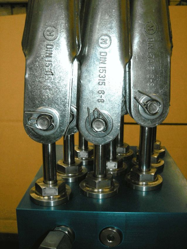
Beschreibung/Inbetriebnahme/Wartung                                      AS-GB-002/...
                                        Descrition/Installation/Maintenance                                      “balance”

0        Allgemeine Hinweise / General Information
         0.1     Allgemein / General
         Überprüfen Sie vor der Inbetriebnahm e den Zustand des Gerätes sowie des m itgelieferten Zubehörs. Lesen Sie vor
         der Inbetriebnahm e des Gerätes die Bedienungsanleitung.
         Falsche Handhabung bzw. die Nichteinhaltung von Gebrauchshinweisen oder technischen Angaben kann zu Sach-
         und / oder Personenschäden führen.
         Prior to initial operation please examine the condition of the unit and the fittings supplied. Please read the instructions
         before installing the device. Improper handling and/or non-compliance with the operating instructions or technical
         instructions may lead to material damage or personal injury

         0.2     Sicherheitshinweise Elektrik / Safety Instructions Electricity
         Verletzungsgefahr durch elektrischen Strom !
         Arbeiten an elektrischen Kom ponenten sind nur von einer Elektrofachkraft oder unter Anleitung und Aufsicht einer
         solchen durchzuführen.
         Die elektrischen Ausrüstungen sind regelm äßig von einer Elektrofachkraft zu prüfen. Alle Mängel, wie lose
         Verbindungen bzw. defekte oder beschädigte Kabel sind sofort zu beseitigen!
         Risk of injury from electric current!
         W ork on electrical components is only to be conducted by a qualified electrician or under the supervision of a
         qualified electrician. Electrical equipment should be inspected regularly by a qualified electrician. All defects, such as
         loose connections, faulty or damaged cables must be repaired immediately!

         0.3     Sicherheitshinweise Hydraulik / Safety Instructions - Hydraulics
         Mit Arbeiten an hydraulischen Einrichtungen dürfen nur Personen beauftragt werden, die über spezielle Kenntnisse
         und Erfahrungen in der Hydraulik verfügen!
         Alle Leitungen und Verschraubungen sind regelm äßig auf undichte Stellen und äußerlich erkennbare Schäden zu
         überprüfen! Undichte Stellen und Beschädigungen an Kom ponenten sind um gehend zu beseitigen.
         Es dürfen bei unter Last stehender Einheit weder die Aufhängungszylinder, noch die Verschlußkappen oder die
         seitlichen Verschlußschrauben geöffnet werden!
         Only persons with specialist knowledge and experience in hydraulics may be appointed to work on the hydraulic
         equipment!
         All hoses and screw joints are to be inspected regularly for leaks or visible defects! Leaks and damage to
         components must be repaired immediately.
         Do not open the suspension cylinder, sealing caps or the lateral sealing screws when the unit is under load!

1        Beschreibung - Technische Daten / Description - Technical Data
         Die vorliegende Einheit dient als lastausgleichendes Befestigungselem ent bei Anwendungen wo m ehrere Seile über
         gem einsam e Um lenkrollen oder Treibscheiben als Tragm ittel eingesetzt werden.

         Die wesentlichen Vorteile gegenüber konventionellen Tragm ittelanbindungen m it federndem Ausgleich sind hierbei:

         -       Hundertprozentiger Lastausgleich über den ganzen Ausgleichshub!
         -       Dadurch Entfall der zeitintensiven Einstellung und Kontrolle der Seilspannungen
         -       Kein Ein- bzw. Ausfedern beim Be- und Entladen an der Aufhängung (–> geringere Nachgiebigkeit der
                 Anlage)
         -       Einfache Erkennung unzulässiger Seillängung (Option) gem äß Anforderung der EN81-1/2-Kap. 14.1.2
         -       Einfache Überlastm essung über elektronischen Druckschalter (Option) zur Erfüllung der EN81-1/2-Kap.
                 14.2.5
         -       Einzelne Aufhängungen ausgelegt bis zur Bruchlast der zugehörigen m ax. Seilgröße
         -       Korrosionsbeständige Ausführung (wesentliche Teile aus rostfreiem Stahl; Alublock harteloxiert!)
         -       Patentiertes System !

Dokument: as-gb-002_balance_betr_u_montageanleitung_maerz2021_.wpd    Revision: 29.03.2021      Seite / Page 2 von / of 25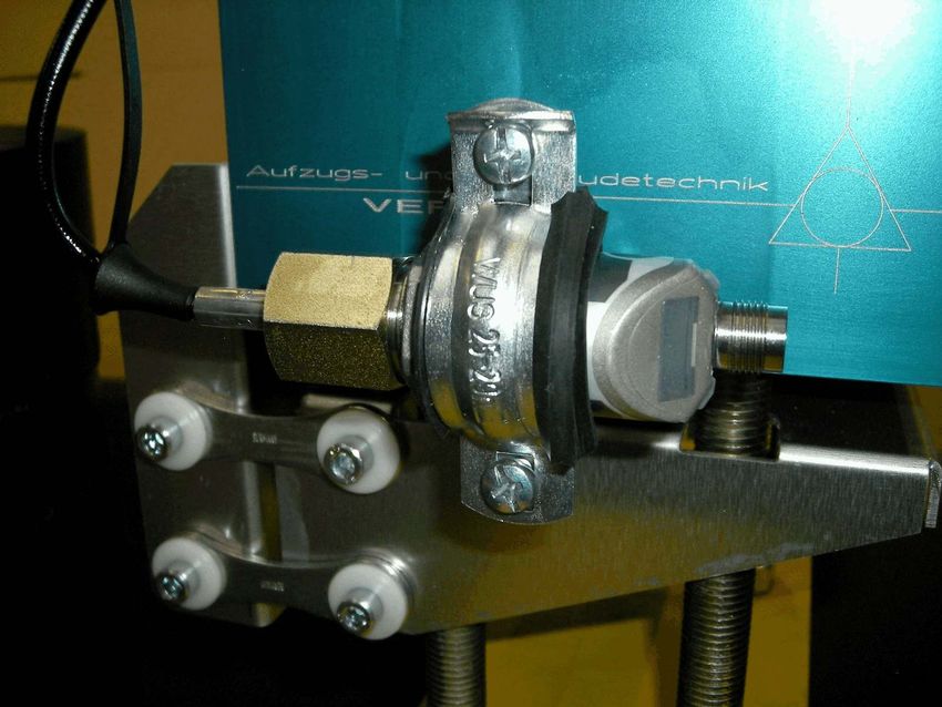
Beschreibung/Inbetriebnahme/Wartung                                   AS-GB-002/...
                                        Descrition/Installation/Maintenance                                   “balance”

         This unit serves as a load-compensating fixing element in applications where several ropes are used over shared
         guide pulleys or traction sheaves as load carriers.

         The major advantages compared to conventional load carrier connections with flexible compensation are:

         -       One hundred percent load compensation over the whole compensating travel!
         -       No time-consuming adjustment and inspection of rope tension.
         -       No contraction or extension on loading and offloading on the suspension
                 (–> system less resilient)
         -       straightforward recognition of incorrect rope elongation or restriction (optional) in accordance with EN81-1/2-
                 standards (sect. 14.1.2)
         -       Straightforward measurement of overload via an electronic pressure switch (optional) to comply with EN81-
                 1/2- requirements (sect.14.2.5).
         -       Single suspension designed for up to a breaking load of the corresponding maximum rope size -Corrosion-
                 resistant design (major parts are stainless steel!)
         -       Patented Design!

         1.1     Hydraulische Seilaufhängung - Basiseinheit / Hydraulic Rope-Suspension - Main
                 Unit
                 Die hydraulische Seilaufhängung stellt ein dauerhaft gleichm äßiges Tragen der Tragm ittel sicher. Jedes Seil
                 ist m it einer als Kolbenstange ausgebildeten Augenschraube verbunden, welche die Funktion eines
                 hydraulischen Zugkolbens hat. Das darin kom prim ierte Fluid kann dabei als nahezu inkom pressibel
                 betrachtet werden. Die Druckkam m ern jeder einzelnen hydraulischen Tragm ittelaufnahm e sind hydraulisch
                 m iteinander verbunden, so dass in jeder Druckkam m er der gleiche Druck herrscht. Som it werden alle
                 Tragm ittel m it der gleichen Kraft beaufschlagt und ein vollkomm ener Lastausgleich sichergestellt, auch wenn
                 sich ein Kolben auf Grund von Seillängung verschiebt.
                 Die Einheit wird m ontagefertig m it vorgefüllten Druckkam m ern angeliefert und bedarf keinerlei weiteren
                 hydraulischen Einstellungsarbeiten. Die Ölbefüllung ist so ausgelegt, dass bei gleichm äßiger Seillänge die
                 als Augenschrauben ausgebildeten Kolbenstangen genau in der Mitte des Hubbereiches stehen, so dass in
                 beide Richtungen (–> Seillängung und -kürzung) die gleichen W ege zur Verfügung stehen.
                 Da die Seilaufhängung je nach Basisgröße für eine bestim m te Anzahl Seile ausgeführt ist (z.B.: 5, 9 oder 13
                 Seile), wird die Einheit bei dazwischenliegender Anzahl von Seilen (z.B.: 7) m it der nächstgrößeren
                 Standardgröße und entsprechender Anzahl Verschlußkappen (bei 7 Seilen –> 2), welche die im Block nicht
                 benötigten Druckkam m ern verschließen, angeliefert. Norm alerweise werden hierbei im m er die äußeren
                 Aufhängungen verschlossen, so dass die angeschlossenen Seile kom pakt zusam m en bleiben.

                 The hydraulic rope-suspension ensures that the support of the load carrier is permanently stable. Each rope
                 is connected to an eye bolt, designed as a piston rod, which has the function of a hydraulic traction piston.
                 The fluid, which is compressed inside it can be regarded as more or less incompressible. The pressure
                 chambers of each hydraulic load carrier are hydraulically linked to each other, so that the pressure is the
                 same in each pressure chamber. In this way all load carriers are impacted with the sam e force, ensuring
                 complete load compensation, even if one piston should deviate due to rope elongation.
                 The unit is delivered ready for installation with pre-filled pressure chambers and does not require any further
                 hydraulic adjustment. The filling of oil is designed so that when the ropes are of equal length, the eye bolts
                 designed as piston rods, are exactly in the middle of the lifting range, so that the same distances are
                 available in both directions (–> rope elongation and restriction).
                 As the rope-suspension, depending on the basic parameter, is designed for a specific number of ropes (e.g.,
                 5, 9 or 13 ropes), should the number of ropes lie in between these sizes (e.g., 7 ropes) then the unit with the
                 next largest standard size and corresponding number of sealing caps, (for 7 ropes –> 2), will be delivered.
                 The sealing caps close the pressure chambers in the block that are not required. The outer suspensions are
                 normally always closed, so that the mounted ropes remain compact and together.

Dokument: as-gb-002_balance_betr_u_montageanleitung_maerz2021_.wpd   Revision: 29.03.2021    Seite / Page 3 von / of 25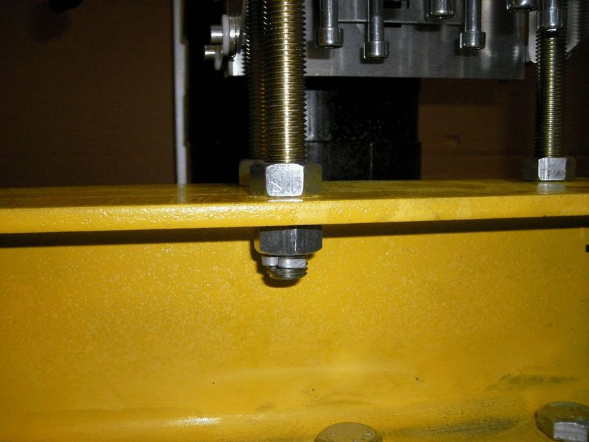
Beschreibung/Inbetriebnahme/Wartung                                               AS-GB-002/...
                                            Descrition/Installation/Maintenance                                               “balance”

                 Technische Daten / Technical Data:
                  Varianten (Seilgrößen + Anzahl Seile)       Seildurchm. / Diam. 6-8mm: Basis-Blockgrößen / Basic Size: 5, 9 o.13 Seile/Rop.
                  Variants (rope size + number of ropes)      Seildurchm. / Diam. 9-11mm: Basis-Blockgrößen / Basic Size: 5, 9 o13 Seile/Rop.
                                                              Seildurchm. / Diam. 12-14mm: Basis-Blockgrößen / Basic Size: 5,9 o.13 Seile/Rop.
                                                              Seildurchm. / Diam. 15-17mm: Basis-Blockgrößen / Basic Size: 5,9 o.13 Seile/Rop.

                  Auslegungslast pro Seil/Aufhängung          Größe/Size 6-8: 3'380 N          Größe/Size 9-11: 6'390 N
                  Design load per rope/suspension             Größe/Size 12-14: 10'280 N       Größe/Size 15-17: 14800 N

                  Bruchlast der Aufhängung                    Größe/Size 6-8: $40'560 N                  Größe/Size 9-11: $76'680 N
                  Break load of suspension                    Größe/Size 12-14: $123'360 N               Größe/Size 15-17: $177600 N

                  maximaler Ausgleichshub                     Größe / Size 6-8:                ± 47mm
                  –> bei gleichmäßiger Montage der Seile      Größe / Size 9-11:               ± 62mm
                  in Mittelstellung                           Größe / Size 12-14:              ± 69mm
                  max. compensating travel                    Größe / Size15-17:               ± 120mm
                  –> with uniform installation of all ropes
                  at middle position

                  Druckmedium / Hydraulic Fluid               Bio-Öl / Organic Oil (Rivolta S.B.H.23); nicht wassergefährdend / non water
                                                              polluting

                  Druck bei max. Auslegungslast der Seile     Größe / Size 6-8: 81 bar                   Größe / Size 9-11: 76 bar
                  Pressure at max. design load                Größe / Size 12-14: 80,5 bar               Größe / Size 15-17: 77 bar

                  Dichtungen / Seals                          NBR/PUR/POM

                  Material/Oberflächenschutz                  Block / Housing:            hochfeste Aluminiumlegierung 7075 mit spezieller
                  Material/Surface Protection                                             Harteloxalbeschichtung / high strength aluminium
                                                                                          alloy 7075, wirth special hard anodized surface
                                                              Kolbenstangen / Piston Rod: hochfester rostfreier Stahl / high strength stainless
                                                                                          steel
                                                              Kolben / Piston:            hochfester rostfreier Stahl / high strength stainless
                                                                                          steel
                                                              Zylinderkopf / Cyl. Head:   rostfreier Stahl / stainless steel
                                                              Zylinderrohr / Cyl. Tube:   S355, NiP (erst ab Seildurchmesser 15-17 / for rope
                                                                                          diameter equal or bigger than 15-17 only )
                                                              Gew.-stangen / Thread. Rods: 8.8, galvanisch verzinkt / galvanized

                  Temperaturbereich / Temp.-Range             -20/ .... + 50/C

                  Befestigungslochbild (Lastträger)*          Variante /05...08:      112 x 56 - M16     –> IPB 100
                  –> Lochbild ausgelegt für I-Träger ...      Variante /09...08:      150 x 66 - M16     –> IPB 120
                  Mounting hole pattern (load carrier)        Variante /13...08:      216 x 86 - M16     –> IPB 160
                  –> designed for I-Beam                      Variante /05...11:      142 x 66 - M20     –> IPB 120
                                                              Variante /09...11:      180 x 76 - M20     –> IPB 140
                                                              Variante /13...11:      275 x 110 - M24    –> IPB 200
                                                              Variante /05...14:      180 x 98 - M24     –> IPB 180
                                                              Variante /09...14:      220 x 98 - M24     –> IPB 180
                                                              Variante /13...14:      310 x 166 - M30    –> -------
                                                              Variante /05...14:      235 x 98 - M30     –> IPB 200
                                                              Variante /09...17:      280 x 100 - M30    –> -------
                                                              Variante /13...17:      400 x 210 - M36    –> -------

                  Einbaulage / Install.-Position              stehend oder hängend (über Kopf) / standing or hanging (overhead)

                  Schrägzug / Transversal tension             Max. zulässiger, festigkeitsbedingter Schrägzugwinkel an den als Kolbenstangen
                                                              ausgebildeten Augenschrauben: 8/
                                                              max. allowed angle for transversal tension (bending stress limit) at the piston rods
                                                              designed as eye-bolts: 8/
                                                              Zur Sicherstellung des reibungsarmen Lastausgleiches sollte der
                                                              Schrägzugwinkel jedoch nicht über 2/ liegen!
                                                              To ensure a low friction equalizing of all ropes, the angle of transversal
                                                              tension should be less than 2/!
                 *: Variantenschlüssel siehe auch Kap. 1.4 / Variant key see Chapter 1.4

Dokument: as-gb-002_balance_betr_u_montageanleitung_maerz2021_.wpd               Revision: 29.03.2021        Seite / Page 4 von / of 25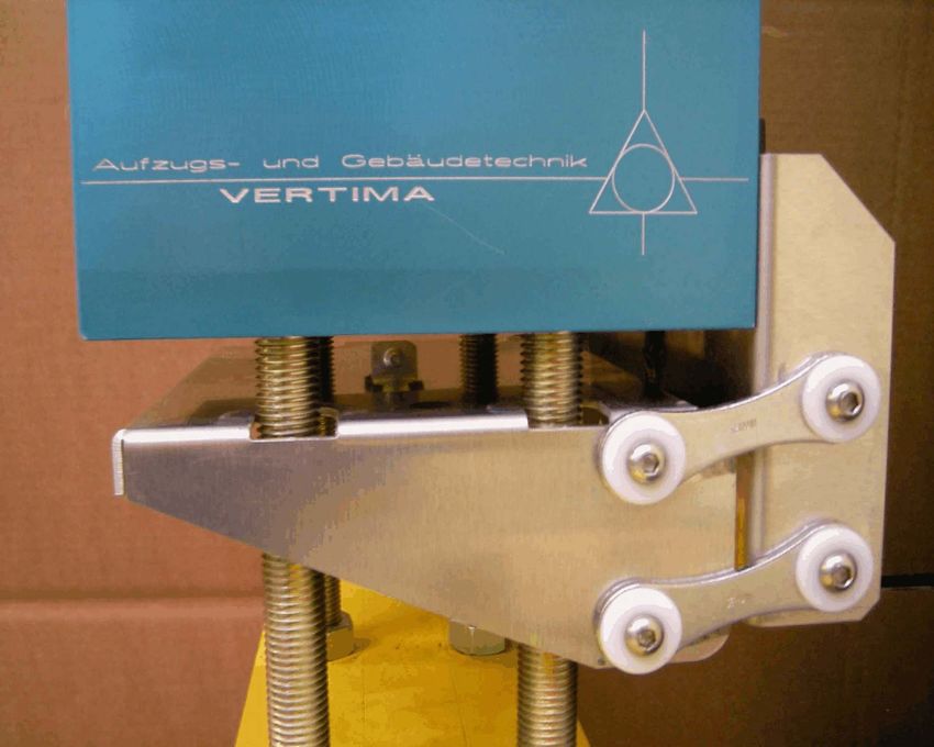
Beschreibung/Inbetriebnahme/Wartung                                  AS-GB-002/...
                                        Descrition/Installation/Maintenance                                  “balance”

Dokument: as-gb-002_balance_betr_u_montageanleitung_maerz2021_.wpd   Revision: 29.03.2021   Seite / Page 5 von / of 25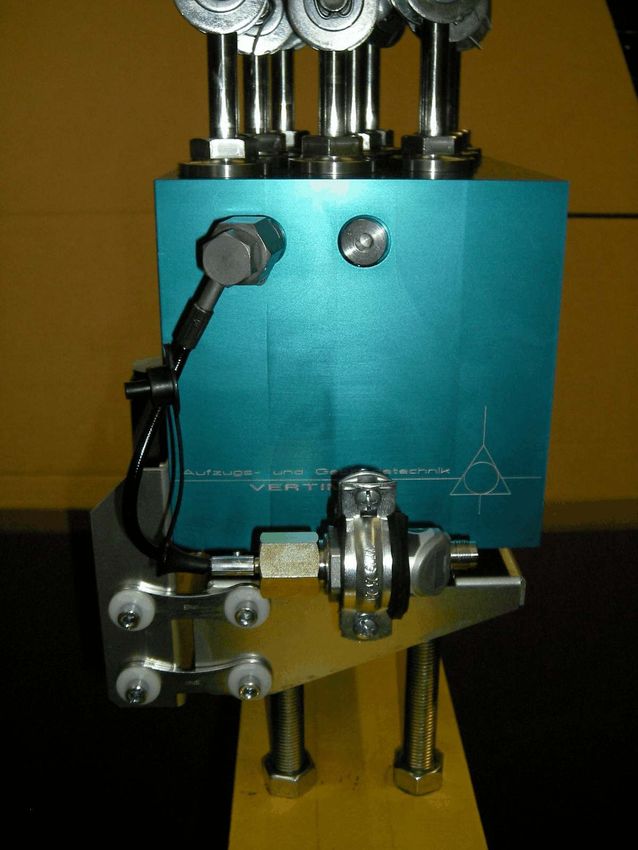
Beschreibung/Inbetriebnahme/Wartung                                  AS-GB-002/...
                                        Descrition/Installation/Maintenance                                  “balance”

Dokument: as-gb-002_balance_betr_u_montageanleitung_maerz2021_.wpd   Revision: 29.03.2021   Seite / Page 6 von / of 25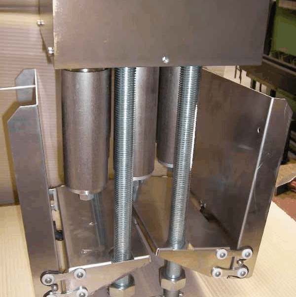
Beschreibung/Inbetriebnahme/Wartung                                  AS-GB-002/...
                                        Descrition/Installation/Maintenance                                  “balance”

Dokument: as-gb-002_balance_betr_u_montageanleitung_maerz2021_.wpd   Revision: 29.03.2021   Seite / Page 7 von / of 25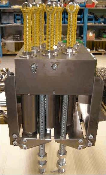
Beschreibung/Inbetriebnahme/Wartung                                  AS-GB-002/...
                                        Descrition/Installation/Maintenance                                  “balance”

Dokument: as-gb-002_balance_betr_u_montageanleitung_maerz2021_.wpd   Revision: 29.03.2021   Seite / Page 8 von / of 25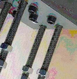
Beschreibung/Inbetriebnahme/Wartung                                  AS-GB-002/...
                                        Descrition/Installation/Maintenance                                  “balance”

Dokument: as-gb-002_balance_betr_u_montageanleitung_maerz2021_.wpd   Revision: 29.03.2021   Seite / Page 9 von / of 25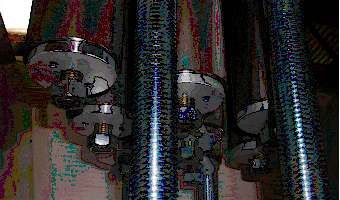
Beschreibung/Inbetriebnahme/Wartung AS-GB-002/...
Descrition/Installation/Maintenance “balance”
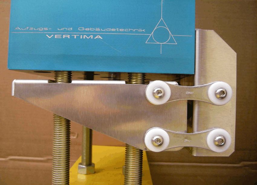
1.2 Option: Schlaffseilwippe / Option Slack Rope Rocker
Zur Erkennung einer unzulässigen Seillängung
(gem äß EN81-1/2-Kap. 14.1.2) kann die Einheit
optional m it einer Schaltwippe ausgerüstet
werden, welche alle Seilaufhängungen über-
wacht. Bei fehlerhafter Längung eines oder
m ehrerer Seile wird die W ippe über die nach
unten aus dem Block fahrenden
Kolbenverlängerung nach unten ausgelenkt und
der daran verbundene Sicherheitsschalter über
eine Schaltgabel betätigt.
To identify incorrect rope elongation (in acc.
with EN81-1/2 section 14.1.2) the unit can be
fitted with an optional slack rope rocker, which
monitors all of the rope-suspensions. Should
the elongation of one or more ropes be faulty,
the rocker will be deflected over the piston Schaltwippe in neutraler Stellung / Slack Rope Rocker in
elongation moving downwards out of the block. neutral position
The safety switch, w hich is connected to it will
be activated via a shift fork.
Technische Daten / Technical Data:
Schaltfunktion / Switching function Öffner/Schließer NC / NO
Schaltertyp / Type of switch Sprungschalter ohne Kontaktüberdeckung / Snap action w/o contact overlap
Schutzart / Protection IP 67
Gehäuse / Housing Kunststoff / Plastic
Spannung / Voltage 12 .... 230 VDC / VAC
Max. Schaltleistung / max. switching capacity 250 VAC- 4A
Bei größeren Modellen (ab
Größe 0514) werden aus
k o nstruk tive n G rü n d e n
zwei Einzelwippen geliefert,
welche rechts und links am
Block m ontiert werden! Die
b e i d e n
Überwachungsschalter zur
Schlaffseilerkennung sind
dann elek trisch in R eihe
anzuschließen.
In fact of the size for bigger
m o d e l s ( a b o v e v a r ia n t
0514) the slac k ro p e
detec tion is d esigned in
tw o, m irrored units. The
control switches have to be
c o n n e c te d in s e rie s fo r
slack rope detection.
Ausführung m it zwei Einzelwippen (hier Baugröße “0917")
System with two (mirrored) rockers (shown at variant “0917")
Dokument: as-gb-002_balance_betr_u_montageanleitung_maerz2021_.wpd Revision: 29.03.2021 Seite / Page 10 von / of 25Beschreibung/Inbetriebnahme/Wartung AS-GB-002/...
Descrition/Installation/Maintenance “balance”
1.3 Option: Überlasterkennung / Option: Overload detection
Z u r E rk ennung des B eladezusta n d e s b zw . vo n
unzulässiger Überlast, steht optional ein elektronischer
Druckschalter zur Verfügung. Dieser kann sehr einfach
am seitlich befindlichen MiniMess-Anschluss m it einer
kurzen Schlauchleitung angeschlossen werden und am
Zylinderblock der Ausgleichseinheit befestigt werden.
Hierbei entsteht keinerlei Ölaustritt und beeinflußt deshalb
auch nicht den korrekten Ölfüllstand der Aufhängungen.
Som it ist der Anbau an die Einheit ein Aufwand von nur
wenigen Minuten.
Der Schalter selbst wird über das m itgelieferte Kabel an
die Steuerung angeschlossen und m it dem M12x1-
Stecker m it dem Druckschalter verbunden.
Bevor dieser dann m it einer Schelle am Zylinderblock der
Einheit befestigt wird, kann dieser in einer zum Ablesen
günstigen Position gehalten und entsprechend der unter Detail Druckschalter / Detail Pressure Switch
Kap. 2.3 beschriebenen Anleitung eingestellt werden.
Der speziell abgestim m te elektronische Druckschalter verfügt über 2 frei program m ierbare Schaltpunkte.
Som it kann beispielsweise ein Schaltpunkt zur Erkennung der Überlast (gem . EN81-1/2-Kap. 14.2.5) und der
andere Schaltpunkt zur Erkennung der Maxim allast während der Fahrt oder aber auch zur Erkennung einer
unzulässigen Minim allast genutzt werden.
An optional electronic pressure switch is available to identify the load status or incorrect overload. This can
easily be connected to the MiniMess connection, which is located on the side of the unit, via a short hose line
and fixed on the cylinder block of the compensating unit. In doing so there is no oil spill and it does not affect
the correct oil level of the suspensions. Consequently it takes only a few minutes to mount it onto the unit.
The switch itself is connected to the control system with the rope supplied and connected via the M12x1-plug
with the pressure switch.
Before this is attached to the cylinder block of the unit with a clamp, it can be held in a suitable position for
reading and setting as described in the instructions in section 2.3.
The specially adapted electronic pressure switch has 2 freely programmable switching points. It has a
switching point to identify overload (in accordance with EN81-1/2 section 14.2.5) and the other switching
point can be used, for example, to identify maximum load during the ride or to identify an incorrect minimum
load.
HINW EIS: Bei ansteigendem Schrägzug an den als Kolbenstangen ausgebildeten Augenschrauben
verschlechtert sich die M eßgenauigkeit zw angsläufig durch die querkraftbedingte Reibung in den
Führungselementen von Kolben und Kolbenstange! (Siehe hierzu auch Tabelle in Kap. 1.1)
Remark: With increasing transversal tension at the end of the eye-bolts (= piston rod) the accurancy
of the load measuring system is affected by the increased side load on the guiding rings of the
cylinder-head resp. the piston! (See also table in Chapter 1.1)
Dokument: as-gb-002_balance_betr_u_montageanleitung_maerz2021_.wpd Revision: 29.03.2021 Seite / Page 11 von / of 25Beschreibung/Inbetriebnahme/Wartung AS-GB-002/...
Descrition/Installation/Maintenance “balance”
Technische Daten / Technical Data:
Schaltpunkte, Hysterese SP1 / RP1 und SP2 / RP2 frei
Switching Points, Hysteresis einstellbar / freely adjustable
Druckbereich / Press.-Range 0-100 bar oder / or 0-40 bar
Überlastbereich der Messzelle 200 bar
/ Limit pressure for accurancy
Berstdruck / Burst Pressure 500 bar
Schutzart / Protection IP67 (bei Verwendung einer
IP67 Kupplungsdose)
Gehäuse / Housing Edelstahl/Kunststoff
Spannung / Voltage 24 VDC
Max. Schaltleistung / Max. 250 mA
switching capacity
Lebensdauer (Schaltzyklen) > 100 Millionen
A n g e b a u te r D r u c k s c h a lte r / In s ta lle d
Pressure Switch
1.4 Variantenschlüssel / Variant Code
Die m öglichen Varianten für die Größe und Anzahl der Seile bzw. die m öglichen Optionen werden bei der
Part-Num m er wie folgt berücksichtigt / The possible variants for the size and num ber of ropes or possible
options for part numbers are as follows:
Erste beiden Stellen / First two digits Zylinderblock Basisvariante (= max. Mögliche Anz. Seile): z.B. 05; 09; 13
Zweite beiden Stellen / Second two digits genutzte Anzahl Seile: z.B.: 07 used number of ropes: e.g.: 07
Nachfolgende 2 Stellen / following two digits Seildurchmesser / Diam.: 08: –> 6-8mm 11: –> 9-11mm
14:–> 12-14mm 17:–> 15-17mm
Optionen / Options mit zusätzlicher Schaltwippe: -W
mit zusätzlicher Überlasterkennung (2 Schaltpunkte): -Ü2
Bsp./Example 1: AS-GB-002/090908-W –> Zylinderblock für m axim al 9 Seile; 9 Seile im Einsatz;
S e ils c h lo ß 6 -8 m m ; m it O p tio n S c h a lte r w ip p e zu r
Erkennung von unzulässiger Längung der Seile
–> Cylinder block for a maximum of 9 ropes; 9 ropes in
use; Rope lock 6-8mm; 2 sockets with sealing caps; with
option of a rocker switch to identify incorrect elongation of
ropes
Bsp./Example 2: AS-GB-002/090811-W -Ü2 –> Zylinderblock für m axim al 9 Seile; 8 Seile im Einsatz;
Seilschloß 9-11m m ; eine Aufnahm e mit Verschlusskappe;
m it der O ption S c ha lterw ipp e zur E rk en nu ng von
u n zu lä s s ig e r L ä n g u n g d e r S e ile ; m it d e r O p tio n
D ru c k s c h a lte r zu r Ü b e rla s te rk e n n u ng (2 fre i
program m ierbare Lastpunkte)
–> Cylinder block for a maximum of 9 ropes; 8 ropes in
operation; rope lock 9-11mm; a sealing cap; with the
option of a rocker switch to detect incorrect elongation of
ropes; with the option of a pressure switch to detect
overload (2 freely programmable load points)
Dokument: as-gb-002_balance_betr_u_montageanleitung_maerz2021_.wpd Revision: 29.03.2021 Seite / Page 12 von / of 25Beschreibung/Inbetriebnahme/Wartung AS-GB-002/...
Descrition/Installation/Maintenance “balance”
2 Montage - Inbetriebnahme / Installation - Operation
ACHTUNG: Die als Augenschrauben ausgebildeten Kolbenstangen dürfen vor Inbetriebnahm e nicht in den Block
gedrückt werden, da sonst ungewollt Luft eingesaugt werden kann!
Deshalb sind diese bei Anlieferung durch Arretierbolzen, welche an der Blockunterseite eingeschraubt fixiert!
Nachdem die Seile m ontiert sind m üssen diese Bolzen vor Inbetriebnahm e der Einheit entfernt werden!
W ARNING: The hydraulic piston rods, designed as eye-bolts, m ust not be m oved in the housing before starting-up,
because this can cause sucked air in the hydraulic cham bers resp. a tem porary leakage of the rod seal as a result
of negativ pressure.
Therefore the piston rods are fixed by locking bolts, which are installed on the lower side of the housing. This
enables easy installation of the ropes without loosing the ideal center-position of the piston rods. After installation of
alle ropes this bolts have to be rem oved to activate the balance function!
2.1 Basiseinheit - Seilaufhängung / Base Unit - Rope-Suspension
Die hydraulische Seilaufhängung wird m it den 4 unten am Zylinderblock befindlichen (eingeklebten)
Gewindestangen (Festigkeitsklasse 8.8) am vorgesehenen Lastträger befestigt (Lochbild siehe Kap. 1.1).
Das Lochbild ist jeweils so ausgelegt, dass dieses m it der norm gerechten Bohrungsanordnung an einem
zugehörigen I-Träger korrespondiert (siehe Kap. 1.1).
The hydraulic rope-suspension is attached to the designated load support with/via the 4 threaded rods
(strength category 8.8), which are situated on the underside of the cylinder block (glued) (see section 1.1
hole pattern). The hole pattern is designed in each case to correspond with the standard hole arrangement
on the appropriate I-beam. (see section 1.1).
Die Gewindestangen sind m it je 2 Muttern und einem Splint vorm ontiert. Bei der Montage wird zunächst der
Splint und die untere Mutter entfernt. Dann wird die obere Mutter an allen 4 Gewindestangen gleich weit
eingedreht u nd die G e w in d e s ta n g e n d u rc h die
Bohrungen des Trägers gesteckt.
Bei stehender Montage wird die Einheit m it den 4
Gewindestangen in die Durchgangsbohrungen des
Befestigungsträgers gestellt. D anach werden die
unteren Muttern wieder bis über die Spintbohrungen
aufges c h ra u b t u n d d ie S p lin te ordn un gs ge m äß
m ontiert u nd a ufg eb og en . D urc h gleichm äßiges
Verdrehen der oberen Muttern wird die Einheit nun auf
die g ew üns c hte H öhe und gleichzeitig lotrechte
Ausrichtung gebracht. Es ist dabei darauf zu achten,
dass am Ende alle 4 oberen Muttern an der Oberseite
des Befestigungsträgers anliegen. Die Ausrichtung
kann beispielsweise m ittels einer W asserwaage an
den Außenflächen des würfelförm igen Zylinderblocks
oder über die gleichm äßigen Abstände der Muttern
zur Blockunterseite geprüft werden. Splintsicherung nicht vergessen / Do not forget
split pin for securing threaded rods
Hinweis: Bei der Festlegung der Montagehöhe ist auf ausreichenden Abstand zur Entnahm e der
Arretierbolzen bzw. ausreichend Betätigungsweg für die optionale Schlaffseilwippe zu achten.
Danach werden die unteren Muttern von Hand bis zum Berühren der Unterseite des Befestigungsträgers
gedreht und anschließend im ständigen W echsel gleichm äßig festgezogen (Anzugsm om ent siehe
nachfolgende Tabelle).
Bei Überkopfm ontage (hängend) ist die Vorgehensweise sinngem äß ähnlich, allerdings m uss die Einheit
zunächst fachgerecht vor Herabfallen gesichert werden, bis alle 4 entfernten Muttern wieder bis über die
Splintbohrungen aufgeschraubt und die Splinte ordnungsgem äß gesteckt und aufgebogen sind.
Dokument: as-gb-002_balance_betr_u_montageanleitung_maerz2021_.wpd Revision: 29.03.2021 Seite / Page 13 von / of 25Beschreibung/Inbetriebnahme/Wartung AS-GB-002/...
Descrition/Installation/Maintenance “balance”
Durch gleichm äßiges Verdrehen der oberen Muttern wird die Einheit nun auf die gewünschte Höhe und
gleichzeitig lotrechte Ausrichtung gebracht. Es ist dabei darauf zu achten, dass am Ende wieder alle 4
oberen Muttern an der Oberseite des Befestigungsträgers anliegen. Die Ausrichtung erfolgt wie vor
beschrieben.
Hinweis: Siehe oben!
Danach werden die unteren Muttern bis zum Berühren der Unterseite des Befestigungsträgers von Hand
gedreht und anschließend im ständigen W echsel gleichm äßig festgezogen (Anzugsm om ent siehe
nachfolgende Tabelle).
The threaded rods are pre-assembled with 2 nuts and a split pin each. During installation, the cotter pin and
the lower nut are removed first. Then the upper nut is screwed in equally far on all 4 threaded rods and the
threaded rods are inserted through the holes in the support.
W hen the unit is mounted upright, the 4 threaded rods are placed in the through holes of the mounting
bracket. Then the lower nuts are screwed back on up to over the spint holes and the cotter pins are properly
fitted and bent up. By twisting the upper nuts evenly, the unit is now brought to the desired height and at the
same time plum b. Make sure that at the end all 4 upper nuts are in contact with the top of the mounting
bracket. The alignment can be checked, for example, by means of a spirit level on the outer surfaces of the
cube-shaped cylinder block or via the even distances between the nuts and the underside of the block.
Note: W hen determining the mounting height, ensure that there is sufficient distance to remove the locking
bolts or sufficient actuation travel for the optional slack rope rocker
Then turn the lower nuts by hand until they touch the underside of the mounting bracket and then tighten
them evenly in continuous alternation (for tightening torque, see table below).
For overhead mounting (hanging position) the procedure is similar, but the unit must first be properly secured
against falling down until all 4 removed nuts are screwed back on over the cotter pin holes and the cotter
pins are properly inserted and bent open.
By evenly turning the upper nuts, the unit is now brought to the desired height and at the same time plumb.
Make sure that at the end all 4 upper nuts on the top of the upper nuts are in contact with the upper side of
the mounting bracket. Alignment is carried out as described above. described above.
Note: See above!
Then turn the lower nuts by hand until they touch the underside of the fastening bracket and then tighten
them evenly in continuous alternation (for tightening torque, see the following table).
Dokument: as-gb-002_balance_betr_u_montageanleitung_maerz2021_.wpd Revision: 29.03.2021 Seite / Page 14 von / of 25Beschreibung/Inbetriebnahme/Wartung AS-GB-002/...
Descrition/Installation/Maintenance “balance”
Em pfohlene Anzugsm om ente (Festigkeitsklasse 8.8) / Recommended torque for the bolts (strength 8.8):
M16 172 Nm
M20 347 Nm
M24 550 Nm
M30 800 Nm
M36 1000 Nm
Hinweis: Für die ausreichende Festigkeitsauslegung des
Lastträgers ist der Betreiber verantwortlich!
Please note: The operater is responsable for the adequate
m echanical strength of the load carrier!
Danach sind die losen Seile wie gewohnt in die Seilschlösser
einzuführen, auf die korrekte Länge zu bringen und festzuziehen.
Für eventuelle Korrekturen em pfiehlt es sich hierbei zunächst die
aus dem Seilschloß ragende Restlänge ca. 0,4...0,6m länger zu
lassen, um ggf. nachlängen zu können.
Nachdem alle Seile auf die benötigte Länge eingestellt sind und
ungefähr die gleiche Vorspannkraft aufweisen, werden die Seile mit
Seilendklem m en gesichert. Hierbei ist zu beachten, dass der Bei der Montage sind zunächst alle
Rundbügel nicht auf das tragende Seilende, sondern auf das Seile m it ungefähr gleicher
überstehende Reststück drückt (–> Kerbwirkung!). Vorspannkraft aufzulegen / Ensure
that all rope locks are approx. installed
The slack ropes are to be inserted into the rope locks as norm al, with the same preload
adjusted to the correct length and tightened. In case correction is
necessary, leaving a rope rest of approximately 0.4 to 0.6m protruding from the rope lock is recommended,
to enable lengthening where necessary.
W hen all of the ropes have been adjusted to approximately the same length, the ropes must be secured with
the rope end clamps provided. Please note that the securing element does not press on the bearing rope but
on the protruding remaining rope (–> notch effect!),
L Danach sind die Arretierbolzen an der Blockunterseite zur Aktivierung des
Systems zu entfernen.
L After this the Locking Bolts at the lower side of the housing have to be removed
to activate the balance-function.
Bei Systemen mit Schlaffseilw ippe wird diese erst nach dem Entfernen der Arretierbolzen nach
oben geschoben und mit dem Block verschraubt!
Systems with slack-rope-detection (–> slack rope rocker): The slack rocker unit is m oved up and
fixed to the housing not before the locking bolts are removed.
Dokument: as-gb-002_balance_betr_u_montageanleitung_maerz2021_.wpd Revision: 29.03.2021 Seite / Page 15 von / of 25Beschreibung/Inbetriebnahme/Wartung AS-GB-002/...
Descrition/Installation/Maintenance “balance”
Nach der “Aktivierung” des System s (–> hydraulischer Lastausgleich zwischen den Seilen) ist die Lage der
als Kolbenstange ausgebildeten Augenschrauben nochm als auf die korrekte Position zu überprüfen. Sollten
s ich hierbei unzuläs s ige V e rs c h ie b u n g e n ze ig e n , s in d g e g e b e n fa lls die S eillängen nochm als
nachzujustieren. Im Idealfall sollten bei Inbetriebnahm e alle Seilschlösser auf fast gleichem Niveau stehen.
W hen the load has been applied to the ropes, the correct position of the eyebolts designed as piston rods
should again be verified. Should incorrect displacement be observed, the ropes are to be unloaded once
again and re-adjusted. In best case, all rope locks are nearly at same level.
Dokument: as-gb-002_balance_betr_u_montageanleitung_maerz2021_.wpd Revision: 29.03.2021 Seite / Page 16 von / of 25Beschreibung/Inbetriebnahme/Wartung AS-GB-002/...
Descrition/Installation/Maintenance “balance”
2.2 Schlaffseilwippe (Option -W) / Slack Rope Rocker (Option -W)
Zur Erkennung unzulässiger Seillängung kann optional,
wie unte r K a p . 1.2 beschrie b e n, eine S chaltw ippe
vorgesehen werden. Diese ist bei Bestellung bereits
vorm ontiert, kann aber bei Bedarf auch nachgerüstet
werden.
Nachdem die Einheit, wie unter Kap. 2.1 beschrieben,
befes tig t u nd die S eile ju s tie rt w u rd e n , s o llte die
S c h a ltw ip p e s o aus geric htet s ein, d a s s d e r
Sprungschalter nicht betätigt ist. Eine Betätigung soll erst
bei unzulässiger Längung eines oder m ehrerer Tragm ittel
erfolgen.
In order to identify incorrect rope elongation an optional
rocker switch, as described in Section 1.2, can be fitted.
W hen ordered it is already fitted, but it can also be
retrofitted as required. After the unit, as described in
Section 2.1, has been secured and the ropes aligned, the
rocker sw itch should be adjusted so that the snap action
switch is not activated. This should only be activated if
incorrect elongation of one or several supports occurs.
Da die Arretierbolzen bei Inbetriebnahm e entfernt werden
m üssen, wird die Schaltwippe meist lose beigelegt. Diese
w ird d a n n b e i d e r M o n ta g e ü b e r d ie S te h b o lze n
g e s c h o be n und erst nach dem E ntfe rn e n d e r
Arretierbolzen m it dem Block verschraubt.
Because the locking bolts have to be removed for
starting-up the system, the slack rocker unit is normally
not pre-installed. At the end of the installation this unit is
placed above the threaded rods of the housing and fixed
Doppelte Schaltwippe bei großen Modellen /
to the housing (alum. block).
Double Slack Rope Rocker for bigger models
Schaltwippe in unterer (geschalteter) Stellung /
Slack Rope Rocker at lower (activated) position
Dokument: as-gb-002_balance_betr_u_montageanleitung_maerz2021_.wpd Revision: 29.03.2021 Seite / Page 17 von / of 25Beschreibung/Inbetriebnahme/Wartung AS-GB-002/...
Descrition/Installation/Maintenance “balance”
2.3 Überlasterkennung (Option -Ü2) / Overload detection (Option -Ü2)
Zur Erkennung von Überlast bzw. definierten Beladezuständen kann
optional, der unter Kap. 1.3 beschriebene Druckschalter eingesetzt
werden.
D ie s e r w ir d zu r M o n ta g e a n d e m s e itlic h v o r h a n d e n e n
Minim essanschluß angeschlossen. Der Druckschalter wird hierzu an
s e i n e m h yd r a u lis c h e n A n s c h lu s s G 1 / 4 " m i t d e m g e r a d e n
A ns c h lu ß s tü c k d e r k le in e n Ve rb indu ng s leitung angeschlossen
(Anzugsm om ent: 10Nm ). Danach wird die gerändelte Schutzkappe am
seitlichen MiniMess-Anschluss abgenom m en und die 90/-Kupplung
des anderen Schlauchendes m it dem Zylinderblock verbunden. Da die
Kupplung leckagefrei konzipiert ist, tritt dabei kein Öl aus.
An optional pressure switch as described in Section 1.3 can be fitted in
order to detect an overload or defined load status.
This is connected to the MiniMess connection, which is located on the
side of the unit, on installation. The pressure switch is connected to its
hydraulic connection G1/4“ with the straight connecting piece of the
small connecting hose (torque: 10Nm). Then the knurled protective cap
is taken off the MiniMess connection and the 90/-coupling of the other Mit angebauter Lastm essung /
end of the hose connected with the cylinder block. W ith installed overload detection
As the coupling is leak-proof, so no oil does escape while connecting. (Electr. Press. Switch)
Das Kabel ist entsprechend dem elektrischen Schaltbild bzw. dem elektrischen Schaltplan an der Steuerung
anzuschließen. Danach wird der M12-Rundstecker am Druckschalter angeschlossen und Sensor wie
nachfolgend beschrieben eingestellt und der Schalter m it der Rohrschelle am Zylinderblock befestigt.
The electr. cable is then connected to the control system according to the electrical wiring or circuit diagram.
The M12 circular connector is then connected to the pressure switch and the sensor adjusted as described
below. The switch is attached to the cylinder block with the pipe clamp.
Die Einstellung vom Druckschalter erfolgt m ittels den beiden Tasten oberhalb vom Display / The Pre-Setting
is achieved by two buttons on top of the housing:
Linke Taste / Left Button: - Im Menü absteigend / scroll down menu
- W ert vergrößern / increase value
- W ird die Taste länger gedrückt erfolgt ein Schnelldurchlauf der
Param eterwerte / pressing longer time speeds up scrolling
Rechte Taste / Right Button: - Auswahl Menüpunkt / select menu
- W ert bestätigen / confirm value
Nach dem Einschalten der Versorgungsspannung vom Drucksensor zeigt das Gerät kurz “EdS” und beginnt
m it der Anzeige des aktuellen Druckes. Zur Überprüfung in welcher Einheit der Druck dargestellt wird, ist die
rechte Bedientaste zu drücken. Je nach Einstellung erscheint “bAr” (Einheit Bar), MPA (Einheit Mpa) oder
PSi (Einheit psi).
After switching on the supply voltage of the pressure sensor the unit briefly displays the letters “EdS” and
begins by displaying the current pressure. To inspect in which unit the pressure is being displayed, press the
right key. Depending on the setting the letters “bAr” (unit Bar), the letters MPA (unit Mpa) or PSi (unit psi) are
displayed.
Entsprechend den Schaltzuständen passt sich die Hintergrundbeleuchtung vom Display an / depending on
the relay status the bachground colour of the display changes:
–> Schaltausgang inaktiv / relay output inactive = grün / green
–> Schaltausgang aktiv / relay output active = rot / red
Ferner ist die H intergrundbeleuchtung vom Display in zwei Seiten unterteilt / the background colour is
devided in two areas
–> linke Seite Schaltausgang 1 / left side –> status of output 1
Dokument: as-gb-002_balance_betr_u_montageanleitung_maerz2021_.wpd Revision: 29.03.2021 Seite / Page 18 von / of 25Beschreibung/Inbetriebnahme/Wartung AS-GB-002/...
Descrition/Installation/Maintenance “balance”
–> rechte Seite Schaltausgang 2 / right side –> status of output 2
Darstellung der Digitalanzeige / Digital Representation:
Bezeichnung / Description Darstellung / Display
Schaltpunkt, Ausgang 1 Switching Point, Output 1 SP1
Rückschaltpunkt, Ausgang 1 Reseat Point, Output 1 rP1
Schaltpunkt, Ausgang 2 Switching Point, Output 2 SP2
Rückschaltpunkt, Ausgang 2 Reseat Point, Output 2 rP2
Druckfenster oberer Wert, Ausgang 1 Press. Window Upper Level, Output 1 FH1
Druckfenster unterer Wert, Ausgang 1 Press. Window Lower Level, Output 1 FL1
Druckfenster oberer Wert, Ausgang 2 Press. Window Upper Level, Output 2 FH2
Druckfenster unterer Wert, Ausgang 2 Press. Window Lower Level, Output 2 FL2
Erweiterte Funktionen Advanced Functions EF
Rücksetzen Reset rES
Schaltverzögerungszeit, Ausgang 1 Delay Switching Output 1 dS1
Schaltverzögerungszeit, Ausgang 2 Delay Switching Output 2 dS2
Rückschaltverzögerungszeit, Ausgang 1 Delay Reset Output 1 dr1
Rückschaltverzögerungszeit, Ausgang 2 Delay Reset Output 2 dr2
Ausgang 1 Output 1 ou1
Ausgang 2 Output 2 ou2
Schließer bei Hysteresefunktion NO for Hysteresis Function Hno
Schließer bei Fensterfunktion NO for Window Function Fno
Öffner bei Hysteresefunktion NC for Hysteresis Function Hnc
Öffner bei Fenster Funktion NC for Window Function Fnc
Einheitenumschaltung Unit Conversion Uni
Einheit bar Unit bar bAr
Einheit MPa Unit MPa MPA
Einheit psi Unit psi PSi
Max- Wert Max Value Hi
Fehleranzeige Error Err
Löschen Erase ---
Erweiterte Funktionen Advanced Functions EF
Ja Yes YES
Nein No no
Version Version VEr
Hinw eis:
- Übersteigt der aktuelle Druck den Nenndruck des Gerätes, so kann er nicht m ehr angezeigt
werden. In der Anzeige blinkt der m ax. Nenndruck. Als Folge blinkt bei Anwählen des
Menüpunktes Max- W ert (Hi) der hier gespeicherte Messwert des höchsten gem essenen
Druckes bis ein Rücksetzen (rES) erfolgt.
- Liegt der aktuelle Druck unterhalb 0,6% des Nennbereiches, so wird 0 bar angezeigt.
Dokument: as-gb-002_balance_betr_u_montageanleitung_maerz2021_.wpd Revision: 29.03.2021 Seite / Page 19 von / of 25Beschreibung/Inbetriebnahme/Wartung AS-GB-002/...
Descrition/Installation/Maintenance “balance”
Note:
- If the current pressure exceeds the unit’s nom inal pressure, then it can no longer be displayed.
The m axim um nom inal pressure then flashes in the display. As a result, on selecting the
m axim um value (Hi) in the m enu, the value of the highest pressure stored flashes until it is reset
(rES).
- If the current pressure is below 0.6% of the nom inal pressure, the display shows 0 bar.
Für beide Schaltausgänge kann ein Schaltpunkt und ein Rückschaltpunkt eingestellt werden. Der jeweilige
Ausgang schaltet wenn der eingestellte Schaltpunkt erreicht wurde und schaltet zurück, wenn der
Rückschaltpunkt unterschritten wurde.
One switching point and one shift point can be set for both relay outputs. The corresponding output switches
when the set switching point is reached. It switches back if it drops below the shift point.
Einstellbereiche für die beiden Schaltausgänge / Setting range for both relay outputs:
Untere Grenze / Lower Limit [RP]: 1,0 bar
Obere Grenze / Upper Limit [SP]: 100 bar
Min. Abstand zwischen RP und SP / min. distance between RP and SP: 1,0 bar
Raster / Raster: 0,2 bar
Hinw eis:
- Erfolgt ca. 60 sec. lang keine Tastenbetätigung, wird das Menü autom atisch beendet, ohne dass
eventuelle Änderungen wirksam werden.
- Bei gleichzeitigem Betätigen beider Tasten wird das Menü autom atisch beendet und die
vorgenom m enen Änderungen werden übernom m en.
- Beim Übernehm en eines eingestellten Param eters wird der Einstellwert eine Sekunde angezeigt,
bevor ein Rücksprung auf den entsprechenden Menüpunkt erfolgt.
Note:
- If a key is not pressed for approx. 60 sec., the menu closes automatically without adopting any
changes.
- If both keys are pressed at the same time, the menu closes automatically and the changes made
are adopted.
- W hen a set parameter is adopted the set level is shown for one second before switching back to
the corresponding menu item.
Elektroplan für Überlasterkennung m it Druckschalter EDS8446-2 / W iring diagramm for overload-detection
with electron. pressure switch EDS8446-2
Dokument: as-gb-002_balance_betr_u_montageanleitung_maerz2021_.wpd Revision: 29.03.2021 Seite / Page 20 von / of 25Beschreibung/Inbetriebnahme/Wartung AS-GB-002/...
Descrition/Installation/Maintenance “balance”
Einstelltabelle / Table of settings:
Basisgröße (Seildurchmesser) Anzahl aufgelegter Seile Druckerhöhung pro 100 daN (=kg) Gesamtlast
Basic Size (Rope diameter) (restliche verschlossen) an der Seilaufhängung
Number of ropes installed Pressure increase per 100 daN (=kg) total load
(others plugged) applied to rope-suspension
3 8,0 bar
4 6,0 bar
5 4,8 bar
6 4,0 bar
7 3,4 bar
6-8 8 3,0 bar
9 2,7 bar
10 2,4 bar
11 2,2 bar
12 2,0 bar
13 1,85 bar
3 4,0 bar
4 3,0 bar
5 2,4 bar
6 2,0 bar
7 1,7 bar
9-11 8 1,5 bar
9 1,3 bar
10 1,2 bar
11 1,1 bar
12 1 bar
13 0,92 bar
3 2,7 bar
4 2,0 bar
5 1,6 bar
6 1,3 bar
7 1,1 bar
8 1,0 bar
12-14
9 0,9 bar
10 0,81 bar
11 0,74 bar
12 0,68 bar
13 0,62 bar
Dokument: as-gb-002_balance_betr_u_montageanleitung_maerz2021_.wpd Revision: 29.03.2021 Seite / Page 21 von / of 25Beschreibung/Inbetriebnahme/Wartung AS-GB-002/...
Descrition/Installation/Maintenance “balance”
Basisgröße (Seildurchmesser) Anzahl aufgelegter Seile Druckerhöhung pro 100 daN (=kg) Gesamtlast
Basic Size (Rope diameter) (restliche verschlossen) an der Seilaufhängung
Number of ropes installed Pressure increase per 100 daN (=kg) total load
(others plugged) applied to rope-suspension
3 1,74 bar
4 1,30 bar
5 1,03 bar
6 0,86 bar
7 0,74 bar
8 0,65 bar
15-17
9 0,58 bar
10 0,52 bar
11 0,47 bar
12 0,43 bar
13 0,4 bar
Beispiel / Example: Balance .../090714 wird am Kabinenrahmen angebracht / fixed on car frame. Q+P –> 4000 kg (= 40x100daN).
Somit folgt bei 7 Seilen für den statischen Druck / this result with 7 ropes for the static pressure: p= 40 x 1,1bar = 44 bar
Dokument: as-gb-002_balance_betr_u_montageanleitung_maerz2021_.wpd Revision: 29.03.2021 Seite / Page 22 von / of 25Beschreibung/Inbetriebnahme/Wartung AS-GB-002/...
Descrition/Installation/Maintenance “balance”
3 Wartung / Maintenance
Die hydraulische Seilaufhängung ist konstruktiv eigentlich eine wartungsfreie Einheit. Dennoch sollten bei
W artungsarbeiten der Anlage regelm äßig nachfolgende Punkte überprüft werden:
- Kontrolle der Seilstellungen. Sollten sich bis zur W artung zwischenzeitlich starke Verschiebungen in den
Positionen der Seilaufhängungen ergeben haben und wohlm öglich einzelne Seile Auslenkungen nahe der
oberen oder unteren Endstellung zeigen, so ist das Gesam tsystem auf m ögliche Fehler (z.B. eingelaufene
Treibscheibe oder Um lenkrolle) zu prüfen und die Seile so zu korrigieren, dass diese wieder den
Anforderungen der unter Kap. 2.1 beschriebenen Position entsprechen.
- Kontrolle auf Dichtheit des Hydrauliksystem s: Bei der W artung ist sowohl die Stangen- als auch die
Kolbendichtung (siehe Kap. 1.1) auf Dichtheit zu prüfen. W ährend bei stehender Montage eine Leckage der
Stangendichtung leicht von oben am Zylinderkopf zu erkennen ist, m uß zur Erkennung einer Leckage an der
Kolbendichtung anhand von ablaufendem Öl an den in die Kolben geschraubten Verlängerungsbolzen
beurteilt werden. Sollten sich hierbei nur m inim alste Leckagen zeigen, so kann an Hand der daraus
resultierenden Verlagerung der unter Zug stehenden Kolbenstangen der Ölverlust beurteilt werden. Ist dieser
m inim al, d.h. die Anbindungen stehen noch in der m ittleren Soll-Position, so kann der Tausch der
Dichtungen bei nicht all zu großen W artungsintervallen auf die nächste W artung verschoben werden. Bei
deutlicher Leckage m uß die Einheit zur Reparatur ins W erk gesandt werden.
HINW EIS: Eine ganz geringe Benetzung m it Hydrauliköl im Bereich der Blockunterseite (–> Stössel für
Schaltwippe) kann von der Montage herrühren, da die Kolben zum leichteren Einbau m it Additiv benetzt
werden.
- Kontrolle auf m echanische Beschädigungen an den als Kolbenstangen ausgebildeten Augenschrauben (–>
Beschädigungen der Oberfläche können beim Bewegen der Kolbenstange zu Undichtigkeiten auf Grund von
der Beeinträchtigung der überfahrenen Stangendichtung im Zylinderkopf führen!
- Kontrolle auf m ögliche Frem dkörper oder Verunreinigungen an der Einheit. Die Einheit (vornehm lich die als
Kolbenstangen ausgebildeten Augenschrauben) ist von Verunreinigungen zu säubern. Frem dkörper können
ferner die Funktion der optionalen Schaltwippe blockieren!
- Kontrolle auf m ögliche Korrosion: Sollte die Einheit starken W itterungseinflüssen ausgesetzt sein, ist diese
auch auf m öglich Korrosionseinflüsse zu prüfen. Hierzu gehört auch die Befestigung am Lastträger! Sollten
sich Einflüsse von Korrosion zeigen, sind entsprechende Maßnahm en zu ergreifen.
Bei leichter Korrosion an nicht bewegten Teilen: Reinigen und Aufbringen von geeignetem Schutzanstrich
oder Korrosionsschutzspray. Bei bewegten Teilen ist zu prüfen, ob bei geringem Angriff ein Nachpolieren der
Oberfläche oder Einschränkung der Funktion m öglich ist. In dem Falle ist dann anschließend auch ein
geeignetes, harzfreies! Korrosionsschutzm ittel aufzubringen. Bei stärkerem Angriff ist die Einheit zur
Überholung/Reparatur zurück zum Hersteller zu schicken.
- Manueller Funktionstest der optionalen Schaltwippe (–> Leichtgängigkeit, Rückstellverm ögen, ...). Zur
Erhaltung der Leichtgängigkeit der eigentlich wartungsfrei konzipierten W ippenlager kann ein geeigneter
harzfreier! Schm ierstoff an den Lagerstellen aufgesprüht werden.
- Funktionstest des optionalen Druckschalters. Falls entsprechendes Gewicht zur Erzielung der eingestellten
Ü b erla st zu r V erfü gu ng s te ht, k a nn d ie S c ha ltfu nk tio n de s zu r E rk e nn un g de r Ü b e rla st bzw .
Beladezustandes angebrachten Druckschalters geprüft werden. Bei der Erstinbetriebnahm e der Anlage
sollte dies im m er überprüft werden. Ansonsten kann der am Display angezeigte Druckwert m it dem
ursprünglich erm ittelten W ert bei gleichem Beladezustand verglichen werden.
From a constructional viewpoint the hydraulic maintenance unit is a maintenance–free unit. However, the following
should be checked regularly during maintenance work:
- Check the rope position. Should severe displacement of the position of the rope-suspension have occurred
prior to maintenance and individual ropes show deviations near the upper or lower end, then the entire
system should be inspected for possible faults (e.g., defectiv traction sheave or guide pulley) and the ropes
corrected so that requirements described in section 2.1 are met again.
- Check the hydraulic system for leakage: During maintenance both the rods and pistons should be inspected
for leakage (see section 1.1). W hilst with upright installation it is easy to identify a leak in the rod from above
Dokument: as-gb-002_balance_betr_u_montageanleitung_maerz2021_.wpd Revision: 29.03.2021 Seite / Page 23 von / of 25Beschreibung/Inbetriebnahme/Wartung AS-GB-002/...
Descrition/Installation/Maintenance “balance”
the cylinder head, a leak in the piston is assessed by oil dripping from the extension bolts, which are
screwed into the piston. If there is the slightest leak here, the loss of oil can be assessed by the resulting
displacement of the piston rod which is under pressure. If this is minor, i.e., the connections are still in the
mid nominal position, and the maintenance intervals are not too far apart, then the sealings can be replaced
during the next maintenance check. If there is a distinct leakage the unit will have to be sent to the factory to
be repaired.
NOTE:
A slight wetting with hydraulic oil in the region underneath the block (–> tappet for slack rope rocker unit)
may stem from installation as the pistons are dabbed with oil to make them easier to install.
- Check for mechanical damage to the eyebolts designed as piston rods (–> damage to surface can lead to
leakage due to damage to the override of rod sealings in the cylinder head!
- Check for possible foreign bodies or contamination on the unit. The unit (primarily the eyebolts designed as
piston rods) should be cleaned of any contamination. Foreign bodies can moreover block the function of the
optional slack rope rocker!
- Check for possible corrosion: Should the unit be exposed to extreme weather conditions, then it should be
inspected for possible corrosion effects. This also affects the attachment on the load carrier. If corrosion
effects are visible, please adopt the appropriate measures.
If there is slight corrosion of non-moving parts: clean the parts and apply a suitable protective paint or
corrosion spray. Movable parts should be inspected to determine whether slight corrosion can restrict
function or if it is possible to polish the surface. In this case only a suitable, resin-free anticorrosive product
may be applied. If the corrosion is severe, then the unit must be sent back to the manufacturer for service or
repair.
- A manual function test of the optional rocker switch (–> ease of movement, resilience) should be conducted.
A suitable (resin-free!) lubricant can be sprayed onto the bearings to maintain the ease of movement of the
rocker bearing, which is actually designed to be maintenance-free.
- Function test of the optional pressure switch. If the corresponding weight is available to achieve the set
overload, the switching function of the pressure switch, fitted to detect the overload or load status, can be
inspected. The system should always be tested on initial installation. If this is not so, the pressure level
shown on the display unit can be compared with the original level with the same load status.
Dokument: as-gb-002_balance_betr_u_montageanleitung_maerz2021_.wpd Revision: 29.03.2021 Seite / Page 24 von / of 25Beschreibung/Inbetriebnahme/Wartung AS-GB-002/...
Descrition/Installation/Maintenance “balance”
Anhang / Appendix:
A1. Elektroplan für Überlasterkennung m it alternativem Druckschalter EDS3448-2 / W iring Diagramm for overload-
detection with alternate Pressure Switch EDS3448-2
Dokument: as-gb-002_balance_betr_u_montageanleitung_maerz2021_.wpd Revision: 29.03.2021 Seite / Page 25 von / of 25Sie können auch lesen