Betriebsanleitung Vorsatz für Mess- und Anzeigegeräte 8603 - R. STAHL
←
→
Transkription von Seiteninhalten
Wenn Ihr Browser die Seite nicht korrekt rendert, bitte, lesen Sie den Inhalt der Seite unten
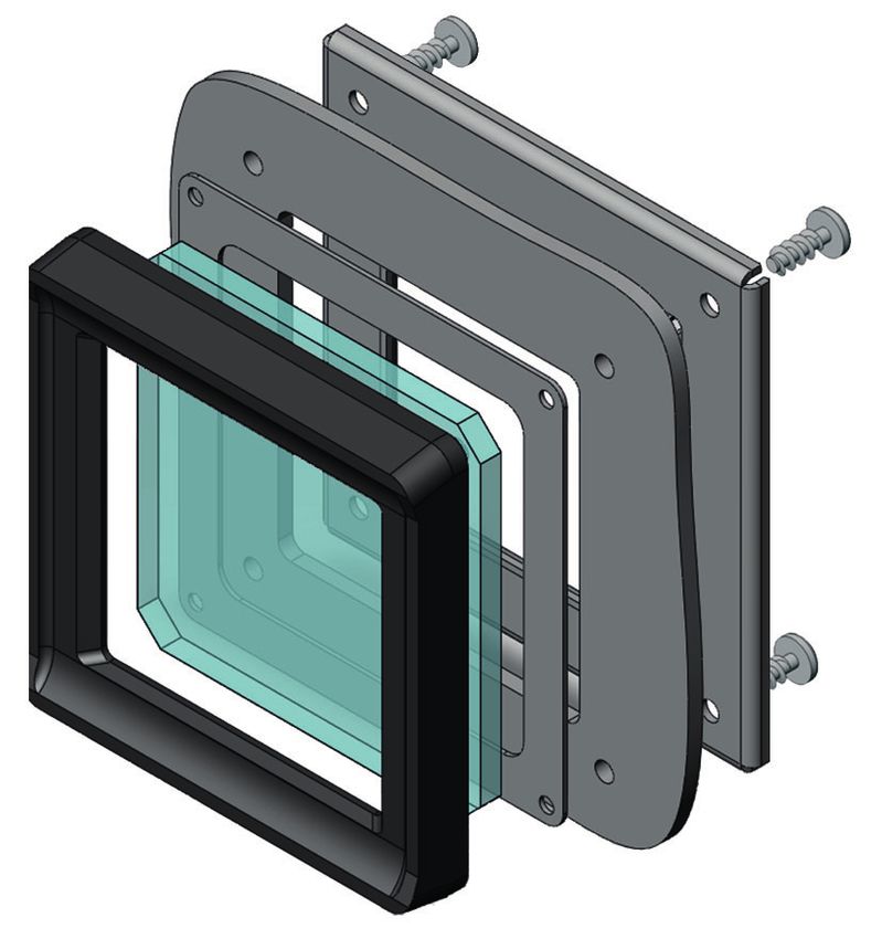
Betriebsanleitung

             Vorsatz für Mess- und
             Anzeigegeräte

             > 8603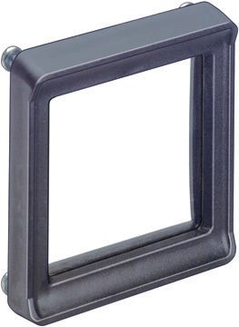
Inhaltsverzeichnis

1    Inhaltsverzeichnis
     1     Inhaltsverzeichnis ..................................................................................................2
     2     Allgemeine Angaben .............................................................................................2
     2.1   Hersteller ...............................................................................................................2
     2.2   Angaben zur Betriebsanleitung .............................................................................2
     2.3   Konformität zu Normen und Bestimmungen .........................................................2
     3     Verwendete Symbole ............................................................................................3
     4     Allgemeine Sicherheitshinweise ............................................................................3
     4.1   Aufbewahrung der Anleitung .................................................................................3
     4.2   Umbauten und Änderungen ..................................................................................4
     4.3   Sonderausführungen .............................................................................................4
     5     Bestimmungsgemäße Verwendung ......................................................................4
     6     Technische Daten .................................................................................................4
     7     Transport und Lagerung ........................................................................................4
     8     Installation .............................................................................................................5
     8.1   Maßangaben / Befestigungsmaße ........................................................................5
     9     Montage und Demontage ......................................................................................6
     10    Inbetriebnahme .....................................................................................................6
     11    Instandhaltung, Wartung und Störbeseitigung ......................................................7
     12    Reinigung ..............................................................................................................7
     13    Entsorgung ............................................................................................................7

2    Allgemeine Angaben

2.1 Hersteller
     R. STAHL Schaltgeräte GmbH
     Am Bahnhof 30
     74638 Waldenburg
     Germany

     Tel.:        +49 7942 943-0
     Fax:         +49 7942 943-4333
     Internet:    r-stahl.com

2.2 Angaben zur Betriebsanleitung
     ID-Nr.                                               155937 / 8603601300
     Publikationsnummer:                                  2021-01-25·BA00·III·de·05

2.3 Konformität zu Normen und Bestimmungen
     Die Konformität zu Normen und Bestimmungen kann den entsprechenden Zertifikaten
     und der Herstellererklärung (z. B. EG-Konformitätserklärung) entnommen werden.
     Diese Dokumente können unter r-stahl.com abgerufen werden.

2          Vorsatz für Mess- und                                                                         155937 / 8603601300
           Anzeigegeräte 8603                                                                        2021-01-25·BA00·III·de·05
Verwendete Symbole
3 Verwendete Symbole
Sicherheitshinweise
Nichtbeachtung kann zu Sachschäden, schweren Verletzungen oder
zum Tod führen.
Die Sicherheitshinweise dieser Betriebsanleitung und auf dem Gerät sind
unbedingt zu beachten!
Warnzeichen
Gefahr durch explosionsfähige Atmosphäre!
Warnzeichen
Gefahr durch spannungsführende Teile!
Hinweis
Diese Grafik kennzeichnet wichtige Zusatzinformationen, Tipps und
Empfehlungen.
4 Allgemeine Sicherheitshinweise
4.1 Aufbewahrung der Anleitung
Die Betriebsanleitung ist sorgfältig zu lesen und am Geräteeinbauort aufzubewahren.
Für den ordnungsgemäßen Betrieb sind alle der Lieferung beigelegten Dokumente sowie
die Betriebsanleitungen der anzuschließenden Geräte zu beachten.
WARNUNG
Geräte nur für den zugelassenen Einsatzzweck verwenden!
Für Schäden, die durch fehlerhaften oder unzulässigen Einsatz sowie durch
Nichtbeachtung dieser Betriebsanleitung entstehen, übernehmen wir keine
Haftung.
Das Gerät darf nur im unbeschädigten Zustand betrieben werden.
WARNUNG
Kein unbefugtes Arbeiten am Gerät!
Installation, Instandhaltung, Wartung und Störbeseitigung darf nur von dazu
befugtem und entsprechend geschultem Personal durchgeführt werden.
Beachten Sie Folgendes bei Installation und Betrieb:
Beschädigungen können den Explosionsschutz aufheben
Nationale und örtliche Sicherheitsvorschriften
Nationale und örtliche Unfallverhütungsvorschriften
Nationale und örtliche Montage- und Errichtungsvorschriften
Allgemein anerkannte Regeln der Technik
Sicherheitshinweise dieser Betriebsanleitung
Kennwerte und Bemessungsbetriebsbedingungen der Typ- und Datenschilder
Zusätzliche Hinweisschilder auf dem Gerät
155937 / 8603601300 Vorsatz für Mess- und 3
2021-01-25·BA00·III·de·05 Anzeigegeräte 8603Bestimmungsgemäße Verwendung
4.2 Umbauten und Änderungen
WARNUNG
Umbauten und Änderungen am Gerät sind nicht zulässig.
Für Schäden, die durch Umbauten und Änderungen entstehen, übernehmen
wir weder Haftung noch Gewährleistungsverpflichtungen.
4.3 Sonderausführungen
Sonderausführungen können bei zusätzlichen/abweichenden Bestelloptionen von den
hier beschriebenen Darstellungen abweichen.
5 Bestimmungsgemäße Verwendung
Der Vorsatz dient zum Einbau in Gehäusedeckel und Gehäusewände der Zündschutzart
Erhöhte Sicherheit „e“ gemäß
IEC/EN 60079-0
IEC/EN 60079-7
IEC/EN 60079-31
6 Technische Daten
Ausführung 8603
Explosionsschutz
Global (IECEx)
Gas und Staub IECEx PTB 06.0083 U
Ex eb IIC Gb
Ex tb IIIC Db
Europa (ATEX)
Gas und Staub PTB 00 ATEX 3106 U
E II 2 G Ex eb IIC Gb
E II 2 D Ex tb IIIC Db
Umgebungstemperatur -60 ... +76 °C
Material
Rahmen Polyamid
Schauscheibe Glas
Anzugsdrehmoment Befestigungsschrauben: 1,2 Nm
Schutzart IP66 gem. IEC/EN 60529
7 Transport und Lagerung
Transport und Lagerung sind nur in Originalverpackung gestattet.
Die Geräte sind trocken und erschütterungsfrei zu lagern.
4 Vorsatz für Mess- und 155937 / 8603601300
Anzeigegeräte 8603 2021-01-25·BA00·III·de·05Installation
8 Installation
8.1 Maßangaben / Befestigungsmaße
Maßzeichnungen (alle Maße in mm [Zoll]) – Änderungen vorbehalten
12 [0,47]
38 [1,50]
46 [1,81]
55 [2,17] 38 [1,50]
42 [1,65]
64 [2,52]
42 [1,65]
55 [2,17]
46 [1,81] Ø 4,50 [Ø 0,18]
64 [2,52]
04654E00 05968E00
8603/11 Öffnungsbild
12 [0,47]
62 [2,44]
62 [2,44]
55 [2,17]
2]
,1
[0
R3
50 [1,97]
62 [2,44]
72 [2,83]
55 [2,17]
62 [2,44]
Ø 4,50 [Ø 0,18]
54 [2,13]
72 [2,83]
05969E00
04655E00
8603/21 Öffnungsbild
14 [0,55]
85 [3,35]
85 [3,35]
73 [2,78]
105 [4,13]
2]
,1
[0
R3
95 [3,74]
85 [3,55]
73 [2,87]
85 [3,35]
68 [2,68]
Ø 4,50 [Ø 0,18]
68 [2,68]
95 [3,74] 4,75 [0,19]
05948E00
105 [4,13]
04658E00
8603/31 Öffnungsbild
155937 / 8603601300 Vorsatz für Mess- und 5
2021-01-25·BA00·III·de·05 Anzeigegeräte 8603Montage und Demontage
Maßzeichnungen (alle Maße in mm [Zoll]) – Änderungen vorbehalten
13 [0,51]
112 [4,41]
112 [4,41]
100 [3,94]
4]
,0
45 [1,77]
[0
56 [2,20]
44 [1,73]
66 [2,60]
R1
56 [2,20]
Ø 4,50 [Ø 0,18]
100 [3,94]
122 [4,80]
04660E00 05970E00
8603/41 Öffnungsbild
HINWEIS
Die empfohlene Dicke der Gehäusewände, in welche die Vorsätze eingebaut
werden können, liegt im Bereich von 1,5 mm bis 4 mm.
9 Montage und Demontage
Hinweis
1) nur Ausführung 8603/31
1
05854E00
Vorsatz auf Gehäusedeckel mit passenden Ausstanzungen setzen.
Die Dichtung muss plan zwischen Deckelaußenseite und Rahmen liegen.
Befestigungsschrauben mit vorgegebenem Anzugsdrehmoment (1,2 Nm) anziehen.
10 Inbetriebnahme
Stellen Sie vor der Inbetriebnahme sicher, dass
keine Komponenten beschädigt sind
das Gerät vorschriftsmäßig installiert ist
sich keine Fremdkörper im Gerät befinden
alle lösbaren Verbindungen fest angezogen sind
die vorgeschriebenen Anzugsdrehmomente eingehalten sind
die Auflageflächen für die Vorsätze plan sind
6 Vorsatz für Mess- und 155937 / 8603601300
Anzeigegeräte 8603 2021-01-25·BA00·III·de·05Instandhaltung, Wartung und Störbeseitigung
11 Instandhaltung, Wartung und Störbeseitigung
Die Art und der Umfang der Prüfungen ist den entsprechenden nationalen Vorschriften
zu entnehmen. Die Fristen sind so zu bemessen, dass entstehende Mängel, mit denen
gerechnet werden muss, rechtzeitig festgestellt werden.
WARNUNG
Gefahr durch Stromschlag!
Vor dem Öffnen des Gerätes Spannungsversorgung unterbrechen.
Überprüfen Sie bei der Wartung folgende Punkte:
fester Sitz der Leitungen
Einhaltung der zulässigen Temperaturen (gemäß IEC/EN 60079)
Beschädigungen am Gehäuse und an den Dichtungen
lösbare Verbindungen, z. B. Schrauben auf festen Sitz
fester Sitz des Vorsatzes
12 Reinigung
Das Gerät darf nur mit einem feuchtem Tuch gereinigt werden.
13 Entsorgung
Beachten Sie die nationalen Vorschriften zur Abfallbeseitigung.
155937 / 8603601300 Vorsatz für Mess- und 7
2021-01-25·BA00·III·de·05 Anzeigegeräte 8603Operating Instructions
Bezel for Measuring
Instruments and
Indicating Devices
> 8603Contents
1 Contents
1 Contents ................................................................................................................2
2 General Information ...............................................................................................2
2.1 Manufacturer .........................................................................................................2
2.2 Operating Instructions Information ........................................................................2
2.3 Conformity to Standards and Regulations .............................................................2
3 Symbols Used .......................................................................................................3
4 General Safety Instructions ...................................................................................3
4.1 Operating Instructions Storage ..............................................................................3
4.2 Alterations and Modifications ................................................................................4
4.3 Special Versions ....................................................................................................4
5 Intended Use .........................................................................................................4
6 Technical Data ......................................................................................................4
7 Transport and Storage ..........................................................................................4
8 Installation .............................................................................................................5
8.1 Dimensions / Mounting Dimensions ......................................................................5
9 Mounting and Dismounting ....................................................................................6
10 Putting into Service ...............................................................................................6
11 Maintenance, Overhaul and Repair .......................................................................7
12 Cleaning ................................................................................................................7
13 Disposal .................................................................................................................7
2 General Information
2.1 Manufacturer
R. STAHL Schaltgeräte GmbH
Am Bahnhof 30
74638 Waldenburg
Germany
Tel.: +49 7942 943-0
Fax: +49 7942 943-4333
Internet: r-stahl.com
2.2 Operating Instructions Information
ID-No.: 155937 / 8603601300
Publication Code: 2021-01-25·BA00·III·en·05
2.3 Conformity to Standards and Regulations
The conformity to the standards and regulations is specified in the corresponding
certificates and declarations of the manufacturer (e.g. EC Declaration of Conformity).
These documents are available for download on the internet page r-stahl.com.
2 Bezel for Measuring Instruments 155937 / 8603601300
and Indicating Devices 8603 2021-01-25·BA00·III·en·05Symbols Used
3 Symbols Used
Safety instructions
Non-observance can result in damage to equipment, serious injuries or
death.
The safety instructions contained in these operating instructions and affixed
to the device must be observed!
Warning symbol
Danger due to explosive atmosphere!
Warning symbol
Danger due to live parts!
Notice
This graphic marks important additional information, tips and
recommendations.
4 General Safety Instructions
4.1 Operating Instructions Storage
Read these operating instructions carefully and store them near the installation place. For
correct operation, please observe all other documents enclosed in this delivery and the
operating instructions of the equipment to be connected.
WARNING
Use the devices only for their intended purpose!
We cannot be held liable for damage caused by an incorrect or unauthorized
use or by non-observance of these operating instructions.
Use the device only if it is undamaged.
WARNING
Any unauthorized work on the device is prohibited!
Installation, maintenance, overhaul and repair may only be carried out by
appropriately authorized and trained personnel.
Observe the following information during installation and operation:
Any damage can invalidate the explosion protection
National and local safety regulations
National and local accident prevention regulations
National and local assembly and installation regulations
Generally recognized technical regulations
Safety instructions in these operating instructions
Characteristic values and rated operating conditions on the rating and data plates
Additional instruction plates fixed directly to the device
155937 / 8603601300 Bezel for Measuring Instruments 3
2021-01-25·BA00·III·en·05 and Indicating Devices 8603Intended Use
4.2 Alterations and Modifications
WARNING
Alterations and modifications to the device are not permitted.
We shall not accept any liability or warranty obligations for damage resulting
from alterations and modifications.
4.3 Special Versions
In case of additional/different order options, special versions may differ from the
description given here.
5 Intended Use
The bezel is used for installation in enclosure covers and enclosure walls of type of
protection increased safety "e" according to
IEC/EN 60079-0
IEC/EN 60079-7
IEC/EN 60079-31
6 Technical Data
Version 8603
Explosion protection
Global (IECEx)
Gas and dust IECEx PTB 06.0083 U
Ex eb IIC Gb
Ex tb IIIC Db
Europe (ATEX)
Gas and dust PTB 00 ATEX 3106 U
E II 2 G Ex eb IIC Gb
E II 2 D Ex tb IIIC Db
Ambient temperature -60 ... +76 °C
Material
Frame polyamide
Inspection window glass
Tightening torque fastening screws: 1.2 Nm
Degree of protection IP66 acc. to IEC/EN 60529
7 Transport and Storage
Transport and storage are permitted only in the original packaging.
The devices must be stored in a dry place and vibration-free.
4 Bezel for Measuring Instruments 155937 / 8603601300
and Indicating Devices 8603 2021-01-25·BA00·III·en·05Installation
8 Installation
8.1 Dimensions / Mounting Dimensions
Dimensional drawings (all dimensions in mm [inches]) – Subject to modification
12 [0,47]
38 [1,50]
46 [1,81]
55 [2,17] 38 [1,50]
42 [1,65]
64 [2,52]
42 [1,65]
55 [2,17]
46 [1,81] Ø 4,50 [Ø 0,18]
64 [2,52]
04654E00 05968E00
8603/11 Opening figure
12 [0,47]
62 [2,44]
62 [2,44]
55 [2,17]
2]
,1
[0
R3
50 [1,97]
62 [2,44]
72 [2,83]
55 [2,17]
62 [2,44]
Ø 4,50 [Ø 0,18]
54 [2,13]
72 [2,83]
05969E00
04655E00
8603/21 Opening figure
14 [0,55]
85 [3,35]
85 [3,35]
73 [2,78]
105 [4,13]
2]
,1
[0
R3
95 [3,74]
85 [3,55]
73 [2,87]
85 [3,35]
68 [2,68]
Ø 4,50 [Ø 0,18]
68 [2,68]
95 [3,74] 4,75 [0,19]
05948E00
105 [4,13]
04658E00
8603/31 Opening figure
155937 / 8603601300 Bezel for Measuring Instruments 5
2021-01-25·BA00·III·en·05 and Indicating Devices 8603Mounting and Dismounting
Dimensional drawings (all dimensions in mm [inches]) – Subject to modification
13 [0,51]
112 [4,41]
112 [4,41]
100 [3,94]
4]
,0
45 [1,77]
[0
56 [2,20]
44 [1,73]
66 [2,60]
R1
56 [2,20]
Ø 4,50 [Ø 0,18]
100 [3,94]
122 [4,80]
04660E00 05970E00
8603/41 Opening figure
NOTE
The recommended thickness of the enclosure walls into which the bezels are
built ranges from 1.5 mm to 4 mm.
9 Mounting and Dismounting
Notice
1) version 8603/31 only
1
05854E00
Place the bezel with suitable cutouts on the enclosure cover.
The seal must lie flat between the cover exterior and the frame.
Tighten the fastening screws to the specified tightening torque (1.2 Nm).
10 Putting into Service
Before putting into service, ensure that
no components are damaged
the device has been installed according to regulations
there are no foreign bodies inside the device
all screws and nuts have been firmly tightened
the prescribed tightening torques have been observed
the bearing surfaces for the attachments are flat
6 Bezel for Measuring Instruments 155937 / 8603601300
and Indicating Devices 8603 2021-01-25·BA00·III·en·05Maintenance, Overhaul and Repair
11 Maintenance, Overhaul and Repair
Consult the relevant national regulations to determine the type and extent of inspections.
Plan the intervals such that any defects in the equipment which may be anticipated are
promptly detected.
WARNING
Risk of electric shock!
Before opening the device, disconnect it from the power supply.
The following details must be checked during maintenance:
Cables are held securely in place
Compliance with the permitted temperatures (according to IEC/EN 60079)
Damage to the enclosure and seals
Check if screws and nuts are tight.
12 Cleaning
The device may only be cleaned with a damp cloth.
13 Disposal
Observe the national waste disposal regulations.
155937 / 8603601300 Bezel for Measuring Instruments 7
2021-01-25·BA00·III·en·05 and Indicating Devices 8603Sie können auch lesen