CLS FUSION - 7 Ah CLS FUSION - 10/12/24 Ah - Notlichtversorgungsgerät - INOTEC ...
←
→
Transkription von Seiteninhalten
Wenn Ihr Browser die Seite nicht korrekt rendert, bitte, lesen Sie den Inhalt der Seite unten
Mounting- and Operating Instructions   Montage- und Betriebsanleitung

Emergency Lighting Device              Notlichtversorgungsgerät
CLS FUSION - 7 Ah                      CLS FUSION - 7 Ah
CLS FUSION - 10/12/24 Ah               CLS FUSION - 10/12/24 Ah
CLS FUSION - Power - 20/24/48 Ah       CLS FUSION - Power - 20/24/48 Ah

                                                               Sicherheitstechnik GmbH
                                                                                    1
CLS FUSION Montage- und Betriebsanleitung   CLS FUSION Mounting and Operating Instructions

    Montage- und Betriebsanleitung           Mounting- and Operating Instructions

    Notlichtversorgungsgerät                 Emergency Lighting Device
    CLS FUSION - 7 Ah                        CLS FUSION - 7 Ah
    CLS FUSION - 10/12/24 Ah                 CLS FUSION - 10/12/24 Ah
    CLS FUSION - Power - 20/24/48 Ah         CLS FUSION - Power - 20/24/48 Ah

                                                                                             3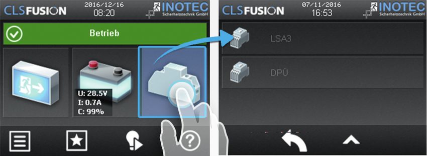
CLS FUSION Montage- und Betriebsanleitung CLS FUSION Mounting and Operating Instructions
Inhalt Contents
1. Allgemeine Hinweise 5 1. General information 5
1.1. Symbolerklärung 5 1.1. Explanation of symbols 5
1.2. Haftung und Gewährleistung 5 1.2. Liability and warranty 5
1.3. Ersatzteile 5 1.3. Spare parts 5
1.4. Entsorgung 5 1.4. Disposal5
1.5. Fehlerbeseitigung 5 1.5. Correction of faults 5
2. Sicherheitshinweise 6 2. Safety instructions 6
2.1. Bedienungsanleitung 6 2.1. Operating instructions 6
2.2. Reparaturen 6 2.2. Repairs6
3. Transport und Lagerung 6 3. Transport and storage 6
3.1. Kontrolle bei Anlieferung 6 3.1. Examination on delivery 6
3.2. Lagerung 6 3.2. Storage 6
4. Produktbeschreibung 7 4. Product description 7
4.1. Aufbau der CLS-Geräte 9 4.1. Design and structure of CLS devices 9
5. Technische Daten 11 5. Technical data 11
5.1. CLS FUSION - 7 Ah 11 5.1. CLS FUSION - 7 Ah 11
5.2. CLS FUSION - 10 Ah 12 5.2. CLS FUSION - 10 Ah 12
5.3. CLS FUSION - 12 Ah / 24 Ah 13 5.3. CLS FUSION - 12 Ah / 24 Ah 13
5.4. CLS FUSION - Power - 20 Ah 14 5.4. CLS FUSION - Power - 20 Ah 14
5.5. FUSION - Power - 24 / 48 Ah 15 5.5. CLS FUSION - Power - 24 / 48 Ah 15
6. Montage 16 6. Mounting16
6.1. Gerät 16 6.1. Device16
6.2. Batterie 17 6.2. Battery17
6.3. Elektrischer Anschluss 19 6.3. Electrical connection 19
7. Inbetriebnahme des CLS-Gerätes 42 7. Commissioning the CLS device 42
7.1. Ausschalten des CLS-Gerätes 42 7.1. Switching OFF the CLS device 42
8. TFT Steuerteil Touchdisplay 44 8. TFT Steuerteil Touchdisplay 44
8.1. Allgemeines 44 8.1. General Information 44
8.2. Begrifflichkeiten 45 8.2. Concepts45
8.3. Bedienung 49 8.3. Operation49
8.4. Hauptmenü 49 8.4. Main menu 49
9. Menüleiste 66 9. Menu bar 66
9.1. Menüstruktur 66 9.1. Menu structure 66
9.2. Menü 67 9.2. Menu67
9.3. Programmierung 85 9.3. Programming85
9.4. Return Button 85 9.4. Return Button 85
9.5. Scrollen 85 9.5. Scrollen85
9.6. Softwarestand 85 9.6. Software version 85
10. INOWeb 85 10. INOWeb85
11. Prüfungen 86 11. Tests 86
11.1. Erstprüfungen 86 11.1. Initial tests 86
11.2. Wiederkehrende Prüfungen der elektrischen Anla- 11.2. Recurring safety tests on electrical systems 86
gen für Sicherheitszwecke 86 11.3. Battery inspection and monitoring 88
11.3. Batterieinspektion und –überwachung 88 11.4. Protocols for repeat tests 88
11.4. Protokolle zu wiederkehrenden Prüfungen 88
4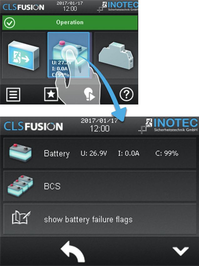
CLS FUSION Montage- und Betriebsanleitung CLS FUSION Mounting and Operating Instructions
1. Allgemeine Hinweise 1. General information
1.1. Symbolerklärung 1.1. Explanation of symbols
Sicherheitsrelevante Informationen sind durch This symbol highlights important information
nebenstehendes Symbol gekennzeichnet. Eine in the mounting and operating instructions that
Nichtbefolgung der Anweisungen kann zu Per- also concerns safety. Failure to follow the instruc-
sonenschäden oder defektem Gerät führen! tions may result in personal injury or breakage!
Hinweise liefern wichtige Informationen und Instructions marked by a yellow icon provide
sind mit einem gelben Symbol markiert. Bitte important information. Please read this very
lesen Sie diese sehr aufmerksam. carefully.
Dieses Symbol macht Sie auf zusätzliche Infor- This icon provides additional information.
mationen aufmerksam.
1.2. Haftung und Gewährleistung 1.2. Liability and warranty
INOTEC übernimmt keine Gewährleistung oder Haftung INOTEC does not accept any responsibility or liability
für Schäden oder Folgeschäden, die entstehen durch whatsoever for damage or consequential damage
• Nicht bestimmungsgemäßen Gebrauch caused by:
• Nichteinhaltung von Vorschriften für den sicheren • failure to operate devices according to their
Betrieb intended use
• Betrieb von nicht zugelassenen oder ungeeigneten • failure to follow instructions relating to safe operation
Komponenten am Notlichtsystem • the use of unauthorized or unsuitable components
• Bei fehlerhafter Installation in conjunction with the emergency lighting system
• Bei Eingriff in das Gerät • faulty installation
• opening the device
1.3. Ersatzteile
Defekte Bauteile dürfen nur gegen INOTEC-Original- 1.3. Spare parts
Ersatzteile ausgetauscht werden. Nur bei diesen Teilen Defective components must only be replaced with origi-
gewährleisten wir, dass Sie die Sicherheitsanforderungen nal INOTEC spare parts. We cannot guarantee that safety
im vollen Umfang erfüllen. Garantie-, Service- und Haft- requirements are fully met if parts other than these are
pflichtansprüche erlöschen bei Verwendung nicht geeig- used. No warranty, service or liability claims
neter Ersatzteile. will be acknowledged if unsuitable spare parts are used.
Der Einsatz von fehlerhaften Ersatzteilen kann zu
fehlerhaftem Betrieb oder einem nicht funktio- The use of defective spare parts may result in mal-
nierendem System führen. function or cause the system the fail entirely.
1.4. Entsorgung
Von INOTEC gelieferte Batterien und Elektronikbauteile 1.4. Disposal
können an INOTEC zurückgegeben werden oder sind Batteries and electronic components supplied by INO-
gemäß den nationalen Richtlinien und Vorschriften für TEC can be returned to INOTEC, or should be disposed of
die Entsorgung von Alt-Batterien und Elektronikbautei- in accordance with the national guidelines and regula-
len zu entsorgen. tions governing the disposal of used batteries and elec-
tronic components.
1.5. Fehlerbeseitigung
Nach jeder Fehlerbeseitigung der angeschlosse- 1.5. Correction of faults
nen Leuchten muss ein Funktionstest ausgelöst Whenever a fault associated with connected lumi-
werden, um den angezeigten Fehler zu löschen. naires is corrected, a function test must be carried
9.2.1.1. Funktionstest (FT) starten - Seite 68 out to reset the fault indication.
9.2.1.1. Start function test (FT) - page 68
5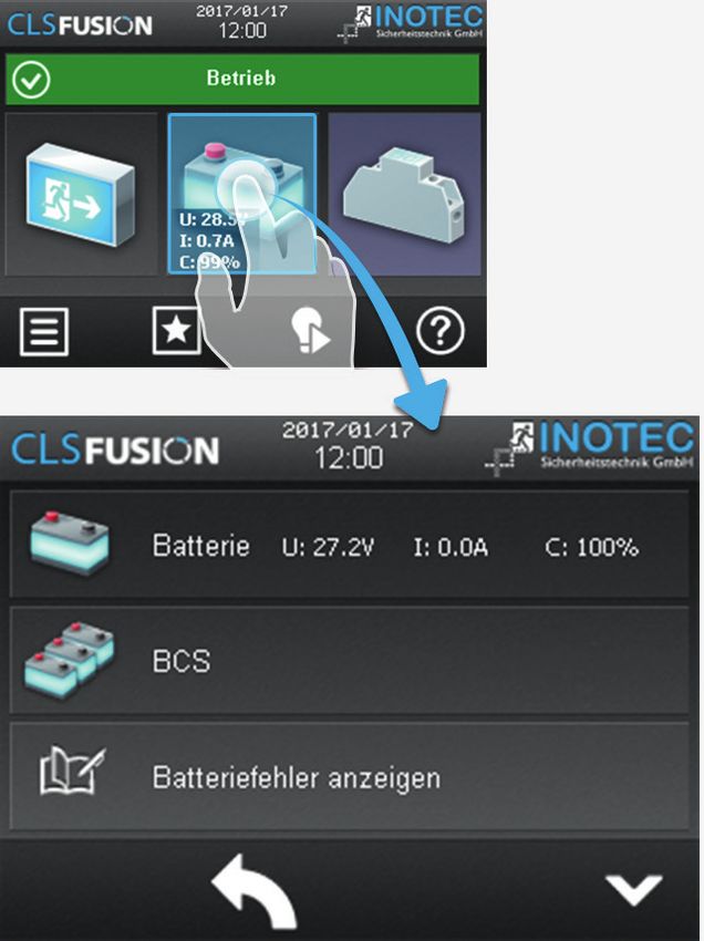
CLS FUSION Montage- und Betriebsanleitung CLS FUSION Mounting and Operating Instructions
2. Sicherheitshinweise 2. Safety instructions
Die Installation darf nur durch Elektrofachkräfte Installation should only be carried out by electri-
erfolgen. cians qualified and trained.
Das Gerät ist bestimmungsgemäß und nur im einwand- The device must not be used for anything other than its
freien, unbeschädigten Zustand zu betreiben. intended purpose and only in a perfect and undamaged
Für die Installation und den Betrieb dieses Gerätes sind condition.When installing and operating this device,
die nationalen Sicherheits- und Unfallverhütungsvor- please follow your national safety and accident preven-
schriften zu beachten. tion regulations at all times.
Vor Arbeiten an dem Gerät, insbesondere beim Aus- Before carrying out any work on the device, in particular
tausch von Baugruppen, ist die Anlage spannungsfrei zu when replacing components, always disconnect the
schalten (Netz- und Batteriespannung)! system from the power source (mains and battery).
7.1. Ausschalten des CLS-Gerätes - Seite 42 7.1. Switching OFF the CLS device - page 42
Elektrische Bauteile, wie LEDs, sind Electrical components (e.g. LEDs)
empfindlich gegen elektrostati- are sensitive to electrostatic
sche Entladung und können discharge(ESD) and can already be
bereits beim Berühren der destroyed when touching the ter-
Anschlüsse zerstört werden. Für die Montage sind geeig- minals. Please observe suitable ESD protective measures
nete ESD-Schutzmaßnahmen zu treffen! while mounting.
2.1. Bedienungsanleitung 2.1. Operating instructions
Lesen Sie vor der Montage- und Inbetriebnahme Always read the mounting and operating instruc-
die Montage- und Betriebsanleitung. Sie gibt tions before installing and commissioning the
wichtige Informationen für die Sicherheit, den device. These instructions contain important
Gebrauch und die Wartung des Gerätes. Dadurch schüt- information on the safety, use and maintenance of the
zen Sie sich und verhindern Schäden am Gerät. device, and will protect you and prevent damage to the
system.
2.2. Reparaturen
Eventuelle Reparaturen oder Eingriffe dürfen ausschließ- 2.2. Repairs
lich durch INOTEC autorisierte Personen vorgenommen Any repairs which need to be carried out or which
werden. involve opening the device must ONLY be carried out
by personnel authorized to do so by INOTEC.
3. Transport und Lagerung 3. Transport and storage
3.1. Kontrolle bei Anlieferung 3.1. Examination on delivery
Überprüfen Sie das Gerät bei Anlieferung unverzüglich Please examine the device carefully at point of receipt
auf Vollständigkeit und äußere Beschädigungen. Mel- to ensure complete delivery and that no external dam-
den Sie dem Spediteur offensichtliche Beschädigungen age exists. Please inform the carrier immediately if there
sofort, da wir spätere Reklamationen nicht anerkennen. are any signs of damage — we regret that we are unable
to acknowledge complaints submitted after this point.
3.2. Lagerung
Das Gerät ist bis zur Montage wie folgt zu lagern: 3.2. Storage
• Nicht im Freien aufbewahren Until assembly, please observe the following regarding
• Trocken und staubfrei lagern storage of the device:
• Do not store in the open air
Für die eingebauten Batterien gilt: • Do store in a dry, dust-free environment
• Batterien dürfen max. 3 Monate ohne Ladung gelagert The following applies to batteries that have already
werden been fitted:
• Bei längerer Unterbrechung der Netzversorgung muss • Batteries must not be stored for more than 3 months
der Batteriekreis durch Entfernen der Batteriesicherung without being charged
gemäß Betriebsanleitung freigeschaltet werden • If the mains supply is interrupted for an extended
• Vor der ersten Funktionsprüfung sind die Batterien min. period of time, the battery circuit must be disconnected
24 Stunden zu laden by removing the battery fuse in accordance with the
operating instructions –
• Charge the batteries for at least 24 hours before carrying
out the initial function test
6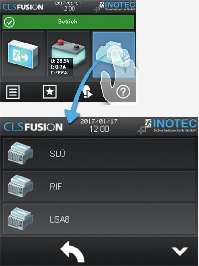
CLS FUSION Montage- und Betriebsanleitung                    CLS FUSION Mounting and Operating Instructions

4. Produktbeschreibung                                       4. Product description
 Die dezentrale INOTEC Notlichtanlage CLS FUSION ist ein      The CLS local INOTEC emergency lighting system is
 Versorgungsgerät für den Betrieb und die Überwachung         a protection class I supply device for using and monito-
 von bis zu 160 Sicherheits- und Rettungszeichenleuch-        ring up to 160 safety and emergency exit luminaires. Up
 ten in Schutzklasse III (SELV). Je Abgang können bis zu      to 20 luminaires in different switch modes can be opera-
 20 Leuchten in 5 unterschiedlichen Schaltungsarten           ted per output.
 betrieben werden.
                                                              The CLS FUSION System includes:
 Das CLS FUSION System beinhaltet:                            • Battery for 1 hr, 3 hrs or 8hrs emergency lighting mode
 • Batterie für 1 Std., 3 Std. oder 8 Std. Notlichtbetrieb    • Maximum of 8 circuit outputs, suitable for up to 20
 • max. 8 Stromkreisabgänge, geeignet für bis zu 20             luminaires with a maximum connected current of 3A
   Leuchten mit einem maximalen Anschlussstrom von 3A           per circuit (CLS FUSION and CLS FUSION - Power)
   je Stromkreis (CLS FUSION und CLS FUSION - Power)          • Maximum of 4 circuit outputs, suitable for up to 20
 • max. 4 Stromkreisabgänge, geeignet für bis zu 20             luminaires with a maximum connected current of 3A
   Leuchten mit einem maximalen Anschlussstrom von 3A           per circuit (CLS FUSION - 7 Ah)
   je Stromkreis (CLS FUSION - 7 Ah)                          • Integrated TFT controller for status information
 • Integriertes TFT touch Steuerteil für                      • Integrated network module to connect INOWeb and
   Statusinformationen                                          INOView
 • Integriertes Netzwerkmodul zur Anbindung an INOWeb         • Integrated 8-channel light switch query
   und INOView                                                • Log book
 • integrierte 8-kanalige Lichtschalterabfrage                • Individual LED monitoring
 • Prüfbuch                                                   • Battery-Control-System
 • Einzel-LED Überwachung                                     • To connect to dynamic escape route lighting (D.E.R.)
 • Battery-Control-System
 • zur Anbindung von dynamischen                              The luminaires get supplied by a 2-core supply line with
   Rettungszeichenleuchten (D.E.R.)                           24V-protective low voltage and can be programmed
                                                              via the configurator. Thereby a logical link with a circuit
 Die Leuchten werden über eine zweiadrige Versorgungs-        address gets allocated to a specific luminaire address.
 leitung mit 24V-Schutzkleinspannung versorgt und kön-
 nen über den Konfigurator programmiert werden. Dabei         The emergency lighting system identifies the LED failure
 wird der eindeutigen Leuchtenadresse eine logische           types short circuit and interruption at the individual
 Verknüpfung mit einer Stromkreisadresse zugewiesen.          luminaires. Every failure of a single LED gets reported.

 Das Notlichtsystem erkennt die LED-Fehlerarten Kur-          The freely programmable TFT controller has several
 zschluss oder Unterbrechung in der einzelnen Leuchte.        function panels and a display to visualise the device and
 Jeder Ausfall einer einzelnen LED wird gemeldet.             luminaire status. All information required according to
                                                              DIN EN 50171 are displayed in the main monitor. This
 Das frei programmierbare TFT Steuerteil hat mehrere          also includes operation status of the emergency lighting
 Funktionsschaltflächen und eine Anzeige zur Visual-          system, battery voltage, battery charging and discharg-
 isierung des Geräte- bzw. Leuchtenstatus. Alle nach DIN      ing current, battery capacity. The status of luminaire
 EN 50171 geforderten Informationen werden im Haupt-          can be called up on the display. Additional information
 bild angezeigt. Dazu zählen Betriebsstatus des Notli-        concerning network failure UV, deep discharge protec-
 chtsystems, Batteriespannung, Batterielade- oder -ent-       tion, manual resetting, follow-up emergency lighting or
 ladestrom, Batteriekapazität. Zu jeder einzelnen Leuchte     the status of external modules get also displayed. Via the
 kann der Zustand am Display abgerufen werden. Weiter-        USB interface integrated as standard text information for
 hin werden Informationen zum Netzausfall UV, Tiefentla-      the individual luminaires can be deposited or configura-
 deschutz, Handrückschaltung, nachlaufendem Notlicht          tion can be played on.
 oder der Status der externen Module angezeigt. Über die
 serienmäßig integrierte USB-Schnittstelle können Tex-        The triggering of the dynamic emergency light-
 tinformation zu den einzelnen Leuchten hinterlegt oder       ing device is supported as standard. For every single
 Konfigurationen aufgespielt werden.                          dynamic emergency lighting luminaire up to 8 controller
                                                              inputs can be assigned. The following settings are pos-
 Die Ansteuerung von dynamischen Rettungszeichen-             sible and can also be combined: arrow down or arrow
 leuchten wird standardmäßig unterstützt. Jeder einzel-       up, arrow right, arrow left, cross (blocked) pictogram
 nen dynamischen Rettungszeichenleuchte können bis            on/off and flashing function. An update later on for the
 zu 8 Steuereingänge zugewiesen werden. Folgende Ein-         dynamic escape sign luminaires is possible.
 stellungen werden unterstützt und können kombiniert
 werden: Pfeil unten oder Pfeil oben, Pfeil rechts, Pfeil
 links, Kreuz (gesperrt), Piktogramm ein/aus und Blink-
 funktion. Eine spätere Nachrüstmöglichkeit für dynamis-
 che Rettungszeichenleuchten ist ohne weiteres möglich.

                                                                                                                            7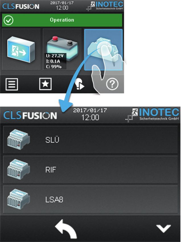
CLS FUSION Montage- und Betriebsanleitung CLS FUSION Mounting and Operating Instructions
Die nach DIN EN 62034 geforderten Tests sind integriert The tests required according to DIN EN 62034 are inte-
und können individuell angepasst werden. Das Notlicht- grated and can be adjusted individually. The emergency
system führt diese nach dem vorgegebenen Intervall aus lighting system executes them after the fixed interval
und speichert die Ergebnisse im integrierten Prüfbuch and saves the results in the integrated logbook, which
mit einem Fassungsvermögen von mehr als 2.000 Einträ- has capacity for more than 2.000 entries. The results
gen. Die Ergebnisse des Batterie-Überwachungssystems of the battery monitoring system with individual block
mit Einzelblocküberwachung werden in einem sepa- monitoring gets saved in a separate log book.
raten Prüfbuch gespeichert.
There are five voltfree contacts for the external failure
Fünf potentialfreie Kontakte zur externen Fehlermel- notification/status display. Two of them can be pro-
dung/Statusanzeige sind vorhanden. Zwei dieser Kon- grammed freely.
takte sind frei programmierbar.
The status can be called up within the whole network
Über das integrierte Netzwerkmodul kann der Zustand via webbrowser with the integrated network module.
überall im Netzwerk per Webbrowser abgerufen The access on the HTML-page can be protected with a
werden. Der Zugriff auf die HTML-Seiten ist über ein frei freely choosable password. The CLS FUSION System can
wählbares Passwort zu schützen. Über das Netzwerk be monitored via the network module with the INOTEC
modul kann das CLS FUSION System mittels INOTEC Software “INOView”.
Software “INOView” überwacht werden.
Unterverteiler der Allgemeinbeleuchtung
Netz / Verteiler der Allgemeinbeleuchtung sub-distributor of the general lighting
Mains / distribution of the general lighting 3 L/N/PE
L/N/PE
max. 500m 1,5mm² DPÜ/B
LSA 8.1
Optional LSA.3 CLS Dimmer
max.2 max.8 max.31 max.1
3 3
2 Stromschleife DPÜ
Current Loop
max. 2000m 1,5mm² Pot. Meldekontakte für GLT
CLS-MTB
Volt-free signalling cotacts for GLT
CLS Mimic panel
oder / or
Fermeldetableau
Störung
Failure
Batt.-Betrieb
RTG
Bat.-Operation
Betrieb
Operation
Mimic panel
7
Betrieb
Operation
Betrieb
Störung -Betrieb
Failure -Operation
Ein/On
max. 500m 0,5mm²
Aus/Off
INOTEC
RTG (3) oder Netzwerk
Integrierte LSA
RTG (3) or Network
Integrated LSA
RTG= max. 500m min. 0,5mm² INOWeb / INOView
2 Stromkreis 1 á 3A
Circuit 1 á 3A
Interner BUS
Internal BUS
2 Stromkreis 2 á 3A
Circuit 2 á 3A
2 Stromkreis 8 á 3A
Circuit 8 á 3A
8
CLS FUSION Montage- und Betriebsanleitung                    CLS FUSION Mounting and Operating Instructions

4.1. Aufbau der CLS-Geräte                                  4.1. Design and structure of CLS devices

    CLS FUSION - 10 Ah / 12 Ah                                                              CLS FUSION - 24 Ah

                                            Kabeleinführung / Cable inlet

                                            Kabeleinführung / Cable inlet

                                                 Klemmen / Terminals
                                               Netzsicherung / Main fuse

                                                 Steuerteil / Controller

                                            Batteriesicherung / Battery fuse

                                                  Wandler / Inverter

                                               Batteriefach / Battery case

                                                                                                                 9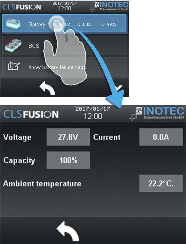
CLS FUSION Montage- und Betriebsanleitung                         CLS FUSION Mounting and Operating Instructions

     CLS FUSION - Power 20 Ah / 24 Ah                                                    CLS FUSION - Power 48 Ah
                                        Kabeleinführung / Cable inlet

                                        Klemmen / Terminals

                                        Steuerteil / Controller

                                        Batteriesicherung / Battery fuse

                                             Wandler / Inverter

                                            Batteriefach / Battery case

     CLS FUSION - 7 Ah
                                             Kabeleinführung / Cable inlet

                                             Klemmen / Terminals

                                             Steuerteil / Controller

                                             Batteriesicherung / Battery fuse

                                             Wandler / Inverter

                                             Batteriefach / Battery case

10
CLS FUSION Montage- und Betriebsanleitung CLS FUSION Mounting and Operating Instructions
5. Technische Daten 5. Technical data
5.1. CLS FUSION - 7 Ah 5.1. CLS FUSION - 7 Ah
Anschlussspannung: 230V AC +/-10% Nominal voltage: 230V AC +/-10%
max. Eingangsstrom: 0,6A Max. Input voltage: 0.6A
Netzsicherung: 5AT, AV=1500A Mains Fuse: 5AT, IR=1500A
Ausgangsspannung: 24V DC +/-20% Output voltage: 24V DC +/-20%
Zul. Umgebungstemperatur -5°C bis +25°C Amb. temp. range: -5°C until +25°C
Endstromkreise: 2 (max.4) Final circuit: 2 (max.4)
Max. Belastung : 3A je Stromkreis Max. load: 3A per final circuit
Endstromkreissicherung: 5AT, AV=1500A Final circuit fuses: 5AT, IR=1500A
Schutzklasse: I Protection class: I
Schutzart: IP20 Protection catergory: IP20
max. Anschlussquerschnitt (mm²) für: Max. cross section (mm²) for:
Netzzuleitung: 4 Mains: 4
Lichtschalterabgänge: 4 LSA: 4
Endstromkreise: 2,5 Final circuits: 2.5
Meldekontakte: 1,5 Voltfree signalling contacts: 1.5
Gewicht: ca.10kg Weight: approx.10kg
Abmessung Dimensions
375 x 240 x 120 375 x 240 x 120
H x B x T (mm): H x W x D(mm):
Schrankvariante: Cabinet options:
Brandschutzschrank BRS40: 1198 x 648 x 449 Fire protection cabinet BRS40: 1198 x 648 x 449
Stahlblechwandschrank IP20: 800 x 400 x 210 Sheet steel wall cabinet IP20: 800 x 400 x 210
Stahlblechwandschrank IP54: 800 x 400 x 210 Sheet steel wall cabinet IP54: 800 x 400 x 210
Batterie: 24V/7,2Ah Battery: 24V/7.2Ah
Batteriesicherung: 30A, AV=1000A Battery fuse: 30A, IR=1000A
Wandlersicherung: 30A, AV=1000A Converter fuse: 30A, IR=1000A
Entnahmeströme für eine
Nennbetriebsdauer von: Battery power:
1h 3,0A 1h 3.0A
2h 2,5A 2h 2.5A
3h 1,7A 3h 1.7A
8h - 8h -
bei den Entnahmeströmen ist eine Alterungsreserve zu Battery power without aging reserve.
berücksichtigen Dimensioned drawing:
Maßbild:
7 Ah
29,5
190
200
375
240 120
11CLS FUSION Montage- und Betriebsanleitung CLS FUSION Mounting and Operating Instructions
5.2. CLS FUSION - 10 Ah 5.2. CLS FUSION - 10 Ah
Anschlussspannung: 230V AC +/-10% Nominal voltage: 230V AC +/-10%
max. Eingangsstrom: 2,2A Max. Input voltage: 2.2A
Netzsicherung: 5AT, AV=1500A Mains Fuse: 5AT, IR=1500A
Ausgangsspannung: 24V DC +/-20% Output voltage: 24V DC +/-20%
Zul. Umgebungstemperatur: 0°C bis +40°C Amb. temp. range: 0°C until +40°C
Endstromkreise: 4 (max.8) Final circuit: 4 (max.8)
Max. Belastung : 3A je Stromkreis Max. load: 3A per final circuit
Endstromkreissicherung: 5AT, AV=1500A Final circuit fuses: 5AT, IR=1500A
Schutzklasse: I Protection class: I
Schutzart: IP20 Protection catergory: IP20
max. Anschlussquerschnitt (mm²) für: Max. cross section mm² for:
Netzzuleitung: 4 Mains: 4
Lichtschalterabgänge: 4 LSA: 4
Endstromkreise: 2,5 Final circuits: 2.5
Meldekontakte: 1,5 Voltfree signalling contacts: 1.5
Gewicht: ca.15kg Weight: approx. 15kg
Abmessung: H x B x T: 510 x 280 x 146 mm Dimensions H x W x D(mm) 510 x 280 x 146 mm
Farbe: RAL 7015 Color: RAL 7015
Schrankvariante: Cabinet options:
Sheet steel wall cabinet IP20: 800 x 400 x 210
Stahlblechwandschrank IP20: 800 x 400 x 210
Sheet steel wall cabinet IP54: 800 x 400 x 210
Stahlblechwandschrank IP54: 800 x 400 x 210
HD Sheet steel wall cabinet IP66: 770 x 610 x 275
HD Wandschrank IP66: 770 x 610 x 275
Battery: 24V/10Ah
Batterie: 24V/10Ah
Battery fuse: 30A, IR=1000A
Batteriesicherung: 30A, AV=1000A
Converter fuse: 30A, IR=1000A
Wandlersicherung: 30A, AV=1000A
Entnahmeströme für eine Battery power:
Nennbetriebsdauer von:
1h 7,9A 1h 7.9A
3h 2,8A 3h 2.8A
8h 1,2A 8h 1.2A
Eine Alterungsreserve muss nicht berücksichtigt werden. Battery power with aging reserve
Maßbild: Dimensioned drawing:
10 Ah
210
60
400
510
280 146
12CLS FUSION Montage- und Betriebsanleitung CLS FUSION Mounting and Operating Instructions
5.3. CLS FUSION - 12 Ah / 24 Ah 5.3. CLS FUSION - 12 Ah / 24 Ah
Anschlussspannung: 230V AC +/-10% Nominal voltage: 230V AC +/-10%
max. Eingangsstrom: 2,2A Max. Input voltage: 2.2A
Netzsicherung: 5AT, AV=1500A Mains Fuse: 5AT, IR=1500A
Ausgangsspannung: 24V DC +/-20% Output voltage: 24V DC +/-20%
Zul. Umgebungstemperatur: -5°C bis +25°C Amb. temp. range: -5°C until +25°C
Endstromkreise: 4 (max.8) Final circuit: 4 (max.8)
Max. Belastung : 3A je Stromkreis Max. load: 3A per final circuit
Endstromkreissicherung: 5AT, AV=1500A Final circuit fuses: 5AT, IR=1500A
Schutzklasse: I Protection class: I
Schutzart: IP20 Protection catergory: IP20
max. Anschlussquerschnitt (mm²) für: Max. cross section for:
Netzzuleitung: 4 Mains: 4
Lichtschalterabgänge: 4 LSA: 4
Endstromkreise: 2,5 Final circuits: 2.5
Meldekontakte: 1,5 Voltfree signalling contacts: 1.5
12Ah Anlage 24 Ah Anlage 12Ah Device 24 Ah Device
Gewicht: ca.17kg ca.25kg Weight: approx.17kg approx.25kg
Abmessung H x B x T (mm): 510x280x146 615x280x146 Dimensions H x W x D(mm): 510x280x146 615x280x146
Schrankvariante: Cabinet options:
Brandschutzschrank BRS40: 1198 x 648 x 449 Fire protection cabinet BRS40: 1198 x 648 x 449
Stahlblechwandschrank IP20: 800 x 400 x 210 Sheet steel wall cabinet IP20: 800 x 400 x 210
Stahlblechwandschrank IP54: 800 x 400 x 210 Sheet steel wall cabinet IP54: 800 x 400 x 210
12Ah Anlage 24 Ah Anlage 12Ah Device 24 Ah Device
Batterie: 24V/12Ah 24V/24 Ah Battery: 24V/12Ah 24V/24 Ah
Batteriesicherung: 30A, AV=1000A Battery fuse: 30A, IR=1000A
Wandlersicherung: 30A, AV=1000A Converter fuse: 30A, IR=1000A
Entnahmeströme für eine
Nennbetriebsdauer von: 12Ah Anlage 24 Ah Anlage Battery power: 12Ah Device 24 Ah Device
1h 7,4A 7,0A 1h 7.4A 7.0A
2h 3,9A 7,0A 2h 3.9A 7.0A
3h 2,8A 5,9A 3h 2.8A 5.9A
8h 1,2A 2,6A 8h 1.2A 2.6A
bei den Entnahmeströmen ist eine Alterungsreserve zu Battery power without aging reserve.
berücksichtigen.
Maßbild: Dimensioned drawing:
12 Ah 24 Ah
210
210
60
60
400
400
510
500
615
280 146
280 146
13CLS FUSION Montage- und Betriebsanleitung CLS FUSION Mounting and Operating Instructions
5.4. CLS FUSION - Power - 20 Ah 5.4. CLS FUSION - Power - 20 Ah
Anschlussspannung: 230V AC +/-10% Nominal voltage: 230V AC +/-10%
max. Eingangsstrom: 3,5A max. Input current: 3.5A
Netzsicherung: 5AT, AV=1500A Mains fuse: 5AT, IR=1500A
Ausgangsspannung: 24V DC +/-20% Output voltage: 24V DC +/-20%
Zul. Umgebungstemperatur: 0°C bis +40°C Amb. temp. range: 0°C until +40°C
Geräuschpegel: 0dB (lüfterlos) Noise level: 0dB
Endstromkreise: 4 (max.8) Final circuit: 4 (max.8)
Max. Belastung : 3A je Stromkreis Max. load: 3A per final circuit
Endstromkreissicherung: 5AT, AV=1500A Final circuit fuses: 5AT, IR=1500A
Schutzklasse: I Protection class: I
Schutzart: IP20 Protection catergory: IP20
max. Anschlussquerschnitt (mm²) für: Max. cross section for:
Netzzuleitung: 4 Mains: 4
Lichtschalterabgänge: 4 LSA: 4
Endstromkreise: 2,5 Final circuits: 2.5
Meldekontakte: 1,5 Voltfree signalling contacts: 1.5
Gewicht: ca.35kg Weight: approx. 35kg
Abmessung H x B x T (mm): 800 x 400 x 210 Dimensions H x W x D(mm): 800 x 400 x 210
Farbe: RAL 7015 Color: RAL 7015
Schrankvariante: Cabinet options:
Stahlblechwandschrank IP20: 800 x 400 x 210 Sheet steel wall cabinet IP20: 800 x 400 x 210
Stahlblechwandschrank IP54: 800 x 400 x 210 Sheet steel wall cabinet IP54: 800 x 400 x 210
HD Wandschrank IP66: 770 x 610 x 275 HD Sheet steel wall cabinet IP66: 770 x 610 x 275
Batterie: 24 V / 20 Ah Battery: 24V / 20 Ah
Batteriesicherung: 30A, AV=1000A Battery fuse: 30A, IR=1000A
Wandlersicherung: 30A, AV=1000A Converter fuse: 30A, IR=1000A
Entnahmeströme für eine
Battery power:
Nennbetriebsdauer von:
1h 14,0A 1h 14,0A
3h 5,7A 3h 5,7A
8h 1,9A 8h 1,9A
Eine Alterungsreserve muss nicht berücksichtigt werden. Battery power with aging reserve
Maßbild: Dimensioned drawing:
Power - 20Ah
430
370
ø8,5 330
800
750
830
400 12 210
14CLS FUSION Montage- und Betriebsanleitung CLS FUSION Mounting and Operating Instructions
5.5. FUSION - Power - 24 / 48 Ah 5.5. CLS FUSION - Power - 24 / 48 Ah
Anschlussspannung: 230V AC +/-10% Nominal voltage: 230V AC +/-10%
max. Eingangsstrom: 3,5A Max. Input voltage: 3.5A
Netzsicherung: 5AT, AV=1500A Mains Fuse: 5AT, IR=1500A
Ausgangsspannung: 24V DC +/-20% Output voltage: 24V DC +/-20%
Zul. Umgebungstemperatur: -5°C bis +25°C Amb. temp. range: -5°C until +25°C
Geräuschpegel 48Ah Power: 18dB Noise level 48Ah Power: 18dB
Endstromkreise: 4 (max.8) Final circuit: 4 (max.8)
Max. Belastung : 3A je Stromkreis Max. load: 3A per final circuit
Endstromkreissicherung: 5AT, AV=1500A Final circuit fuses: 5AT, IR=1500A
Schutzklasse: I Protection class: I
Schutzart: IP20 Protection catergory: IP20
max. Anschlussquerschnitt (mm²) für: Max. cross section for:
Netzzuleitung: 4 Mains: 4
Lichtschalterabgänge: 4 LSA: 4
Endstromkreise: 2,5 Final circuits: 2.5
Meldekontakte: 1,5 Voltfree signalling contacts: 1.5
24 Ah Power 48 Ah Power 24 Ah Power 48 Ah Power
Gewicht: ca.39kg ca.54kg Weight: approx.39kg approx.54kg
Schrankvariante:
Cabinet options:
Brandschutzschrank BRS40: 1198 x 648 x 449
Fire protection cabinet BRS40: 1198 x 648 x 449
Stahlblechwandschrank IP20: 800 x 400 x 210
Sheet steel wall cabinet IP20: 800 x 400 x 210
Stahlblechwandschrank IP54: 800 x 400 x 210
Sheet steel wall cabinet IP54: 800 x 400 x 210
24 Ah Power 48 Ah Power
24 Ah Power 48 Ah Power
Batterie: 24V/24 Ah 24V/48 Ah
Battery: 24V/24 Ah 24V/48 Ah
Batteriesicherung: 30A, AV=1000A
Battery fuse: 30A, IR=1000A
Wandlersicherung: 30A, AV=1000A
Converter fuse: 30A, IR=1000A
Entnahmeströme für eine
Nennbetriebsdauer von: 24 Ah Power 48 Ah Power Battery power: 24 Ah Power 48 Ah Power
1h 15,5A 13,4A
1h 15.5A 13.4A
2h 8,7A 13,4A
2h 8.7A 13.4A
3h 6,1A 12,5A
3h 6.1A 12.5A
8h 2,8A 5,9A
bei den Entnahmeströmen ist eine Alterungsreserve zu 8h 2.8A 5.9A
berücksichtigen Battery power without aging reserve.
Maßbild: Dimensioned drawing:
430
370
ø8,5 330
800
750
830
400 12 210
15CLS FUSION Montage- und Betriebsanleitung CLS FUSION Mounting and Operating Instructions
6. Montage 6. Mounting
Bei der Montage des Gerätes ist auf ausreichende When installing the device you have to consider
Tragfähigkeit der entsprechenden Montagewand the sufficient load capacity of the according
sowie auf geeignetes Montagematerial (Dübel) zu installation wall as well as the suitable installation
achten. Der seitliche Abstand zu benachbarten material (dowel). The distance to close compo-
Bauteilen, Wänden oder beispielsweise Kabelkanälen nents, walls or cable channels must be at least 5cm. Oth-
muss min. 5cm betragen, da sonst die Lüftung stark bee- erwise it can have a negative impact on the ventilation.
influsst wird. Die Folgen aus der schlechten Belüftung This can cause an increase in battery temperature and a
wäre eine Erhöhung der Batterietemperatur und somit reduced lifetime.
eine Verkürzung der Lebensdauer.
The installation distance must be accordingly at
Der Montageabstand muss eingehalten werden, all time. The guarantee claim expires when not
andernfalls erlischt der Gewährleistungsanspruch. following the rule.
Das Notlichtversorgungsgerät CLS FUSION wird The emergency supply unit CLS FUSION gets
ohne eingebaute Batterien geliefert. delivered with no batteries installed.
6.1. Gerät 6.1. Device
CLS FUSION - 7 Ah CLS FUSION - 7 Ah
Nach dem Auspacken entfernen Sie After unpacking the box, lay the device
im liegenden Zustand die vordere down and remove the screw at the front
Schraube am Gehäuse. Jetzt kann die side of the casing. You will now be able
Haube des Gehäuses abgenommen to remove the front part of the casing.
werden. Die angeschlossene Erdungs- Attach the connected earth wire by plug-
leitung ist steckbar auf der Gehäuse- ging it into the rear wall of the casing.
rückwand befestigt.
Die Maßangaben der Bohrlöcher The dimensions for the drill holes
können den Maßbildern der can be taken from the dimen-
technischen Daten entnommen sional drawings of the technical
werden! data!
CLS FUSION - 10/12/24 Ah CLS FUSION - 10/12/24 Ah
Öffnen Sie die Fronttür mit einem Open the front door with a control
Schaltschrankschlüssel. Der Erdan- cabinet key. The earth wire connection
schluss ist auf der Rückseite und ist is at the back and can be attached by
steckbar. Nach dem Öffnen der Fronttür plugging. After opening the front door
ist es möglich, das Batteriefach zu öff- it is possible to open the battery case.
nen. Schieben Sie die untere Batterieab- Push the lower battery protetion a bit
deckung ein kleines Stück nach oben und higher and remove it. The battery case is
ziehen Sie diese ab. Das Batteriefach ist now open. The earth wire of the battery
nun geöffnet. Der Erdanschluss der Bat- case can be attached by plugging and
terieabdeckung ist steckbar und befindet 1. is located at the back as well. Hook the
sich ebenfalls auf der Rückseite. Haken battery case into a lower hole and remove
Sie die Batterieabdeckung ein Loch tiefer it for the moment. The lower keyhole
wieder ein oder entfernen Sie diese vor- suspensions are now visible. To reach the
erst. Die unteren Schlüssellochaufhän- upper keyhole suspensions, the 10 safety
gungen sind jetzt erkennbar. Um an die screw (1) needs to be unscrewed in the
oberen Schlüssellochaufhängungen zu upper right corner of the front plate. Fold
gelangen, muss die 10er Sicherheitstorx- the front plate to the front (2) to see the
schraube (1) in der rechten oberen Ecke electronic parts. Above the terminal strip
der Frontabdeckung heraus geschraubt there are keyhole suspensions for the wall
werden. Klappen Sie nach dem Heraus-
2. mounting. You can find the drill distance
schrauben die Frontabdeckung nach for the installation of the unit in the short
vorne (2), sodass der Elektronikteil sicht- guide and the drawings of the technical
bar wird. Über der Klemmleiste befinden data. After installing the mounting screw
sich die beiden Schlüssellochaufhän- you can now hook the CLS FUSION into
gungen für die Wandmontage. In der it and tighten the mounting bolts in the
mitgelieferten Kurzanleitung und in den keyhole suspensions.
Maßbildern der technischen Daten kön- Note 5. Technical data - Seite 11
nen Sie die Bohrabstände für die Befestigung der Anlage
entnehmen. Nach dem Anbringen geeigneter Befesti-
gungsschrauben haken Sie die CLS FUSION ein und zie-
16CLS FUSION Montage- und Betriebsanleitung CLS FUSION Mounting and Operating Instructions
hen die Befestigungsschrauben in den Schlüssellochauf- Use the attached protective cover to protect the
hängungen an. electronics against soiling!
Anhang5. Technische Daten - Seite 11 Remove the protective cover before the system
starts.
Benutzen Sie die beiliegende Schutzabdeckung
um die Elektronik vor Verschmutzungen zu
schützen!
Bevor die Anlage eingeschaltet wird, muss die
Schutzabdeckung entfernt werden.
CLS FUSION - Power CLS FUSION - Power
Öffnen Sie die Fronttür mit beiliegendem Schlüssel. Zur Open the front door using the key sup-plied. For a bet-
besseren Belüftung wird der Schrank mit den beigeleg- ter ventilation use the enclosed plates for attaching the
ten Wandbefestigungslaschen an der Wand befestigt. cabinet to the wall.
4x
6.2. Batterie
Bitte überprüfen Sie die mitgelieferten Batterien 6.2. Battery
sofort auf Mängel, sollte eine mechanische Please test the delivered batteries on damage. In
Beschädigung vorliegen, dann reklamieren Sie die case there is a mechanical damage, please reclaim
Batterien umgehend! them immediately!
Nach der Montage des Gerätes ist zunächst die Batte- The battery fuse needs to be removed after the instal-
riesicherung zu entfernen. Anschließend sind die Batte- lation of the device first of all. Afterwards the battery
rieblöcke mit den ab Werk einseitig aufgesteckten Ver- blocks need to be connected with the connecting cables,
bindungsleitungen zu verbinden. Bitte dabei unbedingt which were attached one-sided at the factory. Please
die Batterieinstallationsanleitung in der Innenfläche der note the battery installation manual in the inside of the
Batterieabdeckung der CLS FUSION beachten. battery cover of the CLS FUSION.
Bei Nichtbeachten der Installationsanleitung In case of ignoring the installation manual, the
erlischt der Gewährleitungsanspruch! Beim warranty claim expires! When connecting the
Anschluss der Batterie ist auf richtige Polung zu battery, make sure the polarity is correct.
achten.
CLS FUSION CLS FUSION
7 Ah-Anlage – 1 Verbindungsleitung (2 Batterien) 7 Ah system – 1connection wire (2 batteries)
10/12Ah-Anlage – 1 Verbindungsleitung (2 Batterien) 10/12Ah system – 1 connection wire (2 batteries)
24 Ah-Anlage – 2 Verbindungsleitungen (4 Batterien) 24 Ah system – 2 connection wires (4 batteries)
CLS FUSION - Power CLS FUSION - Power
20/24 Ah-Anlage – 1 Verbindungsleitung (2 Batterien) 20/24 Ah system – 1 connection wire (2 batteries)
48 Ah-Anlage – 2 Verbindungsleitungen (4 Batterien) 48 Ah system – 2 connection wires (4 batteries)
Im Zubehör sind Schaumstoffklebestreifen als Foam adhesive strips are included in the delivery
Abstandshalter mitgeliefert. Sie sorgen für die as spacers. They provide the ventilation between
Belüftung zwischen den Batterien und dem Gehäuse. Die the batteries and the housing. The temperature
Temperatur wird minimiert und die Lebensdauer erhöht decreases and the lifetime increases. In case the foam
sich. Werden die Schaumstoffklebestreifen nicht montiert adhesive strips do not get installed, the life time of the
verringert sich die Lebensdauer der Batterien. Die batteries decreases. The foam adhesive strips need to be
Schaumstoffklebestreifen müssen gemäß der Batterieins- installed according to the battery installation manual.
tallationsanleitung angebracht werden, andernfalls Otherwise the warranty claim expires.
erlischt der Gewährleistungsanspruch.
17CLS FUSION Montage- und Betriebsanleitung CLS FUSION Mounting and Operating Instructions
CLS FUSION - 24 Ah CLS FUSION - 10 / 12 Ah
2 Stränge je 24V
parallel Verschaltung
2 battery sets per 24V
parallel connection
NC
4x
N L
Bei nicht beachten der Installationsanleitung
erlischt der Gewährleistungsanspruch!
In care of ignoring the installation instruction,
warranty will become invalid! 702 241
2 Batterieblöcke
2 batteries
CLSFUSION
CLS FUSION - 10 Ah
- 10Ah
Anschlussklemmen
der Batterien immer
nach vorne ausrichten!
Always align battery
terminals to the front! 4 Batterieblöcke
4 batteries
CLS FUSION - Power 20Ah
2 Stränge je 24V
parallel Verschaltung
2 battery sets per 24V
parallel connection
Anschlussklemmen
der Batterien immer
nach vorne ausrichten!
Always align battery Bei nicht beachten der Installationsanleitung
terminals to the front! erlischt der Gewährleistungsanspruch!
Bei nicht beachten der Installationsanleitung In care of ignoring the installation instruction,
erlischt der Gewährleistungsanspruch! warranty will become invalid! 702 242 A
In care of ignoring the installation instruction,
2 Stränge je 24V
warranty will become invalid! 702 538 B parallel Verschaltung
2 battery sets per 24V
parallel connection
CLS FUSION - 7 Ah
Bei nicht beachten der
CLS FUSION
Installationsanleitung erlischt
der Gewährleistungsanspruch!
Power - 48Ah - BRS
In care of ignoring the installation
instruction, warranty will become invalid!
07.2020 702 539
702 244
18CLS FUSION Montage- und Betriebsanleitung CLS FUSION Mounting and Operating Instructions
6.3. Elektrischer Anschluss 6.3. Electrical connection
Die Verkabelung erfolgt bei der CLS FUSION über die The cabelling for the CLS FUSION is via the upper cable
oberen Kabeleinführungen. inlets.
Im Aufputzgehäuse der CLS ist auch eine rücksei- A cable entry at the rear is possible in the wall-
tige Kabeleinführung möglich. Dazu ist das vorge- mounted housing. Therefore the prepunched
stanzte Blech in der Gehäuserückwand zu sheet needs to be removed from the rear wall of
entfernen. the housing.
Bei Installationsarbeiten an der Anlage ist darauf While doing installation works at the system,
zu achten, dass der mitgelieferte Montageschutz please consider that the delivered installation pro-
an seiner korrekten Position sitzt. So wird gewähr- tection at its correct position. This ensures that no
leistet, dass keine leitfähigen Teile die Elektronik durch conductive parts that can destroy the electronics
Kurzschlüsse zerstören kann. Vor dem Einschalten ist die through short circuits. Before starting, the electronic
Elektronik auf Sauberkeit zu kontrollieren und die Monta- needs to be checked on cleanliness and the installation
geschutzabdeckung zu entfernen! Die Montageschutz- protection needs to be removed. The installation protec-
abdeckung dient gleichzeitig als zusätzliche tion is also an additional terminal labeling.
Klemmenbeschriftung.
Die linke Erdleiterklemme, über den LSA Kontak- The left-hand PE terminal, above the LSA contacts,
ten, ist nur für die PE-Leiter der Lichtschalterabfra- is only intended for the PE conductors of the light
gen vorgesehen (230V Potenzial). Die rechte „Erd- sequence switching module (230V potential). The
leiterklemme“, über den Stromkreisabgängen, dient als right-hand „PE terminal“, above the outgoing circuits,
Stützpunktklemme und ist isoliert zum Gehäuse aufge- serves as a base terminal and is insulated from the hous-
baut. Die isolierte Stützpunktklemme ist nur dann zu ver- ing. The insulated base terminal is only to be used when
wenden, wenn für die Verdrahtung der Endstromkreise a multi-core cable is used for the wiring of the final cir-
eine mehradrige Leitung verwendet wird (24V Potenzial). cuits (24V potential). Unused cores can be connected
Nicht verwendete Adern können dort zur Sicherheit auf- there for safety reasons. Mixing the conductors for final
gelegt werden. Ein Vermischen der Leiter von Endstrom- circuits and light sequence switching or of the PE termi-
kreisen und Lichtschalterabfragen bzw. auf der Erdleiter- nal and the base terminal is not permitted!
klemme und der Stützpunktklemme ist nicht zulässig! Do not connect the earth conductor (green/yellow) of
Bei 3-adrigen Leitungen sollte auf den Anschluss des Erd- 3-core cables. In the event of a short-circuit failure, a
leiters (grün/gelb) verzichtet werden. Im Fehlerfall-Kurz- voltage transmission of 230V may destroy the 24V final
schluss könnte eine Spannungsverschleppung von 230V circuits.
die 24V Endstromkreise zerstören.
Externe Komponenten (24V, IB, GND)
Übergeordnete Überwachung (RTG)
External components (24V, IB, GND)
Three-Phase-Monitor (SL+/SL-)
Higher-level monitoring (RTG)
Light sequence switching
Light sequence switching
Light sequence switching
Light sequence switching
Light sequence switching
Light sequence switching
Light sequence switching
Light sequence switching
Remote switch (FS+/FS-)
Fernschalter (FS+/FS-)
Lichtschalterabfrage
Lichtschalterabfrage
Lichtschalterabfrage
Lichtschalterabfrage
Lichtschalterabfrage
Lichtschalterabfrage
Lichtschalterabfrage
Lichtschalterabfrage
Mains connection
Luminaries 1…20
Luminaries 1…20
Luminaries 1…20
Luminaries 1…20
Luminaries 1…20
Luminaries 1…20
Luminaries 1…20
Luminaries 1…20
Leuchte 1 ... 20
Leuchte 1 ... 20
Leuchte 1 ... 20
Leuchte 1 ... 20
Leuchte 1 ... 20
Leuchte 1 ... 20
Leuchte 1 ... 20
Leuchte 1 ... 20
Netzanschluss
DPÜ (SL+/SL-)
optional
INOWeb
INOLan
PE N L L N L N L N L N L N L N L N L N 1 2 3 4 5 6 7 8 9 10 11 12 - + - + - + - + - + - + - + - +
230V Eingang In
13 14 15 16 17 18 19 20 21 22 23 24 24V Ausgang Out
Kontakt 1
Störung / Failure
Kontakt 2
Betrieb / Operation
Kontakt 3
Batt.-Betrieb / Batt. Op.
Opt. RIF Kontakt 4
Opt. RIF Kontakt 5
optional
19CLS FUSION Montage- und Betriebsanleitung CLS FUSION Mounting and Operating Instructions
Klemmenbe- Bedeutung Beschreibung
zeichnung
PE Netzanschluss Anschluss der Spannungsversorgung 230V AC an die Klemmen L, N und PE,
N Mains connection Fällt die Spannung netzseitig ab wird die Anlage über die Ersatzstromquelle,
L die Batterie, versorgt. In diesem Fall erscheint im Steuerteil die Meldung
"Netzausfall HV".
Connection of the power supply 230V AC to the clamps L, N and PE,
In case the voltage drops on the grid side, the unit gets supplied by the
standby power source, the battery. In this case the notification „“Network fai-
lure HV““ shows up in the controller.
L Lichtschalterabfrage Lichtschalterabfrage - LSA8 01- Kanal 1. Die Lichtschalterabfrage ist intern in
N Light switch query der Anlage.
LSA8 - 01 - Kanal 01 Light switch query - LSA8 01- Channel 1. The light switch query is installed
internally.
L Lichtschalterabfrage Lichtschalterabfrage - LSA8 01- Kanal 2. Die Lichtschalterabfrage ist intern in
N Light switch query der Anlage.
LSA8 - 01 - Kanal 02 Light switch query - LSA8 01- Channel 2. The light switch query is installed
internally.
L Lichtschalterabfrage Lichtschalterabfrage - LSA8 01- Kanal 3. Die Lichtschalterabfrage ist intern in
N Light switch query der Anlage.
LSA8 - 01 - Kanal 03 Light switch query - LSA8 01- Channel 3. The light switch query is installed
internally.
L Lichtschalterabfrage Lichtschalterabfrage - LSA8 01- Kanal 4. Die Lichtschalterabfrage ist intern in
N Light switch query der Anlage.
LSA8 - 01 - Kanal 04 Light switch query - LSA8 01- Channel 4. The light switch query is installed
internally.
L Lichtschalterabfrage Lichtschalterabfrage - LSA8 01- Kanal 5. Die Lichtschalterabfrage ist intern in
N Light switch query der Anlage.
LSA8 - 01 - Kanal 05 Light switch query - LSA8 01- Channel 5. The light switch query is installed
internally.
L Lichtschalterabfrage Lichtschalterabfrage - LSA8 01- Kanal 6. Die Lichtschalterabfrage ist intern in
N Light switch query der Anlage.
LSA8 - 01 - Kanal 06 Light switch query - LSA8 01- Channel 6. The light switch query is installed
internally.
L Lichtschalterabfrage Lichtschalterabfrage - LSA8 01- Kanal 7. Die Lichtschalterabfrage ist intern in
N Light switch query der Anlage.
LSA8 - 01 - Kanal 07 Light switch query - LSA8 01- Channel 7. The light switch query is installed
internally.
L Lichtschalterabfrage Lichtschalterabfrage - LSA8 01- Kanal 8. Die Lichtschalterabfrage ist intern in
N Light switch query der Anlage.
LSA8 - 01 - Kanal 08 Light switch query - LSA8 01- Channel 8. The light switch query is installed
internally.
1 Fernschalter Fernschalter, FS+ und FS- sind vom Werk aus immer gebrückt,
2 Remote switch wird die Brücke entfernt blockiert die Anlage.
FS+ / FS- Remote switches FS+ and FS- are always bridged by the factory.
In case the bridge gets removed, the unit blocks.
3 Stromschleife Stromschleife, SL+ und SL- sind vom Werk aus immer gebrückt,
4 Current loop wird die Brücke entfernt schaltet die Anlage die Sicherheitsbeleuchtung ein
SL+ / SL- und zeigt “Netzausfall Unterverteiler” an .
Current loop SL+ and SL- are always bridged by the factory.
The bridge gets removed.
20CLS FUSION Montage- und Betriebsanleitung CLS FUSION Mounting and Operating Instructions
5 +24V Die drei Klemmen 5, 6 und 7 führen den internen BUS (IB2). An Ihm ist es
6 IB möglich externe BUS-Komponenten wie LSA8, LSA3, DPÜ/B.2 und den CLS
7 Ground DIMMER anzuschließen. Die 24V und der Ground können für die Abfragee-
ingänge der LSA 24V genutzt werden.
The three terminals 5,6 and 7 carry the internal BUS. It is possible to connect
external BUS-components such as LSA8, LSA3, DPÜ/B.2 and CLS DIMMER to
the internal BUS. The 24V and the ground can be used for the query inputs of
the LSA 24V.
8 G Die RTG-Schnittstelle stellt die Kommunikation zu einem CLS MTB her. Die
9 T RTG-Karte befindet sich auf dem Optionsplatz 1. Sie kann aber auch zur Visu-
10 R alisierung der INOView genutzt werden, allerdings empfehlen wir hier die
Kommunikation per Netzwerk aufzubauen, da dies wesentlich schneller ist.
The RTG-interface creates the communication to a CLS MTV. The RTG card is
located on the option slot 1. It can also be used to visualise INOView. In that
case we would recommend you to build up the communication via network,
because that makes it a lot faster.
11 optional Reserveplatz für BUS- oder Visualisierungskarten.
12 Vacant slot for BUS and visualisation cards.
13 "pot. Meldekontakt 1 Der potenzialfreie Meldekontakt (K1) kann dazu genutzt werden um den
14 Störung" Anlagenzustand "Störung" an eine externe Meldeanzeige zu übertragen.
„Voltfree signaling The voltfree signaling contact (K1) can be used to transmit the device status
contact 1 failure“ “Failure” to an external notification display.
15 "pot. Meldekontakt 2 Der potenzialfreie Meldekontakt (K2) kann dazu genutzt werden um den
16 Betrieb" Anlagenzustand "Betrieb" an eine externe Meldeanzeige zu übertragen.
„Voltfree signaling The voltfree signaling contact (K2) can be used to transmit the device status
contact 2 operation“ “Operation” to an external notification display.
17 "pot. Meldekontakt 3 Der potenzialfreie Meldekontakt (K3) kann dazu genutzt werden um
18 Batteriebetrieb" den Anlagenzustand "Batteriebetrieb" an eine externe Meldeanzeige zu
„Voltfree signaling übertragen.
contact 3 battery The voltfree signaling contact (K3) can be used to transmit the device status
mode“ “Battery mode” to an external notification display.
19 pot. Meldekontakt 4 Der potenzialfreie Meldekontakt (K4) ist frei programmierbar.
20 „frei programmier- Es kann ausgewählt werden auf welche Ereignisse der Kontakt reagieren soll.
bar“ Folgende Ereignisse können ausgewählt werden:
Voltfree signaling Ladestörung Netzausfall Hauptverteiler
contact 4 blockieren Netzausfall Unterverteiler
„freely Starkladung Batteriebetrieb
programmable“ Stromkreisstörung Fehler ext. Komponenten
The voltfree signaling contact (K4) is freely programmable.
You can choose to which event the contact should react to.
The following events are available:
Charge failure Network failure Mains
blocking Network failure subdistributor
Boost charge Battery mode
Circuit failure external components
21 pot. Meldekontakt 5 Der potenzialfreie Meldekontakt (K5) ist frei programmierbar.
22 frei programmierbar Es kann ausgewählt werden auf welche Ereignisse der Kontakt reagieren soll.
Voltfree signaling Folgende Ereignisse können ausgewählt werden:
contact 5 Ladestörung Netzausfall Hauptverteiler
„freely blockieren Netzausfall Unterverteiler
programmable“ Batteriebetrieb
Stromkreisstörung Fehler ext. Komponenten
The voltfree signaling contact (K5) is freely programmable.
You can choose to which event the contact should react to.
The following events are available:
Charge failure Network failure Mains
blocking Network failure subdistributor
Boost charge Battery mode
Circuit failure external components
21CLS FUSION Montage- und Betriebsanleitung CLS FUSION Mounting and Operating Instructions
23 optional Reserveplatz für BUS- oder Visualisierungskarten.
24 Vacant position for BUS and visualisation cards.
INOLan Netzwerkanschluss Über die integrierte Netzwerkschnittstelle kann der Zustand des CLS FUSION
INOWeb RJ45 abgefragt werden.
Network connection Im Webbrowser oder über die INOView wird der Zustand zu jeder
RJ45 überwachten Leuchte grafisch dargestellt.
The condition of the CLS FUSION can be called up via the integrated network
interface.
The condition of the monitored luminaire gets displayed graphically in the
web browser or in INOView.
+ SK 1.1 Stromkreis 1.1 Ausgangsspannung von 24V DC +/-20%. Es können bis zu 20 INOTEC 24V
- Circuit 1.1 Sicherheitsleuchten versorgt werden.
Output voltage of 24V DC +/-20%. Up to 20 INOTEC 24V safety luminaires can
be supplied.
+ SK 1.2 Stromkreis 1.2 Ausgangsspannung von 24V DC +/-20%. Es können bis zu 20 INOTEC 24V
- Circuit 1.2 Sicherheitsleuchten versorgt werden.
Output voltage of 24V DC +/-20%. Up to 20 INOTEC 24V safety luminaires can
be supplied.
+ SK 2.1 Stromkreis 2.1 Ausgangsspannung von 24V DC +/-20%. Es können bis zu 20 INOTEC 24V
- Circuit 2.1 Sicherheitsleuchten versorgt werden.
Output voltage of 24V DC +/-20%. Up to 20 INOTEC 24V safety luminaires can
be supplied.
+ SK 2.2 Stromkreis 2.2 Ausgangsspannung von 24V DC +/-20%. Es können bis zu 20 INOTEC 24V
- Circuit 2.2 Sicherheitsleuchten versorgt werden.
Output voltage of 24V DC +/-20%. Up to 20 INOTEC 24V safety luminaires can
be supplied.
+ SK 3.1 Stromkreis 3.1 Ausgangsspannung von 24V DC +/-20%. Es können bis zu 20 INOTEC 24V
- Circuit 3.1 Sicherheitsleuchten versorgt werden.
Output voltage of 24V DC +/-20%. Up to 20 INOTEC 24V safety luminaires can
be supplied.
+ SK 3.2 Stromkreis 3.2 Ausgangsspannung von 24V DC +/-20%. Es können bis zu 20 INOTEC 24V
- Circuit 3.2 Sicherheitsleuchten versorgt werden.
Output voltage of 24V DC +/-20%. Up to 20 INOTEC 24V safety luminaires can
be supplied.
+ SK 4.1 Stromkreis 4.1 Ausgangsspannung von 24V DC +/-20%. Es können bis zu 20 INOTEC 24V
- Circuit 4.1 Sicherheitsleuchten versorgt werden.
Output voltage of 24V DC +/-20%. Up to 20 INOTEC 24V safety luminaires can
be supplied.
+ SK 4.2 Stromkreis 4.2 Ausgangsspannung von 24V DC +/-20%. Es können bis zu 20 INOTEC 24V
- Circuit 4.1 Sicherheitsleuchten versorgt werden.
Output voltage of 24V DC +/-20%. Up to 20 INOTEC 24V safety luminaires can
be supplied.
22CLS FUSION Montage- und Betriebsanleitung CLS FUSION Mounting and Operating Instructions
6.3.1. Optionsplatzkarte - IB3 6.3.1. Optional slot card - IB3
Für den Anschluss von BUS-fähigen Dreiphasenüberwa- An IB3 card (990138) can also be installed in optional
chungen DPÜ/B.2 kann zusätzlich am Optionsplatz 2 eine slot 2 for connecting DPÜ/B.2 bus-enabled three-phase
IB3 - Karte (990138) installiert werden. Für den Leiteran- monitoring systems. The optional terminals must be used
schluss sind optionalen Klemmen zu verwenden. for the conductor connection.
24=+24V 12=IB 23=Ground 24=+24V 12=IB 23=Ground
Am IB3 kann nur die DPÜ/B.2 angeschlossen Only the DPÜ/B.2 can be connected at IB3.
werden.
Anschluss von DPÜ/B nur am IB2 oder am IB3, ein The connection of DPÜ/B is only possible at IB2 or
gemischter Betrieb ist nicht möglich. at IB3, mixed operation is not possible.
6.3.2. Optionsplatzkarte - 24V 6.3.2. Optional slot card - 24V
Diese optionale Karte (990192) stellt eine geregelte This optional card (990192) provides a regulated 24V
24V DC Spannung und max. 200mA an den Klemmen, DC voltage and max. 200mA at the terminals, 11=24V
11=24V und 23=Ground, bereit. Zur unterbrechungs- and 23=Ground. For uninterruptible power supply of
freien Versorgung von INOLan.2 Modulen kann die Opti- INOLan.2 modules, the CLS control panel and the query
onsplatzkarte 24V (990192) verwendet werden. channels of the LSA 8.1 D.E.R. the option board 24V
(990192) can be used.
6.3.3. Optionsplatzkarte - CAN Bus Karte 6.3.3. Optional slot card - CAN Bus card
An der ersten und an der letzten Anlage ist der On the first and on the last system, the terminating resis-
Abschlusswiderstand auf der CAN Bus Karte zu tor on the CAN Bus card has to be activated! The systems
aktivieren! Die Anlagen müssen in Linie verkabelt must be wired in line. Any necessary stitches are to be
werden. Notwendige Stiche sind so kurz wie möglich zu kept as short as possible. The max. total cable length of
halten. Die max. Gesamtleitungslänge des CAN-Bus the CAN bus is 1000 m.
beträgt 1000 m.
11: CAN high Max. 1000m
12: CAN low
23: Ground
11: CAN high 11: CAN high 11: CAN high 11: CAN high 11: CAN high 11: CAN high
12: CAN low 12: CAN low 12: CAN low 12: CAN low 12: CAN low 12: CAN low
23: Ground 23: Ground 23: Ground 23: Ground 23: Ground 23: Ground
Bei der ersten und letzten Anlage muss
der Abschlusswiderstand auf “ON” gestellt werden!
An der Ersten und an der letzten CLS FUSION On the first and the last CLS FUSION system the
Anlage ist der Abschlusswiederstand der CAN BUS terminating resistor of the CAN BUS card must be
Karte auf „ON“ zu stellen. set to “ON”.
Für die CAN high und CAN low Leitung muss ein verdrill-
23Sie können auch lesen