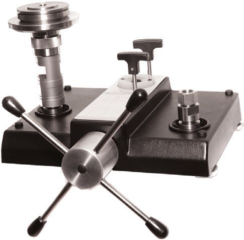
Dead-weight tester in compact design, model CPB3800 Druckwaage in Kompaktausführung, Typ CPB3800 - Dead-weight tester in compact design, model CPB3800
←
→
Transkription von Seiteninhalten
Wenn Ihr Browser die Seite nicht korrekt rendert, bitte, lesen Sie den Inhalt der Seite unten
Operating instructions
                               Betriebsanleitung

Dead-weight tester in compact design, model CPB3800      EN

Druckwaage in Kompaktausführung, Typ CPB3800             DE

   Dead-weight tester in compact design, model CPB3800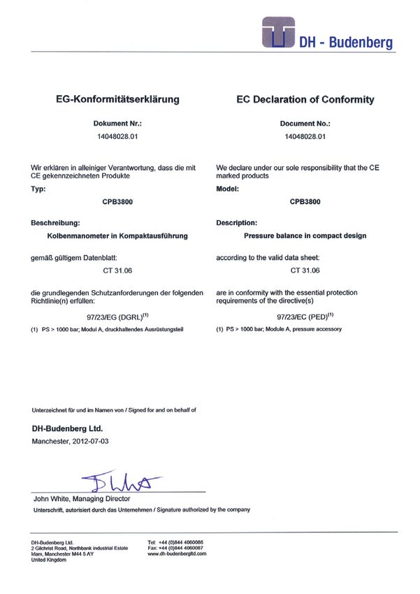
EN Operating instructions model CPB3800                                Page          3 - 46

DE Betriebsanleitung Typ CPB3800                                       Seite       47 - 90

    Further languages can be found at www.wika.com.

   © 2013 WIKA Alexander Wiegand SE & Co. KG
   All rights reserved. / Alle Rechte vorbehalten.
   WIKA® is a registered trademark in various countries.
   WIKA® ist eine geschützte Marke in verschiedenen Ländern.

   Prior to starting any work, read the operating instructions!
   Keep for later use!

   Vor Beginn aller Arbeiten Betriebsanleitung lesen!
   Zum späteren Gebrauch aufbewahren!
                                                                                               14062232.04 03/2015 EN/DE

    2                                              WIKA operating instructions model CPB3800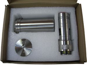
Contents

                            Contents
                            1.   General information                                                 4
                                                                                                         EN
                            2.   Safety                                                              6
                            2.1  Intended use                                                        6
                            2.2  Personnel qualification                                             7
                            2.3  Personal protective equipment                                       7
                            2.4  Special hazards                                                     8
                            2.5  Labelling, safety marks                                            10
                            3.   Specifications                                                     11
                            4.   Design and function                                                20
                            4.1  Description                                                        20
                            4.2  Scope of delivery                                                  20
                            4.3  Base unit                                                          20
                            4.4  Piston unit                                                        23
                            4.5  Function                                                           23
                            5.   Transport, packaging and storage                                   24
                            6.   Commissioning, operation                                           25
                            6.1  Unpacking the dead-weight tester                                   25
                            6.2  Environmental requirement                                          25
                            6.3  Assembly of base units                                             25
                            6.4  Assembly of piston unit                                            26
                            6.5  Assembly of the dead-weight tester                                 27
                            6.6  Procedure                                                          29
                            6.7  Completion                                                         31
                            6.8  Pressure calculation computer software standard accuracy program   32
                            6.9  Temperature measurement of piston units                            32
                            6.10 Cleaning gauges                                                    33
                            7.   Maintenance, cleaning and recalibration                            34
                            7.1  Periodic maintenance                                               34
                            7.2  Corrective maintenance                                             34
                            7.3  Cleaning                                                           38
                            7.4  Recalibration                                                      39
                            8.   Faults                                                             41
14062232.04 03/2015 EN/DE

                            9.   Return and disposal                                                43
                            10.  Accessories                                                        45
                            Appendix: EC Declaration of conformity for model CPB3800                46

                            Declarations of conformity can be found online at www.wika.com.

                            WIKA operating instructions model CPB3800                               3
1. General information
1. General information
■■ The model CPB3800 dead-weight tester in compact design described in the
EN operating instructions has been designed and manufactured using state-of-the-
art technology. All components are subject to stringent quality and environmental
criteria during production. Our management systems are certified to ISO 9001 and
ISO 14001.
■■ These operating instructions contain important information on handling the
instrument. Working safely requires that all safety instructions and work instructions
are observed.
■■ Observe the relevant local accident prevention regulations and general safety
regulations for the instrument’s range of use.
■■ The operating instructions are part of the product and must be kept in the immediate
vicinity of the instrument and readily accessible to skilled personnel at any time. Pass
the operating instructions onto the next operator or owner of the instrument.
■■ Skilled personnel must have carefully read and understood the operating instructions
prior to beginning any work.
■■ The general terms and conditions contained in the sales documentation shall apply.
■■ Subject to technical modifications.
■■ Factory calibrations / DKD/DAkkS calibrations are carried out in accordance with
international standards. 14062232.04 03/2015 EN/DE
4 WIKA operating instructions model CPB38001. General information
■■ Further information:
DH-Budenberg
A division of WIKA Instruments Ltd.
- Internet address: www.wika.de / www.wika.com EN
- Relevant data sheet: CT 31.06
- Application consultant: Tel.: +44 844 4060086
Fax: +44 844 4060087
sales@dh-budenberg.co.uk
WIKA Alexander Wiegand SE & Co. KG
- Internet address: www.wika.de / www.wika.com
- Relevant data sheet: CT 31.06
- Application consultant: Tel.: +49 9372 132-0
Fax: +49 9372 132-406
info@wika.com
Explanation of symbols
WARNING!
... indicates a potentially dangerous situation that can result in serious
injury or death, if not avoided.
CAUTION!
... indicates a potentially dangerous situation that can result in light
injuries or damage to equipment or the environment, if not avoided.
Information
... points out useful tips, recommendations and information for efficient
and trouble-free operation.
14062232.04 03/2015 EN/DE
WIKA operating instructions model CPB3800 52. Safety
2. Safety
WARNING!
EN Before installation, commissioning and operation, ensure that the
appropriate dead-weight tester has been selected in terms of measuring
range, design and specific measuring conditions.
Non-observance can result in serious injury and/or damage to the
equipment.
Further important safety instructions can be found in the individual
chapters of these operating instructions.
2.1 Intended use
Pressure balances (dead-weight testers) are the most accurate instruments available
on the market for the calibration of electronic or mechanical pressure measuring
instruments. By direct measurement of the pressure as the quotient of force and area
(p = F/A), pressure balances (dead-weight testers) are approved as primary standards.
The core component of the CPB3800 is therefore a very precisely-manufactured piston-
cylinder system, onto which a mass load is applied in order to generate the individual
test points. The mass load applied are proportional to the target pressure and this is
achieved through graduated disc weight. A maximum pressure of 1,200 bar must not be
exceeded.
The pressure is set via an integrated, finely-adjustable, precision dual area spindle
pump. As soon as the measuring system reaches equilibrium, there is a balance of
forces between the pressure and the mass load applied.Then the test item can be
calibrated or adjustments can be carried out.
Due to its stand-alone operation (integrated pressure generation and the pure
mechanical measuring principle), the model CPB3800 is ideal for on-site use for
maintenance and service.
The instrument has been designed and built solely for the intended use described here,
14062232.04 03/2015 EN/DE
and may only be used accordingly.
The technical specifications contained in these operating instructions must be
observed. Improper handling or operation of the instrument outside of its technical
specifications requires the instrument to be taken out of service immediately and
inspected by an authorised DH-Budenberg/WIKA service engineer.
6 WIKA operating instructions model CPB38002. Safety
Handle mechanical precision measuring instruments with the required care (protect
from humidity, impacts, strong magnetic fields, static electricity and extreme
temperatures, do not insert any objects into the instrument or its openings). EN
If the instrument is transported from a cold into a warm environment, the formation of
condensation may result in instrument malfunction. Before putting it back into operation,
wait for the instrument temperature and the room temperature to equalise.
The manufacturer shall not be liable for claims of any type based on operation contrary
to the intended use.
2.2 Personnel qualification
WARNING!
Risk of injury should qualification be insufficient!
Improper handling can result in considerable injury and damage to
equipment.
■■ The activities described in these operating instructions may only be
carried out by skilled personnel who have the qualifications described
below.
■■ Keep unqualified personnel away from hazardous areas.
Skilled personnel
Skilled personnel are understood to be personnel who, based on their technical training,
knowledge of measurement and control technology and on their experience and
knowledge of country-specific regulations, current standards and directives, are capable
of carrying out the work described and independently recognising potential hazards.
Special operating conditions require further appropriate knowledge, e.g. of aggressive
media.
DH-Budenebrg/WIKA can provide dedicated training courses on the correct use of our
products. Please contact your local office for further details.
14062232.04 03/2015 EN/DE
2.3 Personal protective equipment (P.P.E.)
The personal protective equipment is designed to protect the skilled personnel from
hazards that could impair their safety or health during work. When carrying out the
various tasks on and with the instrument, the skilled personnel must wear personal
protective equipment.
WIKA operating instructions model CPB3800 72. Safety
Follow the instructions, displayed in the work area, regarding personal
protective equipment!
EN
The required personal protective equipment must be provided by the operating
company.
Wear safety goggles!
Protect eyes from flying particles and liquid splashes.
Wear protective gloves!
Protect hands from contact with aggressive media.
2.4 Special hazards
WARNING!
To ensure safe working on the instrument, the operating company must
ensure
■■ that suitable first-aid equipment is available and aid is provided
whenever required.
■■ that the operating personnel are regularly instructed in all topics
regarding work safety, first aid and environmental protection and
knows the operating instructions and, in particular, the safety
instructions contained therein.
WARNING!
Residual media at the dead-weight tester can result in a risk to persons,
the environment and the equipment. Take sufficient precautionary
measures.
2.4.1 Mineral oils health and safety information
14062232.04 03/2015 EN/DE
DH-Budenberg/WIKA provide hydraulic mineral oil in 500 ml containers labelled “ISO
VG 22” for use up to 4,000 bar in dead-weight testers. It is no more hazardous than other
common lubricating oils.
8 WIKA operating instructions model CPB38002. Safety
It is the nature of the way in which this equipment is used, that there
could be frequent and/or prolonged skin contact; in a few individuals this
could give rise to skin irritation (Keratosis or Dermatitis). The use of an
effective barrier cream and/or protective gloves will greatly reduce this EN
possibility.
Description
Closed flash point greater than 120 °C
Storage not above 30 °C
Oral LD 50 15 g per kg body weight
Threshold limit value 5 mg/m³
Fire extinguishing media CO2/dry chemical foam or water fog
Spillage Soak with absorbent clay or proprietary absorbent
Waste disposal Burn or dump in approved area
Emergency treatment of acute effects
Ingestion Do not induce vomiting.
Administer 250 ml milk or olive oil.
The main hazard following accidental ingestion is aspiration
of liquid into lungs.
Aspiration Send to hospital immediately
Inhalation Remove to fresh air, if nausea persists seek medical
attention.
Eye contact Wash with copious amounts of water for at least 10 minutes.
If irritation results or persists, obtain medical advice.
Skin contact Where skin rashes or other abnormalities occur as a result
of prolonged or repeated contact, medical advice should be
obtained as soon as possible.
2.4.2 Other liquids
For some very particular applications we supply specially constructed liquids. Copies of
manufacturer’s data can be sent on request.
14062232.04 03/2015 EN/DE
WIKA operating instructions model CPB3800 92. Safety
2.4.3 Lifting of masses
WARNING!
EN Care must be taken when lifting the masses onto the dead-weight tester.
Each mass must be lifted individually and never attempt to lift stack of
masses on or off the dead-weight tester.
2.5 Labelling, safety marks
Product label
For an explanation of
symbols, see below.
Serial No.
Pressure range
Date of manufacture
Explanation of symbols
Before mounting and commissioning the instrument, ensure you read the
operating instructions!
CE, Communauté Européenne
Instruments bearing this mark comply with the relevant European
directives.
14062232.04 03/2015 EN/DE
10 WIKA operating instructions model CPB38003. Specifications
3. Specifications
Piston-cylinder systems (standard)
EN
Measuring range 1) bar 1 … 120 2.5 ... 300 5 ... 700 10 ... 1,200
Required masses kg 41 50 58 50
Smallest step 2) bar 1 2.5 5 10
(Standard mass set)
Nominal effective area of the in² 1/16 1/40 1/80 1/160
piston
Measuring range 1) lb/in² 10 … 1,600 25 ... 4,000 50 ... 10,000 100 ... 16,000
Required masses kg 47 47 58 47
Smallest step 2) lb/in² 10 25 50 100
(Standard mass set)
Nominal effective area of the in² 1/16 1/40 1/80 1/160
piston
Accuracies
Standard 3) 4) 0.05 % of reading
Option 3) 4) 0.025 % of reading
Pressure transmission medium Hydraulic fluid based on VG22 mineral oil (0.5 l included in scope
of delivery)
Material
Piston Tungsten carbide
Cylinder Tungsten carbide
Mass set Stainless steel, non-magnetic
Weight
Piston-cylinder system kg 2.4
BAR mass set incl. mass carrier kg 41.5 50.5 58.5 50.5
lb/in² mass set incl. mass carrier kg 47.5 47.5 58.5 47.5
Storage case for mass set kg 5.8
(optional, 2 pieces required)
Dimensions
Storage case for mass set 400 x 310 x 310 mm (W x H x D) and
(optional) 215 x 310 x 310 mm (W x H x D)
14062232.04 03/2015 EN/DE
1) Theoretical starting value; corresponds to the pressure value generated by the piston or the piston and its make-up weights (by
their own weight). To optimise the operating characteristics more masses should be loaded.
2) The smallest pressure change value that can be achieved based on the standard mass set. To reduce this, a set of fine
increment masses is also available.
3) The accuracy from 10 % of the measuring range is based on the measured value. In the lower range, a fixed error based on
10 % of the range applies.
4) Measurement uncertainty assuming reference conditions (ambient temperature 20 °C, atmospheric pressure 1,013 mbar,
relative humidity 40 %). For operation without a CalibratorUnit, corrections must be made if required.
WIKA operating instructions model CPB3800 113. Specifications
Base
Connections
EN Connection for piston-cylinder G ¾ B (male)
system
Test item connection G ½ female thread, loose union connection
Material
Wetted parts Austenitic stainless steel, high tensile brass, nitrile rubber
Pressure transmission Hydraulic fluid based on VG22 mineral oil (0.5 l included in scope of
medium delivery) 5)
Reservoir 170 cm³
Weight
Base 13.5 kg
Storage case for the base 8.5 kg
(optional)
Permissible ambient conditions
Operating temperature 18 ... 28 °C
Dimensions
Base 401 x 397 x 155 mm ) (W x D x H), for details, see technical drawings
5) Other pressure transmission media on request.
CE conformity and certificates
CE conformity
Pressure equipment directive 97/23/EC (Module A)
Certificate
Calibration Calibration certificate
Option: UKAS calibration certificate (pressure calibration with a mass
set) for CPB3800 standard models
Option: UKAS calibration certificate (area and mass calibration) for
CPS/CPM5800 only
14062232.04 03/2015 EN/DE
Approvals and certificates, see website
For further specifications see WIKA data sheet CT 31.06 and the order documentation.
12 WIKA operating instructions model CPB38003. Specifications
Tables of masses
The following tables show, for the respective measuring range, the number of masses
within a mass set, with their resulting nominal pressures.
EN
Should the instrument not be operated under reference conditions (ambient temperature
20 °C, atmospheric pressure 1,013 mbar, relative humidity 40 %), relevant corrections
must be made.
The disc weights are manufactured, as standard, to standard gravity of 9.80665 m/s².
As an optional extra, mass sets can be manufactured for customer local gravity value.
Standard mass sets
Measuring range 1 ... 120 2,5 ... 300
[bar] Quantity Nominal Quantity Nominal
pressure per pressure per
piece piece
[bar] [bar]
Piston and make-up weight 1 1 1 2.5
Piston, mass carrier and mass carrier 1 20 1 50
make-up weight
Masses (stackable on mass carrier ) 3 20 3 50
Masses (stackable on piston) 1 20 1 50
1 10 1 25
2 4 2 10
1 2 1 5
1 1 1 2.5
Measuring range 5 ... 700 10 ... 1.200
[bar] Quantity Nominal Quantity Nominal
pressure per pressure per
piece piece
[bar] [bar]
Piston and make-up weight 1 5 1 10
Piston, mass carrier and mass carrier 1 100 1 200
make-up weight
14062232.04 03/2015 EN/DE
Masses (stackable on mass carrier) 4 100 3 200
Masses (stackable on piston) 1 100 1 200
1 50 1 100
2 20 2 40
1 10 1 20
1 5 1 10
WIKA operating instructions model CPB3800 133. Specifications
Measuring range 10 ... 1,600 25 ... 4,000
[lb/in²] Quantity Nominal Quantity Nominal
pressure per pressure per
EN piece piece
[lb/in²] [lb/in²]
Piston 1 10 1 25
Mass carrier and mass carrier make- 1 190 1 475
up weight
Masses (stackable on mass carrier) 5 200 5 500
Masses (stackable on piston) 1 200 1 500
1 100 1 250
2 40 2 100
1 20 1 50
1 10 1 25
Measuring range 50 ... 10,000 100 ... 16,000
[lb/in²] Quantity Nominal Quantity Nominal
pressure per pressure per
piece piece
[lb/in²] [lb/in²]
Piston 1 50 1 100
mass carrier and mass carrier make- 1 950 1 1,900
up weight
Masses (stackable on mass carrier) 7 1,000 5 2,000
Masses (stackable on piston) 1 1,000 1 2,000
1 500 1 1,000
2 200 2 400
1 100 1 200
1 50 1 100
14062232.04 03/2015 EN/DE
14 WIKA operating instructions model CPB38003. Specifications
Transport dimensions for complete instrument
The complete instrument, in its standard version and standard scope of delivery,
consists of three packages on a single pallet.
The dimensions are 1,200 x 800 x 500 mm. EN
The overall weight is dependant on the measuring range.
Standard CPB3800 units
Weight in kg Weight in kg
Version in bar net gross Version in lb/in² net gross
1 … 120 bar 71 89 10 ... 1,600 lb/in² 68 86
2.5 … 300 bar 71 89 25 ... 4,000 lb/in² 68 86
5 … 700 bar 71 89 50 ... 10,000 lb/in² 68 86
10 … 1,200 bar 71 89 100 ... 16,000 lb/in² 68 86
Optional CPS/CPM5800 units with CPB3800 base
Weight in kg Weight in kg
Version in bar net gross Version in psi net gross
Single-piston measuring ranges Single-piston measuring ranges
1 … 120 bar 77 95.5 10 … 1,600 psi 73 91.5
2 … 300 bar 77 95.5 30 … 4,000 psi 72.5 91
Dual-piston measuring ranges Dual-piston measuring ranges
1 … 60 bar / 85.5 104 10 … 800 psi / 84.5 103
10 … 700 bar 100 … 10,000 psi
1 … 60 bar / 77.5 96 10 … 800 psi / 73 91.5
20 … 1,200 bar 200 … 16,000 psi
1 … 60 bar / 85.5 104 10 … 800 psi / 84.5 103
20 … 1,400 bar 200 … 20,000 psi
14062232.04 03/2015 EN/DE
WIKA operating instructions model CPB3800 153. Specifications
Dimensions in mm
(without disc weigths)
EN Front view
Side view
14062232.04 03/2015 EN/DE
16 WIKA operating instructions model CPB38003. Specifications
Top view
2
6 EN
7
3
5
8
1
4
(1) Test item connection
(2) High-pressure shut-off valve
(3) Low-pressure shut-off valve
(4) Dual-area spindle pump with star handle
(5) Piston-cylinder system
(6) Rotatable feet
(7) Reservoir with screwed sealing plug
(8) Pressure generation control schematic
14062232.04 03/2015 EN/DE
WIKA operating instructions model CPB3800 173. Specifications
Standard connection piston-cylinder system
EN O-ring 8.9 x 1.9
Oil collecting tray
Test connection
Adapter, see scope
of delivery
Sealing ring
USIT 10.7 x 18 x 1.5
Oil collecting tray
14062232.04 03/2015 EN/DE
When using thread adapters, the thread adapter has to be connected
pressure tight to the test item first.
After that the test item with mounted adapter can be inserted into the test
connection and can be oriented.
18 WIKA operating instructions model CPB38003. Specifications
Liquids used
A hydraulic mineral oil viscosity 20 ... 37 cSt at 40 °C viscosity grade VG20 to VG37
to ISO 3448 (BS 4231) is used for the CPB3800 base unit. Most users will be able to
obtain locally suitable oil (see below) as used in hydraulic machinery. However, for the EN
convenience of users we can supply a 500 ml bottle of oil, viscosity grade VG22.
Oils suitable for dead-weight testers
The following oils are the commercially available oils suitable for use in the dead-weight
testers.
ISO 3448 Approx. SAE Shell Esso Mobil
viscosity viscosity clas-
grade sification
VG22 -- Tellus 22 Nuto H22 DTE 22
Tellus R22
VG32 10W Tellus V32 Nuto H32 DTE Oil Light
DTE 24
VG37 -- Tellus 37 -- --
Tellus R37
Tellus T37
Tellus V37
Other liquids
The dead-weight tester model CPB3800 is manufactured for use on mineral oil only. If
an end user wishes to use it on another fluid, it is the end user responsibility to ensure
that the fluid is compatible with high tensile brass, stainless steel, mild steel, and nitrile
rubber, which are the materials that will come into contact with the fluid.
Fluids, which attack ABS, should be used with caution. Continual
immersion of the cover in such fluids will cause deterioration. Spillages
should be wiped off immediately.
Wear safety goggles!
14062232.04 03/2015 EN/DE
Protect eyes from flying particles and liquid splashes.
Wear protective gloves!
Protect hands from contact with aggressive media.
WIKA operating instructions model CPB3800 194. Design and function
4. Design and function
4.1 Description
EN The model CPB3800 dead-weight tester in compact design provides optimum features
for laboratory use whilst being rugged enough for industrial requirements. It provides a
highly accurate measurement of pressure.
The piston unit is screwed on to the left hand side pressure block of the base unit and
the test item is connected to the right hand pressure block.
4.2 Scope of delivery
■■ Base
■■ Dual-area spindle pump for filling, pressure generation and fine pressure adjustment
■■ Piston connection with G ¾ B male thread
■■ Test item connection with G ½ female thread, loose union connection
■■ Adapter set for test item connection selectable from 3 different sets:
- Adapter set “BSP” G ½ male on G ⅛, G ¼, G ⅜ and G ½ female
- Adapter set “NPT” G ½ male on ⅛ NPT, ¼ NPT, ⅜ NPT and ½ NPT female
- Adapter set “metric” G ½ male on M12 x 1.5 and M20 x 1.5 female
■■ Piston-cylinder system
■■ Mass set manufactured to standard gravity (9.80665 m/s²)
■■ VG22 mineral oil (0.5 litre)
■■ Tool and maintenance set consisting of:
1 hexagon wrench key 3 mm A/F
2 x 30 mm A/F open-ended spanners
1 spirit level
4 level plates
1 bag of seals
1 G ½ (½” BSP) angle connection
1 pointer press-on tool
1 pointer remover
1 test item connection
■■ Operating instructions in German and English language
■■ Factory calibration certificate
14062232.04 03/2015 EN/DE
Cross-check scope of delivery with delivery note.
4.3 Base unit
The model CPB3800 series base unit consists of a solid aluminium base plate mounted
on four adjustable levelling feet, a spindle pump, reservoir, control valves, pipework to
20 WIKA operating instructions model CPB38004. Design and function
two stainless steel pressure connection blocks. The pipework and above mentioned
assemblies are covered by an easy to clean ABS cover.
4.3.1 Spindle pump EN
The spindle pump is bolted to the reservoir/high pressure cylinder block fastened to the
base unit. A sectioned view of the pump is shown. The rotating handwheel (C) which
is operated by the spokes (D) is attached to a threaded spindle (E). The spindle is
supported in a sintered bearing (F). As the spindle (E) is rotated, it drives a non-rotating
ram (E and K) forward, the thrust being taken by a needle thrust bearing (G). The large
diameter of the ram (H) in the barrel of the pump (J) primes the pressure system and
provides the low pressure up to approximately 140 bar (2,000 lb/in²). The small diameter
of the ram (K) in the reservoir/ high pressure cylinder block provides the higher test
pressures up to 1,200 bar (16,000 lb/in2).
4.3.2 Reservoir
A liquid reservoir is provided on the top of reservoir/high pressure cylinder block.
The reservoir is provided with a translucent cover to enable the reservoir level to be
monitored. A plug in the middle of the reservoir cover to allow the reservoir to be filled
or topped up (the plug is removed whilst the dead-weight tester is in use). The reservoir
contains enough liquid (approximately 150 cm³) to enable normal operation of the
dead-weight tester to be carried out.
Low pressure ram displacement = 60 cm³
High pressure ram displacement = 10 cm³
4.3.3 Control valves
Two control valves are provided on the top of reservoir/high pressure cylinder block.
The valve mechanisms are built into the reservoir/high pressure cylinder block and they
control the flow of liquid through internal drillings in the reservoir/high pressure cylinder
block. The rear valve is referred to as valve A and is used to control the output from the
larger diameter ram of the spindle pump. The front valve is referred to as valve B and is
used to control the flow of liquid to and from the reservoir.
4.3.4 Connection blocks
Pressure supply pipes from the spindle pump are terminated at two pressure blocks
mounted on the base unit. The pressure blocks are fitted with threaded bosses
14062232.04 03/2015 EN/DE
projecting up through the cover plate of the base unit. These threaded bosses enable
piston units to be directly screwed on to them or connections for various sizes of gauge
connections to be screwed on to them. Oil cups are fitted to the unit cover around the
threaded bosses of the connection blocks to catch any oil drips from the gauge stand
during gauge fitting and removal.
WIKA operating instructions model CPB3800 214. Design and function
Sectioned view of spindle pump
EN
K
H
J
E
G
14062232.04 03/2015 EN/DE
D
F
C
22 WIKA operating instructions model CPB38004. Design and function
4.4 Piston unit
The piston unit of the model CPB3800 is a single range piston unit, which covers the
range up to 1,200 bar (16,000 lb/in²).
Masses are loaded directly onto the piston head for low pressure calibration points. A EN
coloured band indicates when the piston is floating.
For higher pressure points, a mass carrier is fitted directly to the piston head, and disc
weights located at the bottom of the mass carrier or located on top of it. A machined
groove on the main piston body indicates when the piston is floating.
4.5 Function
Operation of the dead-weight tester is controlled by the two valves A and B on the top
of the reservoir/high pressure cylinder block. When initially priming the system valves A
and B are opened to fill the system with oil from the reservoir. Valve B is then closed with
valve A left open and the spindle pump operated to provide the lower test pressures.
To provide the higher pressures valve A is closed to seal off the test circuit from the low
pressure part of the spindle pump and valve B is opened to allow the liquid in the low
pressure part of the spindle pump to return to the reservoir as the pump is operated.
This ensures that the pump can be operated without having to put large forces on the
spindle pump handwheel. To release the test pressure the spindle pump is wound out
and valve A is opened.
Valve A
Reservoir
14062232.04 03/2015 EN/DE
Valve B
Hand pump
WIKA operating instructions model CPB3800 235. Transport, packaging and storage
5. Transport, packaging and storage
5.1 Transport
EN Check the model CPB3800 dead-weight tester for any damage that may have been
caused by transport. Obvious damage must be reported immediately.
5.2 Packaging
Do not remove packaging until just before mounting.
Keep the packaging as it will provide optimum protection during transport (e.g. change
in installation site, sending for repair or recalibration).
Disc weights are shipped in cardboard and not in their respective
wooden cases, if ordered.
Wooden cases are not suitable for use as shipping cases.
5.3 Storage
Permissible conditions at the place of storage:
■■ Storage temperature: -10 ... +50 °C
■■ Humidity: 35 ... 85 % relative humidity for instrument base and mass set
35 ... 65 % relative humidity for piston-cylinder system (no condensation)
Avoid exposure to the following factors:
■■ Direct sunlight or proximity to hot objects
■■ Mechanical vibration, mechanical shock (putting it down hard)
■■ Soot, vapour, dust and corrosive gases
■■ Potentially explosive environments, flammable atmospheres
■■ Corrosive liquids
Store the model CPB3800 dead-weight tester in its original packaging in a location that
fulfils the conditions listed above. If the original packaging is not available, pack and
store the instrument as described below:
1. Wrap the instrument in an antistatic plastic film.
2. Place the instrument, along with shock-absorbent material, in the packaging.
14062232.04 03/2015 EN/DE
3. If stored for a prolonged period of time (more than 30 days), place a bag, containing a
desiccant, inside the packaging.
24 WIKA operating instructions model CPB38006. Commissioning, operation
6. Commissioning, operation
6.1 Unpacking the dead-weight tester
As soon as possible after delivery open the packaging of the deat-weight tester and EN
check that you have all the items detailed in the packing list (see chapter 4.2 “Scope
of delivery”). As you are unpacking the items, examine them for signs of damage or
breakage during transit.
If any items are missing get in touch immediately with DH-Budenberg/WIKA to inform us
of the shortage.
6.2 Environmental requirement
When siting the dead-weight tester if not in a temperature controlled laboratory look for
an area that satisfies the following criteria as much as possible:
■■ A constant temperature area free from draughts and sources of heat or cold
■■ An area free from noise and vibration, constantly used pathways
■■ A clean dry area free from corrosive liquids or vapours
A strong, stable, level table or workbench with the capability of supporting the system
with sufficient space to operate is required.
6.3 Assembly of base units
Fastening base to bench
The base is to be mounted on a firm, level table or bench about 0.9 m high. The centre
line of the front adjustable feet of the unit should be about 40 mm from the front edge of
the bench to allow adequate clearance for the handwheel.
1. Mark the position of the adjustable feet of the unit on the top of the bench.
2. Position a level plate at the centre of each of the adjustable feet of the unit and screw
the plate to the bench to ensure that the dead-weight tester is rigid.
3. Fit the base unit on the bench with the adjustable feet on the level plates and the
handwheel shaft projecting over the front of the bench.
4. Screw in the four handwheel spokes into the hub.
5. Using the spirit level provided, level the unit in both the front/rear axis and the side
14062232.04 03/2015 EN/DE
to side axis by adjusting the four knurled feet, by placing the spirit level on top of the
piston-cylinder system.
WIKA operating instructions model CPB3800 256. Commissioning, operation
6.4 Assembly of piston unit
The piston unit of the CPB3800 has its own transportation box that should be used for
storing the unit when not in operation, and if the customer ever has to send the unit
EN back for recalibration. The following details show how the piston is to be assembled/
disassembled to the main body.
1. Unscrew the knurled retaining cap from the main body.
2. Place the piston head on a flat surface, with the piston facing vertically.
3. Fit the knurled retaining cap to the piston via the eccentric hole.
4. Place the main piston body with the external thread in a vertical position.
5. Lubricate the piston with the pressure medium, and insert the piston into the cylinder
in the main body in a vertical direction only.
WARNING!
Do not apply any transverse force. Excess force is not required.
6. Tighten the knurled retaining cap to the main body.
7. Lift the piston head until it engages against its internal stop. This movement should
be free.
Mass carrier
Main body
Piston head
14062232.04 03/2015 EN/DE
26 WIKA operating instructions model CPB38006. Commissioning, operation
6.5 Assembly of the dead-weight tester
1. Fit the piston unit to the left hand connection. Ensure that the mating faces are clean
and the 12 mm diameter O-ring seal correctly located. Excess force is not required
to achieve an effective seal. EN
2. Check the level of the system base with the spirit level on the piston-cylinder
system. Level if necessary by using the levelling screws. If using as a comparator, fit
additional loose union connection (order number 14031251) to port that piston unit
would be fitted to.
3. Fit the appropriate connection to the gauge stand, using a bonded seal to make the
joint and screw a test gauge (for installation use a known gauge) into position, also
with a bonded seal.
If preferred, a copper or leather washer can be substituted for the bonded seal at
the gauge. The loose nut on the dead-weight tester base enables the gauge to be
positioned as required and for back connection gauges the angle connection is
screwed into the loose union connection.
When using thread adapters, the thread adapter has to be connected
pressure tight to the test item first.
After that the test item with mounted adapter can be inserted into the test
connection and can be oriented.
6.5.1 Filling the base unit with liquid
1. Remove filler plug from reservoir by prising plug out. (This plug should be left out
whilst in use).
2. Open valves A and B.
3. Wind spindle pump handle fully clockwise.
4. Fill reservoir with appropriate liquid. Use the oil supplied or an approved substitute
for oil systems. Do not use other liquids. Castor based oils, Skydrol, solvents or
similar liquids will attack the seals fitted in the dead-weight tester.
5. Wind spindle pump handle fully anti-clockwise.
6. Top up reservoir if necessary.
14062232.04 03/2015 EN/DE
Wear safety goggles!
Protect eyes from flying particles and liquid splashes.
WIKA operating instructions model CPB3800 276. Commissioning, operation
Wear protective gloves!
Protect hands from contact with aggressive media.
EN
6.5.2 Post assembly test
1. Carry out a test calibration of a known instrument (see chapter 6.6 “Procedure”) to
ensure that the unit is working correctly.
2. Release the pressure and remove the test instrument.
To remove the instrument from the system, use the appropriate size
of spanners on the top section of the pressure connection and on the
body of the instrument only. Ensure that the lower part of the pressure
connection is not rotated as this may release it from the base.
3. The system is now ready for use.
CAUTION!
If the volume required to be filled is very large requiring the use of an
additional pump and reservoir to be connected to the model CPB3800,
it is ESSENTIAL to ensure that valve B is kept open and valve A closed
at all times otherwise a high pressure can be built up on the low pressure
ram of the screw press and damage caused. To ensure this does not
happen we can supply the system fitted with a relief valve, which will
release at a set pressure, should the valve operation be incorrect.
Alternatively, we can supply a modified system and hand pump for this
operation. For further information on both items contact DH-Budenberg/
WIKA.
When testing equipment with a large volume, the capacity of the spindle
pump (65 cm³) may be insufficient to reach the pressure required. In this
case, the equipment should be filled as far as possible with the liquid
before connecting it to the system, so that the displacement needed is
14062232.04 03/2015 EN/DE
reduced.
Dirty or chemically contaminated test items should not be fitted as they
contaminate the system unless they are first cleaned.
28 WIKA operating instructions model CPB38006. Commissioning, operation
Wear safety goggles!
Protect eyes from flying particles and liquid splashes.
EN
Wear protective gloves!
Protect hands from contact with aggressive media.
6.6 Procedure
1. Fit instrument to be tested to gauge stand.
2. Load the masses equivalent to the desired pressure. Each mass is marked with its
pressure value. The piston-cylinder system has a basic lb/in² start, for other pressure
units a make-up weight is added to the piston head for conversion to bar.
For calibrating pressures less than the pressure value of the mass carrier
make-up weight value, it is recommended that the top loading disc
weights are used for calibration. When the required pressure calibration
unit is bar, it is essential that the small make-up weight is fitted first
before any other top loading disc weights.
For calibrating pressures greater than the pressure value mass carrier
make-up weight value, the mass carrier should be fitted. All disc weights
must be removed before fitting the mass carrier.
When the mass carrier is fitted, the initial masses that goes onto it is a
large annular make-up weight. The small type make-up weight should not
be used when the mass carrier is fitted.
6.6.1 To apply pressure
For pressures up to 140 bar (2,000lb/in²)
1. Close valve B (valve A remaining open).
2. Wind spindle pump handle clockwise. This will generate pressure up to approxi-
14062232.04 03/2015 EN/DE
mately 140 bar or 2,000 lb/in², as handle is wound in. When handle becomes stiff to
rotate this will indicate that the pressure limit for this range has been reached.
WIKA operating instructions model CPB3800 296. Commissioning, operation
For pressures above 140 bar (2,000lb/in²)
1. Ensure valve B closed and valve A open.
2. Wind spindle pump handle clockwise until the handle becomes stiff to operate.
EN
3. Close Valve A and open valve B.
4. Continue to wind spindle pump handle clockwise. This will generate pressure up to
approximately 1,200 bar or 16,000 lb/in².
5. When the piston rises and appears to floats, this indicates it is at its nominal desired
pressure. When only disc weights are being utilised, a blue and yellow band
indicates the float position. When the mass carrier is being employed, the bottom of
the mass carrier will line up with a machined groove in the piston holders main body,
to indicate its nominal desired pressure.
6.6.2 During calibration
When the dead-weight tester is correctly set up and there are no leaks the piston
should “float” for many minutes without it being necessary to touch the spindle pump
handwheel. On the initial setting up, however, there may be some air trapped in the base
of the piston/cylinder unit. As this leaks past the piston the masses may fall slightly but it
will only be for a matter of a few minutes until the air has escaped. If the piston continues
to fall, check the connections for leaks.
During calibration, the masses should be rotated by hand. It is desirable that the masses
should only be rotated when approximately the correct pressure is obtained. Masses
should not be brought to rest by fully releasing the pressure and allowing the piston
head to rotate against its stop under the full load of the mass pile.
It is essential that the masses spin freely during readings. The piston stops moving when
the pressure is too high or too low. At the lowest pressures the masses will not spin for
more than a few seconds unless a very thin oil is used, but providing the mass is rotated
by hand before taking a reading and is obviously “floating” an accurate reading will be
given.
CAUTION!
Care should be exercised at all times when rotating the masses. Failure
14062232.04 03/2015 EN/DE
to do so may cause damage to the actual piston unit, or possibly injury to
the operator.
Therefore, the rotational motion should be stopped by hand. Only then
new masses for further test points can be placed or the pressure can be
released completely.
30 WIKA operating instructions model CPB38006. Commissioning, operation
6.6.3 Datum levels
When testing gauges on liquid it is occasionally necessary to take into account heads
of liquid since a height difference of 10 mm corresponds to approximately 1 mbar. The
datum levels of the models CPB3800 piston units are marked with a groove on the EN
outer diameter of the piston unit. It should be noted that when the dead-weight tester is
re-calibrated by a laboratory other than DH-Budenberg/WIKA, the datum level at which
the tests have been carried out may differ from this standard and therefore allowance
should be made for any variation.
The drawing shows the head effect that may have to be compensated for when high
accuracy calibration is desired. The following formula will enable the head correction to
be calculated.
▲P due to head effects
Pressure (Pa) = σ•H•g
Where
σ = density (kg/m³)
H = height (in metres)
g = gravity (m/s²)
Density of VG 22 oil = 885 kg/cm³
Cylinder datum
Zero buoyancy datum
14062232.04 03/2015 EN/DE
WIKA operating instructions model CPB3800 316. Commissioning, operation
6.7 Completion
1. After the test is finished wind spindle pump handle anti-clockwise to lower pressure.
EN 2. Gently open valve A or B to release residual pressure.
3. Ensure that both valves A and B are fully open.
The system is now ready for another test and any residual pressure is relieved.
6.8 Pressure calculation computer software standard accuracy program
This software enables the user to define his equipment and local conditions (gravity,
temperature), so that when nominal pressures are entered, actual achieved pressures
are displayed
These actual pressures will then be to the standard accuracy of the dead-weight tester.
To achieve the improved standard accuracy the user must enter the correction factor
given on the improved accuracy certificate supplied with the piston unit.
Default conditions are input at DH-Budenberg/WIKA but once the user alters these, his
values then become the default (no need to repeatedly insert your values).
This program has been written to aid users to maintain the standard
accuracy of DH-Budenberg/WIKA dead-weight tester. It has not been
written for use with any other makes of dead-weight testers.
The software can be accessed from the supplied CD in the folder “Customer Software”
and “Standard Accuracy DWT”. Installation/Operating instructions should be read before
using the software.
6.9 Temperature measurement of piston units
For many purposes, such as calibrating most type of dial gauges and sensors, accurate
knowledge of the temperature of a piston unit is not necessary. However, in order to
achieve the utmost accuracy from a dead-weight tester it is important to know the
temperature of the piston unit as close as possible to the working part of the unit.
14062232.04 03/2015 EN/DE
In laboratories where the room temperature is controlled it is most likely that the
temperature of the working parts of the unit will not differ from the ambient temperature
by more than 0.5 °C. When working in uncontrolled temperatures, however, one would
have to measure the temperature of the piston unit.
32 WIKA operating instructions model CPB38006. Commissioning, operation
A possible way to do this is to use a disc shaped thermistor type probe sensing element
taped to the outer surface of the piston unit. The sensing element should be insulated
from the ambient temperature by covering the element with a thin strip of polystyrene,
or other insulating material, then taping this to the piston unit. Alternatively, a model EN
CPU6000 CalibratorUnit may be used.
We can supply a suitable instrument. Please contact DH-Budenberg/WIKA.
6.10 Cleaning gauges
This cleaning/degreasing process is only suitable for use with pressure gauges with
either phosphor bronze, beryllium copper, monel or stainless steel bourdon tubes in the
form of a “C”.
It is not advisable to degrease pressure gauges with steel bourdon tubes since a very
small amount of corrosion on the bore of a bourdon tube can cause inaccuracies of
reading and early failure of the tube.
Wear safety goggles!
Protect eyes from flying particles and liquid splashes.
Wear protective gloves!
Protect hands from contact with aggressive media.
This method of cleaning is not suitable for use with pressure gauges which are fitted
with coiled bourdon tubes, nor any gauges which are to be used on oxygen, as
complete removal of oil is not assured. Please contact DH-Budenberg/WIKA.
Equipment
This consists of a syringe and a special needle with the point bent through 90°.
14062232.04 03/2015 EN/DE
Instructions
1. Fill syringe with solvent (suitable cold degreasing liquid).
2. With gauge connection pointing upwards put needle into connection and insert by
feel the point into the hole leading to the tube.
WIKA operating instructions model CPB3800 336. Commissioning, operation / 7. Maintenance, cleaning ...
3. Inject the solvent. Ideally the tube should be half full.
4. Shake gauge in various attitudes to agitate solvent.
EN 5. Suck solvent back into syringe, holding gauge at an angle.
6. Check that solvent removed is clean. To be sure that all oil has been removed,
repeat cleaning process until solvent removed from gauge is as clean as that put in.
Removing the
Filling with solvent
solvent
Cleaning of gauges
7. Maintenance, cleaning and recalibration
7.1 Periodic maintenance
Repairs must only be carried out by the manufacturer.
Cleaning the units and checking the liquid levels is the only periodic maintenance
required. With normal use, no further maintenance should be necessary. If required, the
system can be returned to the manufacturer for re-conditioning. Accuracy, overhaul and
re-certification are also explained in chapter 7.4.1 “Factory overhaul and re-certification
14062232.04 03/2015 EN/DE
of dead-weight testers maintenance of accuracy”.
Fluids, which attack ABS, should be used with caution. Continual
immersion of the cover in such fluids will cause deterioration. Spillage’s
should be wiped off immediately.
34 WIKA operating instructions model CPB38007. Maintenance, cleaning and recalibration
7.2 Corrective maintenance
7.2.1 General
This section contains details on stripping the unit and replacing the spare parts which
EN
are listed (see chapter 10 “Accessories”). The component identification numbers in
brackets in each procedure refer to the following figure.
7.2.2 Removing the cover
1. Drain as much oil as possible from the dead-weight tester by winding the screw-
press fully clockwise and using a drain screwed in the gauge stand.
2. Unscrew the loose union connection and piston-cylinder system.
3. Remove the oil cups by levering upwards carefully.
4. Slacken the socket set screw using a 3 mm hexagon wrench key and remove both
handwheels.
5. Remove the four cover retaining screws and lift off the cover.
7.2.3 Reservoir seals
1. Unscrew two screws and remove the reservoir cover
2. Remove the O-ring seal (6) from the recess and the seloc seal (7) from the screws.
3. On replacement ensure all sealing faces are absolutely clean and do not overtighten
screws.
7.2.4 Valve seals
1. Unscrew the gland nut.
2. Unscrew the valve spindle and remove the bonded seal.
3. Slide gland nut off spindle.
4. Using a suitable hooked tool remove the O-ring seal (9) from the bore of the gland
nut. Renew O-ring and bonded seal (10).
5. On replacement ensure that O-ring is correctly located in the groove and all sealing
faces are clean. Remove all burrs from spindle.
14062232.04 03/2015 EN/DE
7.2.5 Spindle pump
1. Using a 4 mm hexagon wrench key unscrew the six socket head cap screws secur-
ing the hub locating plate. (These are positioned inside the recess in the back of the
aluminium hub).
WIKA operating instructions model CPB3800 357. Maintenance, cleaning and recalibration
2. By carefully pulling the hub the complete ram assembly can now be withdrawn from
the barrel (During this operation a container is required beneath the barrel to catch
any liquid).
EN 3. Unscrew the ram from the hub assembly.
4. The high pressure seal (12) and low pressure seal (15) can now be replaced. Before
fitting the new seals check the ram is not scored on the locating diameters.
5. At this point the hub assembly should be checked for excess play indicating wear in
the bearing and for wear in the screwed spindle and nut. If any wear is found it will be
necessary to dismantle the hub assembly.
6. Check the bore of the block assembly (11) is not badly scored or pitted. If a replace-
ment is required this item is supplied complete with valves. The block is attached to
the base by socket head cap screws.
7. Re-assembly is a straightforward reversal of the above procedures.
On assembly care should be taken to align the ram to prevent bending,
or damage to the seals. Excessive force should not be used.
The socket head cap screws are not spaced equally around the locating
flanges so check hole alignment before inserting screws.
7.2.6 Hub assembly
1. Unscrew the ram from the spindle. NOTE: left hand thread.
2. Unscrew the spokes from the hub.
3. Knock out the spring pin (1), found at the bottom of one of the tapped spoke holes in
the hub, using a punch 6 mm dia. Pull off hub.
4. The hub locating plate and thrust bearing can now be removed from the spindle.
5. If the flanged bush (2) is to be renewed, it should be pressed out of the locating
plate and a new one pressed in squarely.
6. The thrust bearing (3) is renewed as a complete assembly.
7. The nut, pin and spindle sub-assembly (4) can only be replaced as a matched pair.
Unscrew the nut from the ram, gripping in a soft jaw vice and screw in the new nut.
14062232.04 03/2015 EN/DE
8. Assemble the thrust bearing, locating plate and hub on to the spindle, lubricating
with molybdenum disulphide grease.
9. Clamp these items together to eliminate end play and re-assemble spring pin. If
using new spindle drill through 6.3 mm diameter to fit spring pin (1).
10. Lubricate the thread with molybdenum disulphide grease and screw into ram nut.
36 WIKA operating instructions model CPB38007. Maintenance, cleaning and recalibration
10
9
8 EN
11
7
12
13
6
14
5
15
34
14062232.04 03/2015 EN/DE
16
2
1
WIKA operating instructions model CPB3800 377. Maintenance, cleaning and recalibration
7.2.7 Piston-cylinder system
As the piston-cylinder system represents a high proportion of the total value of the
dead-weight tester, it should always be handled with care and every effort made to keep
EN it clean.
The piston-cylinder system is made to extremely fine limits of accuracy and it is not
advisable to dismantle it. If it is necessary to clean it, the piston and cylinder bore must
be oiled immediately, in order to protect the high grade finish.
Should the unit become damaged it should be returned complete for replacement or
repair. Parts from different units are not interchangeable as they have to be weighed and
evaluated as a whole.
The serial number of the piston-cylinder system appears in the certificate of accuracy
and is marked on the body of the unit. This number, as well as the dead-weight tester
serial number should always be quoted in correspondence concerning the piston/
cylinder unit.
The piston-cylinder connections should be blanked if it is removed from the dead-weight
tester. If the unit is taken off for any reason it should be stored upside-down, resting on
its mass carrier.
This covers stripping the unit to enable simple repairs and the fitting of recommended
spare parts to be carried out.
7.3 Cleaning
Cleaning the unit and checking the liquid levels.
Oil operation
Keep the system clean and free from spilt oil. Wipe out the oil cups under the gauge
stands as necessary. Do not use any cleansing solvents as they may damage the seals.
Ensure that the reservoir contains sufficient liquid to carry out any calibrations required.
If necessary top up the reservoir with the same liquid that is already being used. Do not
mix various types or brands of liquid in the dead-weight tester.
14062232.04 03/2015 EN/DE
If the oil in the system becomes dirty, use the spindle pump to flush through the clean oil
with a drain screwed in the gauge stand. (An angle connection is suitable). The spindle
pump should be turned fully clockwise before starting.
38 WIKA operating instructions model CPB38007. Maintenance, cleaning and recalibration
Wear safety goggles!
Protect eyes from flying particles and liquid splashes.
EN
Wear protective gloves!
Protect hands from contact with aggressive media.
For information on returning the instrument see chapter 9.1 “Return”.
7.4 Recalibration
UKAS, DKD/DAkkS certificate - Certificates:
We recommend that the instrument is regularly recalibrated by the manufacturer, with
time intervals of 5 years. The basic settings will be corrected if necessary.
7.4.1 Factory overhaul and re-certification of dead-weight testers maintenance
of accuracy.
The accuracy of a dead-weight tester depends primarily on the effective area of the
piston unit and on the masses applied to the piston. The effective area of the piston unit
can be affected by wear of the unit. This is generally caused by contamination of the oil
in the dead-weight tester by foreign matter from instruments being calibrated, by water,
or by chemicals from instruments, or by rust or corrosion caused by contaminants.
Masses are made of austenitic stainless steel which are entirely stable. They should be
periodically cleaned using a non abrasive method to remove any foreign matter.
7.4.2 Need for overhaul and re-certification
We recommend that the dead-weight tester be returned to us for overhaul and
re-certification at any time if when used in accordance with instructions:
1. The piston does not spin freely.
2. The rate of fall of the piston is appreciably greater than when new and makes use of
14062232.04 03/2015 EN/DE
the dead-weight tester difficult.
3. The masses are damaged.
4. The dead-weight tester cannot be made to operate satisfactorily due to wear or
damage to pump piping or valves which cannot be rectified by the user.
WIKA operating instructions model CPB3800 397. Maintenance, cleaning and recalibration
This dead-weight tester can be used for calibration of instruments with an expected
accuracy of 1, 0.5 or 0.25 %. Such dead-weight testers need not be sent back
frequently for overhaul and re-certification and provided they are working well can be
EN trusted for many years. Under these circumstances, an interval of five years might be
appropriate between overhauls.
When high accuracy of the dead-weight tester is required, it should be returned for
overhaul and re-certification more frequently. The actual period will depend on how the
dead-weight tester is used. A dead-weight tester kept in a laboratory and carefully used
might need to be returned every two to five years. A dead-weight tester carried from site
to site and used for calibrating high accuracy gauges or sensors from industrial process
plant or for measuring pressures directly might well need to be returned at intervals of
less than specified above.
The actual period between overhaul and re-certification should be fixed by the user in
the light of the above comments taking into account the requirements of any inspection
authority, which might be involved.
7.4.3 Identification of masses
All mass sets supplied with a dead-weight tester have allocated, and are marked, with
a mass set number. Additionally, if users wish to ensure that only specific masses are
used with an individual dead-weight tester or piston and cylinder unit, then the serial
number of the dead-weight tester, and/or piston-cylinder system may also be marked
on the main masses. Regrettably due to size of certain masses, not all the above
information may be marked.
7.4.4 Overhaul and re-certification
To provide the best possible service, the dead-weight tester should be returned as
complete units comprising the base, the piston and cylinder unit, and all the masses.
The base can also be serviced itself. The piston-cylinder system with masses has to be
sent back for overhaul. In such instances, certification issued after overhaul can only
refer to the piston and cylinder and mass set numbers and not to the base to which they
were originally fitted.
Dead-weight tester bases will be stripped, all pipework cleaned, all seals replaced, worn
14062232.04 03/2015 EN/DE
components replaced where desirable, and all reassembled and tested.
The masses will all be checked and brought to within original limits if possible. If one or
two masses are missing or beyond economical repair they will be replaced. If more are
missing/beyond economical repair customer instructions will be sought.
40 WIKA operating instructions model CPB38007. Maintenance, cleaning and recalibration / 8. Faults
The piston unit will be checked for accuracy and sensitivity. If it is not satisfactory for any
reason a quotation will be submitted for a replacement unit.
A new certificate of accuracy will be issued for each overhauled dead-weight tester. EN
Unless otherwise instructed on order when there has been a slight change in area of the
piston unit the certificate will reflect this; the accuracy will not be affected by more than
0.03 %. For example the certificate of accuracy of an overhauled dead-weight tester
might show that the error does not exceed 0.05 % when the original certificate shows
that the error did not exceed 0.02 %.
We can issue an UKAS or DKD/DAkkS certificate of calibration for an overhauled
system. Details will be supplied on request.
8. Faults
Faults Causes Measures
Equipment does not No liquid in dead-weight tester. Check that dead-weight tester
provide any output is filled with liquid. Fill the
pressure. equipment with fluid as necessary.
See chapter 6.5.1 “Filling the
equipment with liquid”.
Valve B is open. Close valve B and try again.
Component being tested has a Pre-fill component with liquid
large volume. before test.
Missing or damaged liquid seals Examine seals on equipment to
shown by signs of unexplained ensure they are fitted correctly
liquid leaks. and are undamaged. Replace as
necessary.
Valve B handwheel disconnected Examine valve B. Tighten up nut
from spindle. securing handwheel to spindle as
necessary.
Valve B assembly or valve seat Examine condition of valve B
damaged. and valve seat. Replace valve
14062232.04 03/2015 EN/DE
assembly or return dead-weight
tester to DH-Budenberg/WIKA for
overhaul as necessary.
If unable to locate a cause. Return dead-weight tester to DH-
Budenberg/WIKA for investigation.
WIKA operating instructions model CPB3800 41Sie können auch lesen