Betriebsanleitung Füllstandregler - Afriso
←
→
Transkription von Seiteninhalten
Wenn Ihr Browser die Seite nicht korrekt rendert, bitte, lesen Sie den Inhalt der Seite unten
Betriebsanleitung
Füllstandregler
Typ: RG 210
Nur für Fachbetriebe
Copyright 2021 AFRISO-EURO-INDEX GmbH. Alle Rechte vorbehalten.
Lindenstraße 20
74363 Güglingen
Telefon +49 7135 102-0
Service +49 7135 102-211
Telefax +49 7135 102-147
info@afriso.com
Version: 02.2021.0
www.afriso.com
ID: 900.000.0149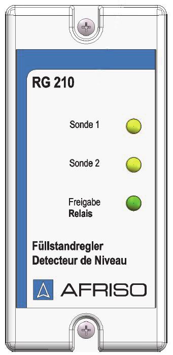
Über diese Betriebsanleitung                                    DE

1   Über diese Betriebsanleitung
    Diese Betriebsanleitung beschreibt den Füllstandregler RG 210 (im Folgen-
    den auch „Produkt“). Diese Betriebsanleitung ist Teil des Produkts.
    •   Sie dürfen das Produkt erst benutzen, wenn Sie die Betriebsanleitung
        vollständig gelesen und verstanden haben.
    •   Stellen Sie sicher, dass die Betriebsanleitung für alle Arbeiten an und mit
        dem Produkt jederzeit verfügbar ist.
    •   Geben Sie die Betriebsanleitung und alle zum Produkt gehörenden
        Unterlagen an alle Benutzer des Produkts weiter.
    •   Wenn Sie der Meinung sind, dass die Betriebsanleitung Fehler, Wider-
        sprüche oder Unklarheiten enthält, wenden Sie sich vor Benutzung des
        Produkts an den Hersteller.
    Diese Betriebsanleitung ist urheberrechtlich geschützt und darf ausschließ-
    lich im rechtlich zulässigen Rahmen verwendet werden. Änderungen vorbe-
    halten.
    Für Schäden und Folgeschäden, die durch Nichtbeachtung dieser Betriebs-
    anleitung sowie Nichtbeachten der am Einsatzort des Produkts geltenden
    Vorschriften, Bestimmungen und Normen entstehen, übernimmt der Herstel-
    ler keinerlei Haftung oder Gewährleistung.

                                                               RG 210             2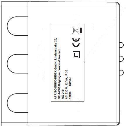
Informationen zur Sicherheit                                DE

2     Informationen zur Sicherheit
2.1   Warnhinweise und Gefahrenklassen
      In dieser Betriebsanleitung finden Sie Warnhinweise, die auf potenzielle
      Gefahren und Risiken aufmerksam machen. Zusätzlich zu den Anweisungen
      in dieser Betriebsanleitung müssen Sie alle am Einsatzort des Produktes
      geltenden Bestimmungen, Normen und Sicherheitsvorschriften beachten.
      Stellen Sie vor Verwendung des Produktes sicher, dass Ihnen alle Bestim-
      mungen, Normen und Sicherheitsvorschriften bekannt sind und dass sie
      befolgt werden.
      Warnhinweise sind in dieser Betriebsanleitung mit Warnsymbolen und Sig-
      nalwörtern gekennzeichnet. Abhängig von der Schwere einer Gefährdungs-
      situation werden Warnhinweise in unterschiedliche Gefahrenklassen unter-
      teilt.

                                      GEFAHR
      GEFAHR macht auf eine unmittelbar gefährliche Situation aufmerksam, die
      bei Nichtbeachtung unweigerlich einen schweren oder tödlichen Unfall zur
      Folge hat.

                                WARNUNG
      WARNUNG macht auf eine möglicherweise gefährliche Situation aufmerk-
      sam, die bei Nichtbeachtung einen schweren oder tödlichen Unfall oder
      Sachschäden zur Folge haben kann.

                                  HINWEIS
      HINWEIS macht auf eine möglicherweise gefährliche Situation aufmerksam,
      die bei Nichtbeachtung Sachschäden zur Folge haben kann.

                                                            RG 210            3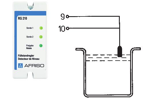
Informationen zur Sicherheit                                DE

Zusätzlich werden in dieser Betriebsanleitung folgende Symbole verwendet:
         Dies ist das allgemeine Warnsymbol. Es weist auf die
         Gefahr von Verletzungen und Sachschäden hin. Befolgen
         Sie alle im Zusammenhang mit diesem Warnsymbol
         beschriebenen Hinweise, um Unfälle mit Todesfolge, Verlet-
         zungen und Sachschäden zu vermeiden.

         Dieses Symbol warnt vor gefährlicher elektrischer Span-
         nung. Wenn dieses Symbol in einem Warnhinweis gezeigt
         wird, besteht die Gefahr eines elektrischen Schlags.

                                                       RG 210           4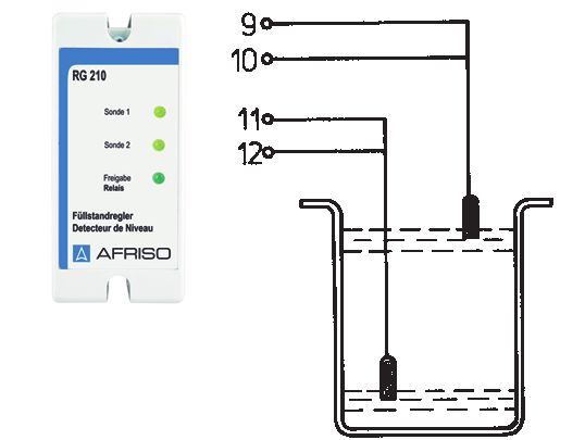
Informationen zur Sicherheit                                 DE

2.2   Bestimmungsgemäße Verwendung
      Dieses Produkt eignet sich ausschließlich als:
      •   Füllstandgrenzschalter
      •   Füllsteuerung
      •   Entnahmesteuerung
      Das Produkt eignet sich ausschließlich für folgende Medien:
      •   Heizöl EL, L oder M
      Eine andere Verwendung ist nicht bestimmungsgemäß und verursacht
      Gefahren.
      Stellen Sie vor Verwendung des Produkts sicher, dass das Produkt für die
      von Ihnen vorgesehene Verwendung geeignet ist. Berücksichtigen Sie dabei
      mindestens folgendes:
      •   Alle am Einsatzort geltenden Bestimmungen, Normen und Sicherheits-
          vorschriften
      •   Alle für das Produkt spezifizierten Bedingungen und Daten
      •   Die Bedingungen der von Ihnen vorgesehenen Anwendung
      Führen Sie darüber hinaus eine Risikobeurteilung in Bezug auf die konkrete,
      von Ihnen vorgesehene Anwendung nach einem anerkannten Verfahren
      durch und treffen Sie entsprechend dem Ergebnis alle erforderlichen Sicher-
      heitsmaßnahmen. Berücksichtigen Sie dabei auch die möglichen Folgen
      eines Einbaus oder einer Integration des Produkts in ein System oder in eine
      Anlage.
      Führen Sie bei der Verwendung des Produkts alle Arbeiten ausschließlich
      unter den in der Betriebsanleitung und auf dem Typenschild spezifizierten
      Bedingungen und innerhalb der spezifizierten technischen Daten und in
      Übereinstimmung mit allen am Einsatzort geltenden Bestimmungen, Nor-
      men und Sicherheitsvorschriften durch.

                                                               RG 210             5
Informationen zur Sicherheit DE
2.3 Vorhersehbare Fehlanwendung
Das Produkt darf insbesondere in folgenden Fällen und für folgende Zwecke
nicht angewendet werden:
• Flüssigkeiten, die zur Dickflüssigkeit neigen oder die zu Verklebungen
und festen Ablagerungen führen
• Flüssigkeiten mit Flammpunkt < 55 °C
• Feucht- und Nassräume
• Einsatz als Überfüllsicherung
• Explosionsgefährdete Umgebung
- Bei Betrieb in explosionsgefährdeten Bereichen kann Funkenbildung zu
Verpuffungen, Brand oder Explosionen führen.
Die Kaltleitersonde Typ 937 darf insbesondere in folgenden Fällen nicht ver-
wendet werden:
• Einsatz in korrosiven Medien
RG 210 6Informationen zur Sicherheit DE
2.4 Qualifikation des Personals
Montage, Inbetriebnahme, Wartung und Außerbetriebnahme dieses Pro-
dukts dürfen nur von einem qualifizierten Fachbetrieb vorgenommen werden,
der über eine entsprechende Zertifizierung verfügt und folgende Anforderun-
gen erfüllt:
• Einhaltung aller am Einsatzort des Produkts geltenden Bestimmungen,
Normen und Sicherheitsvorschriften zum Umgang mit wassergefährden-
den Stoffen.
• In Deutschland: Zertifizierung gemäß § 62 der Verordnung über Anlagen
zum Umgang mit wassergefährdenden Stoffen (AwSV).
Montage, Inbetriebnahme, Wartung und Außerbetriebnahme dieses Pro-
dukts dürfen nur von einer qualifizierten Elektrofachkraft (IEC 60050, IEV
195-4-1) vorgenommen werden. Die Elektrofachkraft (IEC 60050, IEV 195-4-
1) ist eine Person mit geeigneter fachlicher Ausbildung, Kenntnissen und
Erfahrung, so dass sie Gefahren erkennen und vermeiden kann, die von der
Elektrizität ausgehen können.
Arbeiten an und mit diesem Produkt dürfen nur von Fachkräften vorgenom-
men werden, die den Inhalt dieser Betriebsanleitung und alle zum Produkt
gehörenden Unterlagen kennen und verstehen.
Die Fachkräfte müssen aufgrund ihrer fachlichen Ausbildung, Kenntnisse
und Erfahrungen in der Lage sein, mögliche Gefährdungen vorherzusehen
und zu erkennen, die durch den Einsatz des Produkts entstehen können.
Den Fachkräften müssen alle geltenden Bestimmungen, Normen und
Sicherheitsvorschriften, die bei Arbeiten an und mit dem Produkt beachtet
werden müssen, bekannt sein.
Bei Heizölverbraucheranlagen
Montage, Inbetriebnahme, Wartung und Außerbetriebnahme dieses Pro-
dukts dürfen nur von einem qualifizierten Fachbetrieb vorgenommen werden,
der über eine entsprechende Zertifizierung verfügt und folgende Anforderun-
gen erfüllt:
• Einhaltung aller am Einsatzort des Produkts geltenden Bestimmungen,
Normen und Sicherheitsvorschriften zum Umgang mit wassergefährdenden
Stoffen.
• In Deutschland: Zertifizierung gemäß § 62 der Verordnung über Anlagen
zum Umgang mit wassergefährdenden Stoffen (AwSV).
RG 210 7Informationen zur Sicherheit DE
2.5 Persönliche Schutzausrüstung
Verwenden Sie immer die erforderliche persönliche Schutzausrüstung.
Berücksichtigen Sie bei Arbeiten an und mit dem Produkt auch, dass am Ein-
satzort Gefährdungen auftreten können, die nicht direkt vom Produkt ausge-
hen.
2.6 Veränderungen am Produkt
Führen Sie ausschließlich solche Arbeiten an und mit dem Produkt durch, die
in dieser Betriebsanleitung beschrieben sind. Nehmen Sie keine Verände-
rungen vor, die in dieser Betriebsanleitung nicht beschrieben sind.
RG 210 8Transport und Lagerung DE
3 Transport und Lagerung
Das Produkt kann durch unsachgemäßen Transport und Lagerung beschä-
digt werden.
HINWEIS
UNSACHGEMÄßE HANDHABUNG
• Stellen Sie sicher, dass während des Transports und der Lagerung des Pro-
dukts die spezifizierten Umgebungsbedingungen eingehalten werden.
• Benutzen Sie für den Transport die Originalverpackung.
• Lagern Sie das Produkt nur in trockener, sauberer Umgebung.
• Stellen Sie sicher, dass das Produkt bei Transport und Lagerung stoßge-
schützt ist.
Nichtbeachtung dieser Anweisungen kann zu Sachschäden führen.
RG 210 9Produktbeschreibung DE
4 Produktbeschreibung
Das Produkt darf nur mit der Kaltleitersonde Typ 937 betrieben werden. Die
Kaltleitersonde ist nicht im Lieferumfang des Produkts enthalten.
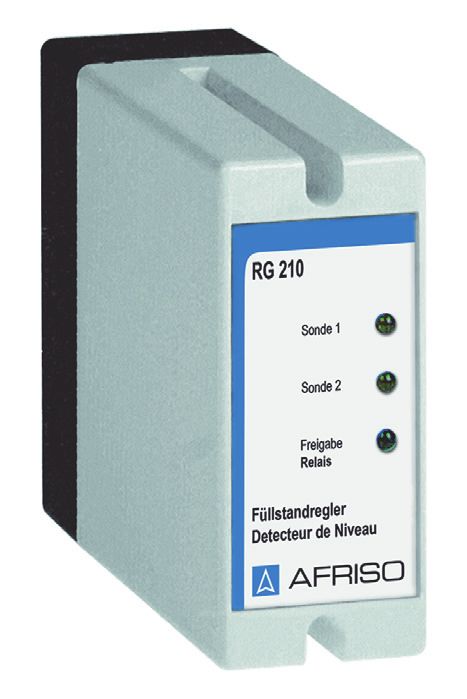
4.1 Füllstandregler
Der Füllstandregler enthält in einem schlagfesten Kunststoffgehäuse die
Anzeigeelemente, sowie sämtliche elektronische Komponenten zur Auswer-
tung und Umformung des Sondensignals in ein digitales Ausgangssignal.
Das Ausgangssignal steht als potenzialfreier Relaiskontakt (Wechsler) zur
Verfügung.
A. Gelbe LED „Sonde 1“ und
„Sonde 2“
B. Grüne LED
„Freigabe Relais“
A
B
E C. Gehäuseoberteil
C
D. Sockel
D
Abbildung 1: Füllstandregler
RG 210 10Produktbeschreibung DE
4.2 Kaltleitersonde Typ 937
Das Produkt und die Kaltleitersonde sind durch eine Signalleitung miteinan-
der verbunden.
Im Sondenkopf befindet sich ein Kaltleiter. Der Kaltleiter ist im Betrieb
erwärmt und kann auf Grund der unterschiedlichen Wärmeableitung zwi-
schen gasförmigen und flüssigen Medien unterscheiden.
Die Kaltleitersonde ist ein Verschleißteil. Sie muss spätestens nach zehn
Jahren erneuert werden.
A. Einschraubkörper G½ oder G1
B. Sondenkabel
A
C. Messinggewicht
D. Schutzhülse über dem Kaltleiter
B E. Kaltleiter
F. Schaltpunkt (Markierung)
C
D
F
Abbildung 2: Kaltleitersonde Typ 937
RG 210 11Produktbeschreibung DE
4.3 Abmessungen
113 mm
53 mm
RG 210 12Produktbeschreibung DE
4.4 Anwendungsbeispiel(e)
B
C
A
D
A. Pumpe Stopp C. Sonde 1
B. RG 210 D. Maximaler Füllstand
Abbildung 3: Einsatz als Füllstandgrenzschalter
RG 210 13Produktbeschreibung DE
B C
D
A
E
F
A. Pumpe an/aus D. Sonde 2
B. RG 210 E. Maximaler Füllstand
C. Sonde 1 F. Minimaler Füllstand
Abbildung 4: Einsatz als Füll-/Entnahmesteuerung
4.5 Lieferumfang
Im Lieferumfang sind enthalten:
• Füllstandregler RG 210
RG 210 14Produktbeschreibung DE
4.6 Funktion
Das Produkt wertet die Signale der Sonde/Sonden aus. Es eignet sich als
Füllstandgrenzschalter, Füllsteuerung oder als Entnahmesteuerung. Die
Betriebsart wird mit Hilfe eines Schiebeschalters auf der Leiterplatte einge-
stellt (siehe Kapitel "Betriebsart einstellen").
4.6.1 Betriebsart „Sonde 1“ (1 Sonde)
Das Produkt wird als Füllstandgrenzschalter eingesetzt. Es überwacht
das Ansteigen des Flüssigkeitspegels.
Wenn sich die Sonde in der Luft befindet, leuchtet die grüne LED.
Wenn die Flüssigkeit die Sonde erreicht, erlischt die grüne LED und die
gelbe LED leuchtet.
4.6.2 Betriebsart „ Füllen“ (2 Sonden)
Das Produkt wird als Füllsteuerung eingesetzt. Es überwacht das Anstei-
gen oder das Absinken des Flüssigkeitspegels mit 2 Sonden.
Wenn sich beide Sonden in einer Flüssigkeit befinden, leuchten die gel-
ben LEDs.
Wenn sich eine der Sonden in der Luft befindet, geht die gelbe LED der
betroffenen Sonde aus.
Wenn sich beide Sonden in der Luft befinden, leuchtet die grüne LED.
4.6.3 Betriebsart „Leeren“ (2 Sonden)
Das Produkt wird als Entnahmesteuerung eingesetzt. Es überwacht das
Ansteigen oder das Absinken des Flüssigkeitspegels mit 2 Sonden.
Wenn sich beide Sonden in einer Flüssigkeit befinden, leuchtet die grüne
LED.
Wenn sich eine der Sonden in der Luft befindet, geht die gelbe LED der
betroffenen Sonde an.
Wenn sich beide Sonden in der Luft befinden, ist die grüne LED aus.
RG 210 15Produktbeschreibung DE
4.7 Ausgangsrelais
Das Produkt verfügt über ein Ausgangsrelais zur Weiterleitung eines Signals
an zusätzliche Geräte.
Das Produkt kann mit und ohne Zusatzgeräte betrieben werden, beispiels-
weise:
• Optische und akustische Alarmgeber
• Fernmeldegeräte
• Gebäudeleittechnik
• Pumpen
• Ventile
4.8 Zulassungsdokumente, Bescheinigungen, Erklärungen
Das Produkt entspricht:
• EMV-Richtlinie (2014/30/EU)
• Niederspannungsrichtlinie (2014/35/EU)
• RoHS-Richtlinie (2011/65/EU)
RG 210 16Produktbeschreibung DE
4.9 Technische Daten
4.9.1 Füllstandregler
Parameter Wert
Allgemeine Daten
Abmessungen Gehäuse (B x H x T) 53 x 113 x 108 mm
Gewicht 550 g
Ansprechverzögerung Kleiner 2 s
Anzeige der Sondensignale 2 gelbe LEDs
Anzeige des Ausgangssignals 1 grüne LED
Ausgänge 1 Ausgangsrelais (Wechsler)
Anschlüsse für Kaltleitersonden 2
Umgebungsbedingungen
Umgebungstemperatur Betrieb -10 ... 55 °C
Umgebungstemperatur Lagerung -10 ... 60 °C
Versorgungsspannung AC 240 V
50 ... 60 Hz
Elektrische Daten
Nennleistung Max. 12 VA
Netzsicherung M 100 mA (5 x 20 mm)
Schaltvermögen Ausgangrelais Max. 250 V, 2 A
Elektrische Sicherheit (EN 61010)
Schutzklasse (EN 60730) II
Schutzart IP 30
Elektromagnetische Verträglichkeit (EMV)
Störaussendung EN 61000-6-3
Störfestigkeit EN 61000-6-1
RG 210 17Produktbeschreibung DE
4.9.2 Kaltleitersonde Typ 937 (nicht im Lieferumfang enthalten)
Parameter Wert
Allgemeine Daten
Abmessungen (Ø x L) 14 x 57 mm
Gewicht 130 g
Werkstoff Sondenkörper Kunststoff, G1a x G1/2a
Messinggewicht Messing, Ø x L = 14 x 30 mm
Sondengehäuse Kunststoff, Ø = 14 mm
Sondenelement Glasgekapselter Kaltleiter
Anschlusskabel Ölflex 2 x 0,5 mm2
Standardlänge 3m
Maximale Länge 50 m (geschirmt)
Aufheizzeit 8 ... 30 s, siehe Kapitel "Montage
vorbereiten"
Umgebungsbedingungen
Umgebungstemperatur Betrieb -25 ... 75 °C
Umgebungstemperatur Medium -25 ... 50 °C
Umgebungstemperatur Lagerung -25 ... 75 °C
Elektrische Daten
Sondenspannung Max. DC 12 V
Elektrische Sicherheit
Schutzart (EN 60529) IP 68
RG 210 18Montage DE
5 Montage
WARNUNG
HEISSE SONDENSPITZE
Die Sondenspitze kann Temperaturen bis über 100 °C erreichen.
• Stellen Sie sicher, dass Sie die Sondenspitze nicht berühren.
Nichtbeachtung dieser Anweisungen kann zu Tod, schweren Verletzun-
gen oder Sachschäden führen.
Beim Einschalten des Produkts beträgt die Aufheizzeit des Kaltleiters in der
Sonde bis zu 15 Sekunden. Erst nach Ablauf der Aufheizzeit ist das Produkt
betriebsbereit.
Wenn die Sonde aus einer Flüssigkeit gezogen wird, beträgt die Aufheizzeit
des Kaltleiters in der Sonde etwa 30 Sekunden. Erst nach Ablauf der Aufheiz-
zeit ist das Produkt betriebsbereit.
Berücksichtigen Sie diese Ansprechverzögerungen, wenn Sie die Höhe fest-
legen, in der die Sonde/Sonden montiert werden.
5.1 Montage vorbereiten
Stellen Sie sicher, dass das Produkt an eine ebene, feste und trockene
Wand in Augenhöhe montiert wird.
Stellen Sie sicher, dass die zulässige Umgebungstemperatur am Produkt
eingehalten wird.
Stellen Sie sicher, dass das Produkt jederzeit zugänglich und einsehbar
ist.
Stellen Sie sicher, dass das Produkt vor Wasser und Spritzwasser
geschützt ist.
RG 210 19Montage DE
5.2 Produkt montieren
5.2.1 Füllstandregler
1. Lösen Sie die zwei Gehäuseschrauben an der Vorderseite des Pro-
dukts.
2. Ziehen Sie das Gehäuseoberteil vom Sockel ab.
3. Befestigen Sie den Sockel an der Wand.
4. Schließen Sie das Produkt elektrisch an, siehe Kapitel "Elektrischer
Anschluss".
5. Stellen Sie die Betriebsart ein, siehe Kapitel "Betriebsart einstellen".
6. Setzen Sie das Gehäuseoberteil auf den Sockel.
- Stellen Sie sicher, dass die Kontaktleiste der Leiterplatte die Kontakt-
federn des Sockels nicht verbiegt.
7. Schrauben Sie das Gehäuseoberteil fest.
RG 210 20Montage DE
5.2.2 Sonde
HINWEIS
BESCHÄDIGUNG DER ANLAGE
• Stellen Sie sicher, dass bei der Montage keine Fremdkörper (zum Beispiel
Bohrspäne) in den Tank fallen.
Nichtbeachtung dieser Anweisungen kann zu Sachschäden führen.
Stellen Sie sicher, dass der Kaltleiter nicht von Flüssigkeitsspritzer aus-
gelöst werden kann.
Montage in einen Behälter
1. Lassen Sie die Kaltleitersonde am Kabel hängend in den Behälter hin-
unter.
2. Befestigen Sie das Kabel der Kaltleitersonde in der Höhe des
gewünschten Schaltpunktes.
Montage in einen Tank
1. Bohren Sie eine G1-Gewindebohrung am Behälterdeckel.
2. Ziehen Sie das Kabelende der Sonde durch das Gewicht und den Ein-
schraubkörper.
3. Stecken Sie die Kaltleitersonde mit Gewicht durch die Bohrung.
4. Schrauben Sie den Einschraubkörper G1 am Behälter ein.
5. Befestigen Sie das Kabel der Kaltleitersonde in der Höhe des
gewünschten Schaltpunktes.
RG 210 21Montage DE
5.3 Elektrischer Anschluss
GEFAHR
ELEKTRISCHER SCHLAG
• Stellen Sie sicher, dass durch die Art der elektrischen Installation der Schutz
gegen elektrischen Schlag (Schutzklasse, Schutzisolierung) nicht vermin-
dert wird.
Nichtbeachtung dieser Anweisungen führt zu Tod oder schweren Verlet-
zungen.
GEFAHR
ELEKTRISCHER SCHLAG DURCH SPANNUNGSFÜHRENDE TEILE
• Unterbrechen Sie vor Beginn der Arbeiten die Netzspannung und sichern
Sie diese gegen Wiedereinschalten.
• Stellen Sie sicher, dass durch elektrisch leitfähige Gegenstände oder
Medien keine Gefährdungen ausgehen können.
Nichtbeachtung dieser Anweisungen führt zu Tod oder schweren Verlet-
zungen.
HINWEIS
NICHTVERFÜGBARKEIT DER ÜBERWACHUNGSFUNKTION
• Installieren Sie keine Netzstecker oder Schalter in der Spannungsversor-
gung für das Produkt.
• Schalten Sie das Produkt nur über die bauseitige Netzsicherung ein und aus.
Nichtbeachtung dieser Anweisungen kann zu Sachschäden führen.
RG 210 22Montage DE
5.3.1 Spannungsversorgung
Stellen Sie sicher, dass der Netzanschluss des Produkts mit einer fest
verlegten, geeigneten Leitung (beispielsweise NYM-J 3 x 1,5 mm²)
montiert wird.
Stellen Sie sicher, dass die Zuleitung zum Produkt separat mit maximal
16 A abgesichert ist.
1. Führen Sie das Netzkabel durch die obere Gummitülle in das Produkt.
2. Schließen Sie die Phase an die Klemme L1 an.
3. Klemmen Sie N an.
4. Schließen Sie den Schutzleiter an die Klemme PE an.
RG 210 23Montage DE
A B C
D
B
E C
A. Freigabe D. Anschlussbild im Gehäuse
B. Sonde 1 E. Pumpe
C. Sonde 2
RG 210 24Montage DE
5.3.2 Kaltleitersonde anschließen
Verwenden Sie zur Verlängerung des Sondenkabels ein geschirmtes
Kabel mit 2 x 0,5 mm². Die maximale Länge der Sondenkabel beträgt
50 m.
Stellen Sie sicher, dass das Sondenkabel gegen Beschädigungen
geschützt wird (beispielsweise in Metallrohr verlegen).
Stellen Sie sicher, dass das Sondenkabel nicht direkt neben oder
zusammen mit Kabeln verlegt wird, die Netzspannung führen.
1. Führen Sie das Sondenkabel durch die unteren Gummitülle in das Pro-
dukt.
2. Schließen Sie die beiden Adern an die entsprechenden Klemmen mit
der Bezeichnung "Sonde 1"/"Sonde 2" an.
- Die Polarität ist beliebig.
5.3.3 Relaisausgang
Das Ausgangssignal des Produkts wird über einen potenzialfreien Relais-
kontakt (Wechsler) ausgegeben.
HINWEIS
SPANNUNGSSPITZEN BEIM ABSCHALTEN INDUKTIVER VERBRAUCHER
Spannungsspitzen beim Abschalten induktiver Verbraucher können negative
Auswirkungen auf elektrische Anlagen haben und zur Zerstörung des Schalt-
kontakts führen.
• Beschalten Sie induktive Verbraucher mit handelsüblichen RC-Kombinatio-
nen, beispielweise 0,1 µF/100 Ohm.
Nichtbeachtung dieser Anweisungen kann zu Sachschäden führen.
1. Verlegen Sie das Signalkabel fest.
2. Führen Sie das Signalkabel durch die mittlere Gummitülle in den
schwarzen Sockel.
3. Schließen Sie das Signalkabel an die entsprechenden Klemmen mit
der Bezeichnung "Freigabe" an.
RG 210 25Inbetriebnahme DE
6 Inbetriebnahme
Stellen Sie sicher, dass das Produkt ordnungsgemäß montiert und elekt-
risch angeschlossen wurde.
6.1 Betriebsart einstellen
Stellen Sie sicher, dass das Gehäuseoberteil vom Sockel abgeschraubt
ist.
B
C
D
E
A
A. Netzsicherung F1 D. Betriebsart „Füllen“
B. Schiebeschalter für Betriebsarten E. Betriebsart „Leeren“
C. Betriebsart „Sonde 1“
1. Lösen Sie mit einem kleinen Schraubendreher die graue Abdeckscheibe
aus dem Gehäuseoberteil.
2. Ziehen Sie die Leiterplatte aus dem Gehäuseoberteil.
3. Schalten Sie mit dem Schiebeschalter (B) die gewünschte Betriebsart
ein, siehe Kapitel "Funktion".
4. Setzen Sie die Leiterplatte wieder ein.
5. Schließen Sie das Produkt.
RG 210 26Betrieb DE
6.2 Produkt in Betrieb nehmen
Stellen Sie sicher, dass die gewünschte Betriebsart eingestellt ist, siehe
Kapitel "Betriebsart einstellen".
1. Schalten Sie die Spannungsversorgung über bauseitige Netzsicherung
ein.
- Der Aufheizvorgang der angeschlossenen Kaltleiter beginnt.
- Nach ungefähr 8 Sekunden sind die angeschlossenen Kaltleiter auf-
geheizt, sofern sie nicht in eine Flüssigkeit eingetaucht sind.
2. Führen Sie eine Funktionsprüfung durch, siehe Kapitel "Funktionsprü-
fung".
6.3 Funktionsprüfung
1. Tauchen Sie die Sonde/Sonden in die zu detektierende Flüssigkeit.
- Die gelben LEDs ändern ihren Schaltzustand.
2. Nehmen Sie die Sonde/Sonden aus der zu detektierende Flüssigkeit.
- Die gelben LEDs ändern ihren Schaltzustand.
3. Beobachten Sie die grüne LED und das Relais.
- Der Funktionsablauf muss der eingestellten Betriebsart entsprechen,
siehe Kapitel "Funktion".
7 Betrieb
Die Bedienung des Produkts beschränkt sich auf dessen regelmäßige Über-
wachung:
• Funktionsprüfung durchführen
• Sonden sind frei von Ablagerungen
7.1 Alarm
Über den Relaisausgang wird ein Signal an zusätzliche Geräte ausgegeben.
7.2 Ausfall der Versorgungsspannung
Bei Ausfall der Versorgungsspannung wird kein Alarm ausgelöst.
Beim Einschalten des Produkts beträgt die Aufheizzeit des Kaltleiters in der
Sonde bis zu 15 Sekunden. Erst nach Ablauf der Aufheizzeit ist das Produkt
betriebsbereit.
Wenn inzwischen der Minimalfüllstand oder der Maximalfüllstand erreicht
wurden, gibt das Produkt nach Wiederkehr der Versorgungsspannung
Alarm.
RG 210 27Wartung DE
8 Wartung
8.1 Wartungsintervalle
Zeitpunkt Tätigkeit
1 x monatlich Stellen Sie sicher, dass das Produkt und dessen
Umgebung stets sauber, zugänglich und einseh-
bar sind.
1 x jährlich und bei der Führen Sie eine Funktionsprüfung durch, siehe
Inbetriebnahme oder Kapitel "Funktionsprüfung".
nach Reparaturarbeiten
Prüfen Sie die Sonde/Sonden auf Beschädigun-
gen, Ablagerungen und Verschmutzungen.
Tauschen Sie die Sonde/Sonden bei Ablagerun-
gen aus.
Mindestens alle 10 Erneuern Sie die Sonde/Sonden.
Jahre
RG 210 28Wartung DE
8.2 Wartungstätigkeiten
GEFAHR
ELEKTRISCHER SCHLAG DURCH SPANNUNGSFÜHRENDE TEILE
• Unterbrechen Sie vor Beginn der Arbeiten die Netzspannung und sichern
Sie diese gegen Wiedereinschalten.
Nichtbeachtung dieser Anweisungen führt zu Tod oder schweren Verlet-
zungen.
Netzsicherung F1 tauschen
Stellen Sie sicher, dass die Netzspannung unterbrochen und gegen Wie-
dereinschalten gesichert ist.
1. Lösen Sie die Schrauben am Produkt.
2. Nehmen Sie das Gehäuseoberteil ab.
3. Lösen Sie die graue Abdeckscheibe aus dem Gehäuseoberteil.
4. Ziehen Sie die Leiterplatte aus dem Gehäuseoberteil.
5. Ersetzen Sie die Netzsicherung F1, siehe Kapitel "Betriebsart einstellen".
6. Schieben Sie die Leiterplatte in das Gehäuseoberteil.
7. Setzen Sie das Gehäuseoberteil auf den Sockel.
- Stellen Sie sicher, dass die Kontaktleiste der Leiterplatte die Kontakt-
federn des Sockels nicht verbiegt.
8. Schrauben Sie das Gehäuseoberteil fest.
9. Schalten Sie die Netzspannung ein.
RG 210 29Störungsbeseitigung DE
9 Störungsbeseitigung
Störungen, die nicht durch die im Kapitel beschriebenen Maßnahmen besei-
tigt werden können, dürfen nur durch den Hersteller oder Fachkräften beho-
ben werden.
Problem Mögliche Ursache Fehlerbehebung
Gelbe LEDs leuchten Versorgungsspan- Überprüfen Sie die Versor-
nicht nung fehlt gungsspannung
Netzsicherung Wechseln Sie die Netzsiche-
defekt rung aus, siehe Kapitel "War-
tungstätigkeiten"
Verdrahtung falsch Überprüfen Sie die Verdrah-
tung
Sonde/Sonden Überprüfen Sie die Sonde/
defekt Sonden
Grüne LED oder das falsche Betriebsart Überprüfen Sie die Betriebs-
Relais schaltet nicht eingestellt art, siehe Kapitel "Betriebs-
art einstellen"
Sonden vertauscht Schließen die Sonden kor-
rekt an
Produkt defekt Tauschen Sie das Produkt
Sonstige Störungen Bitte wenden Sie sich an die
AFRISO-Service Hotline
RG 210 30Außerbetriebnahme und Entsorgung DE
10 Außerbetriebnahme und Entsorgung
Entsorgen Sie das Produkt nach den geltenden Bestimmungen, Normen und
Sicherheitsvorschriften.
Elektronikteile dürfen nicht mit dem Hausmüll entsorgt werden.
1. Trennen Sie das Produkt von der Versorgungsspannung.
2. Demontieren Sie das Produkt (siehe Kapitel "Montage"
in umgekehrter Reihenfolge).
3. Entsorgen Sie das Produkt.
11 Rücksendung
Vor einer Rücksendung Ihres Produkts müssen Sie sich mit uns in Verbin-
dung setzen(service@afriso.de).
12 Gewährleistung
Informationen zur Gewährleistung finden Sie in unseren Allgemeinen
Geschäftsbedingungen im Internet unter www.afriso.com oder in Ihrem Kauf-
vertrag.
RG 210 31Ersatzteile und Zubehör DE
13 Ersatzteile und Zubehör
HINWEIS
UNGEEIGNETE TEILE
• Verwenden Sie nur Original Ersatz- und Zubehörteile des Herstellers.
Nichtbeachtung dieser Anweisung kann zu Sachschäden führen.
Produkt
Artikelbezeichnung Art.-Nr. Abbildung
Füllstandregler 53206
„RG 210“
Kaltleitersonde 53204
Typ 937
RG 210 32Operating
instructions
Level controller
Type: RG 210
For specialised companies only
Copyright 2021 AFRISO-EURO-INDEX GmbH. All rights reserved.
Lindenstraße 20
74363 Güglingen
Telephone +49 7135 102-0
Service +49 7135 102-211
Telefax +49 7135 102-147
info@afriso.com
Version: 02.2021.0
www.afriso.com
ID: 900.000.0149About these operating instructions EN
1 About these operating instructions
These operating instructions describe the level controller RG 210 (also
referred to as "product" in these operating instructions). These operating
instructions are part of the product.
• You may only use the product if you have fully read and understood these
operating instructions.
• Verify that these operating instructions are always accessible for any type
of work performed on or with the product.
• Pass these operating instructions as well as all other product-related doc-
uments on to all owners of the product.
• If you feel that these operating instructions contain errors, inconsisten-
cies, ambiguities or other issues, contact the manufacturer prior to using
the product.
These operating instructions are protected by copyright and may only be
used as provided for by the corresponding copyright legislation. We reserve
the right to modifications.
The manufacturer shall not be liable in any form whatsoever for direct or con-
sequential damage resulting from failure to observe these operating instruc-
tions or from failure to comply with directives, regulations and standards and
any other statutory requirements applicable at the installation site of the prod-
uct.
RG 210 2Information on safety EN
2 Information on safety
2.1 Safety messages and hazard categories
These operating instructions contain safety messages to alert you to poten-
tial hazards and risks. In addition to the instructions provided in these oper-
ating instructions, you must comply with all directives, standards and safety
regulations applicable at the installation site of the product. Verify that you are
familiar with all directives, standards and safety regulations and ensure com-
pliance with them prior to using the product.
Safety messages in these operating instructions are highlighted with warning
symbols and warning words. Depending on the severity of a hazard, the
safety messages are classified according to different hazard categories.
DANGER
DANGER indicates a hazardous situation, which, if not avoided, will result in
death or serious injury.
WARNING
WARNING indicates a potentially hazardous situation, which, if not avoided,
can result in serious injury or equipment damage.
NOTICE
NOTICE indicates a hazardous situation, which, if not avoided, can result in
equipment damage.
In addition, the following symbols are used in these operating instructions:
This is the general safety alert symbol. It alerts to injury haz-
ards or equipment damage. Comply with all safety instruc-
tions in conjunction with this symbol to help avoid possible
death, injury or equipment damage.
This symbol alerts to hazardous electrical voltage. If this
symbol is used in a safety message, there is a hazard of
electric shock.
RG 210 3Information on safety EN
2.2 Intended use
This product may only be used as:
• Level switch
• Level controller for filling
• Level controller for emptying
The product may only be used for the following media:
• Fuel oil EL, L or M
Any use other than the application explicitly permitted in these operating
instructions is not permitted and causes hazards.
Verify that the product is suitable for the application planned by you prior to
using the product. In doing so, take into account at least the following:
• All directives, standards and safety regulations applicable at the installa-
tion site of the product
• All conditions and data specified for the product
• The conditions of the planned application
In addition, perform a risk assessment in view of the planned application,
according to an approved risk assessment method, and implement the
appropriate safety measures, based on the results of the risk assessment.
Take into account the consequences of installing or integrating the product
into a system or a plant.
When using the product, perform all work and all other activities in conjunc-
tion with the product in compliance with the conditions specified in the oper-
ating instructions and on the nameplate, as well as with all directives, stand-
ards and safety regulations applicable at the installation site of the product.
RG 210 4Information on safety EN
2.3 Predictable incorrect application
The product must never be used in the following cases and for the following
purposes:
• Liquids which tend to become highly viscous or lead to agglutinations or
deposits
• Liquids with a flash point of < 55 °C
• Damp, humid, wet rooms
• Use as overfill prevention system
• Hazardous area (EX)
- If the product is operated in hazardous areas, sparks may cause defla-
grations, fires or explosions.
The PTC thermistor probe type 937 must never be used in the following
cases:
• Use with corrosive media
RG 210 5Information on safety EN
2.4 Qualification of personnel
This product may only be mounted, commissioned, maintained and decom-
missioned by a qualified, specialised company which has all required certifi-
cations and which meets the following requirements:
• Compliance with all directives, standards and safety regulations concern-
ing handling of water-polluting substances as applicable at the installation
site of the product.
• In Germany: Certification as per § 62 "Verordnung über Anlagen zum
Umgang mit wassergefährdenden Stoffen" (AwSV) (Ordinance on Instal-
lations for Handling Water-Polluting Substances).
This product may only be mounted, commissioned, maintained and decom-
missioned by an electrically skilled person (IEC 60050, IEV 195-4-1). An
electrically skilled person (IEC 60050, IEV 195-4-1) is person with relevant
education and experience to enable him or her to perceive risks and to avoid
hazards which electricity can create.
Only appropriately trained persons who are familiar with and understand the
contents of these operating instructions and all other pertinent product doc-
umentation are authorized to work on and with this product.
These persons must have sufficient technical training, knowledge and expe-
rience and be able to foresee and detect potential hazards that may be
caused by using the product.
All persons working on and with the product must be fully familiar with all
directives, standards and safety regulations that must be observed for per-
forming such work.
In the case of fuel oil consuming systems
This product may only be mounted, commissioned, maintained and decom-
missioned by a qualified, specialised company which has all required certifi-
cations and which meets the following requirements:
• Compliance with all directives, standards and safety regulations concerning
handling of water-polluting substances as applicable at the installation site of
the product.
• In Germany: Certification as per § 62 "Verordnung über Anlagen zum
Umgang mit wassergefährdenden Stoffen" (AwSV) (Ordinance on Installa-
tions for Handling Water-Polluting Substances).
RG 210 6Information on safety EN
2.5 Personal protective equipment
Always wear the required personal protective equipment. When performing
work on and with the product, take into account that hazards may be present
at the installation site which do not directly result from the product itself.
2.6 Modifications to the product
Only perform work on and with the product which is explicitly described in
these operating instructions. Do not make any modifications to the product
which are not described in these operating instructions.
RG 210 7Transport and storage EN
3 Transport and storage
The product may be damaged as a result of improper transport or storage.
NOTICE
INCORRECT HANDLING
• Verify compliance with the specified ambient conditions during transport or
storage of the product.
• Use the original packaging when transporting the product.
• Store the product in a clean and dry environment.
• Verify that the product is protected against shocks and impact during trans-
port and storage.
Failure to follow these instructions can result in equipment damage.
RG 210 8Product description EN
4 Product description
The product may only be operated with the PTC thermistor probe type 937.
The PTC thermistor probe is not included in the scope of delivery of the prod-
uct.
4.1 Level controllers
The level controller contains the following elements in an impact-resistant
plastic housing: display elements as well as all electronic components for sig-
nal processing and conversion of the probe signal into a digital output signal.
The output signal is available as a voltage-free relay contact (changeover
contact).
A. Yellow LEDs "Probe 1" and
"Probe 2" ("Sonde 1" and
"Sonde 2")
B. Green LED "Release
A Relay" ("Freigabe Relais")
B
C C. Upper part of housing
D. Base
D
Fig. 1: Level controllers
RG 210 9Product description EN
4.2 PTC thermistor probe type 937
The product and the PTC thermistor probe are connected by means of a sig-
nal cable.
A PTC thermistor is contained in the probe head. During operation, the PTC
thermistor is heated and can distinguish between gaseous and liquid media
due to the different heat dissipation.
The PTC thermistor probe is a wearing part. It must be replaced after no
more than ten years.
A. Screw fitting G½ or G1
B. Probe cable
A
C. Brass weight
D. Protective sleeve for PTC thermis-
tor
B
E. PTC thermistor
F. Switching point (mark)
C
D
E
F
Fig. 2: PTC thermistor probe type 937
RG 210 10Product description EN
4.3 Dimensions
113 mm
53 mm
RG 210 11Product description EN
4.4 Application example(s)
B
C
A
D
A. Pump stop C. Probe 1
B. RG 210 D. Maximum level
Fig. 3: Use as level switch
RG 210 12Product description EN
B C
D
A
E
F
A. Pump on/off D. Probe 2
B. RG 210 E. Maximum level
C. Probe 1 F. Minimum level
Fig. 4: Use as level controller for filling/emptying
4.5 Scope of delivery
The scope of delivery includes:
• Level controller RG 210
RG 210 13Product description EN
4.6 Function
The product evaluates the signals received from the probe/probes. It be used
as a level switch, level controller for filling or level controller for emptying. The
operating mode is set by means of a slide switch on the printed circuit board
(see chapter "Setting the operating mode").
4.6.1 Operating mode "Probe 1" (1 probe)
The product is used as a level switch. It monitors a rising level of the liquid.
If the probe is in air, the green LED is lit.
If the liquid reaches the probe, the green LED turns off and the yellow LED
is lit.
4.6.2 Operating mode "Filling" (2 probes)
The product is as a level controller for filling. It monitors a rising and falling
level of the liquid with 2 probes.
If both probes are in a liquid, the yellow LEDs are lit.
If one of the probes is in air, the yellow LED of this probe turns off.
If both probes are in air, the green LED is lit.
4.6.3 Operating mode "Emptying" (2 probes)
The product is used as a level controller for emptying. It monitors a rising
and falling level of the liquid with 2 probes.
If both probes are in a liquid, the green LED is lit.
If one of the probes is in air, the yellow LED of this probe is lit.
If both probes are in air, the green LED is off.
RG 210 14Product description EN
4.7 Output relay
The product is equipped with an output relay to transmit a signal to additional
equipment.
The product can be operated with or without additional external equipment,
for example:
• Visual and audible alarm units
• Remote alarm equipment
• Building control systems
• Pumps
• Valves
4.8 Approvals, conformities, certifications
The product complies with:
• EMC Directive (2014/30/EU)
• Low Voltage Directive (2014/35/EU)
• RoHS Directive (2011/65/EU)
RG 210 15Product description EN
4.9 Technical data
4.9.1 Level controllers
Parameter Value
General specifications
Dimensions housing (W x H x D) 53 x 113 x 108 mm
Weight 550 g
Response delay Less than 2 s
Indication of probe signals 2 yellow LEDs
Indication of output signal 1 green LED
Outputs 1 output relay (changeover contact)
Connections for PTC thermistor probes 2
Ambient conditions
Ambient temperature operation -10 ... 55 °C
Ambient temperature storage -10 ... 60 °C
Supply voltage AC 240 V
50 ... 60 Hz
Electrical data
Nominal power Max. 12 VA
Mains fuse M 100 mA (5 x 20 mm)
Breaking capacity output relay Max. 250 V, 2 A
Electrical safety (EN 61010)
Protection class (EN 60730) II
Degree of protection IP 30
Electromagnetic compatibility (EMC)
Emitted interference EN 61000-6-3
Noise immunity EN 61000-6-1
RG 210 16Product description EN
4.9.2 PTC thermistor probe type 937 (not included in scope of deliv-
ery)
Parameter Value
General specifications
Dimensions (Ø x L) 14 x 57 mm
Weight 130 g
Material probe body Plastic, G1 male x G1/2 male
Brass weight Brass, Ø x L = 14 x 30 mm
Probe housing Plastic, Ø = 14 mm
Probe element Glass-encapsulated PTC thermis-
tor
Connection cable Ölflex 2 x 0.5 mm2
Standard length 3m
Maximum length 50 m (shielded)
Heat-up time 8 ... 30 s, see chapter "Preparing
mounting"
Ambient conditions
Ambient temperature operation -25 ... 75 °C
Ambient temperature medium -25 ... 50 °C
Ambient temperature storage -25 ... 75 °C
Electrical data
Probe voltage Max. DC 12 V
Electrical safety
Degree of protection (EN 60529) IP 68
RG 210 17Mounting EN
5 Mounting
WARNING
HOT PROBE TIP
The probe tip can reach temperatures of more than 100°C.
• Avoid any contact with the probe tip.
Failure to follow these instructions can result in death, serious injury or
equipment damage.
When the product is switched on, the heat-up time of the PTC thermistor is
up to 15 seconds. This heat-up time must elapse before the product is ready
for operation.
When the probe is pulled out of a liquid, the heat-up time of the PTC thermis-
tor is approximately 30 seconds. This heat-up time must elapse before the
product is ready for operation.
Consider these response delays when selecting the height at which the
probe is/probes are to be mounted.
5.1 Preparing mounting
Verify that the product is mounted to an even, rigid and dry wall at eye
level.
Verify that the permissible ambient temperature is respected at the prod-
uct.
Verify that the product is accessible and easy to oversee at all times.
Verify that the product is protected against water and splash water.
RG 210 18Mounting EN
5.2 Mounting the product
5.2.1 Level controllers
1. Loosen the two housing screws at the front of the product.
2. Remove the upper part of the housing from the base.
3. Mount the base to the wall.
4. Connect the product electrically, see chapter "Electrical connection".
5. Select the operating mode, see chapter "Setting the operating mode".
6. Fit the upper part of the housing to the base.
- Verify that the contact bar of the printed circuit board does not damage
the contact springs of the base.
7. Mount the upper part of the housing with the screws.
RG 210 19Mounting EN
5.2.2 Probe
NOTICE
DAMAGE TO THE SYSTEM
• Verify that no foreign matter (such as drilling chips) can get into the tank dur-
ing mounting.
Failure to follow these instructions can result in equipment damage.
Verify that the PTC thermistor cannot be triggered by splashes of the
liquid.
Mounting in a container
1. Suspend the PTC thermistor probe into the container at the cable.
2. Fasten the cable of the PTC thermistor probe at the height of the
desired switching point.
Mounting in a tank
1. Drill a G1 threaded hole at the tank cover.
2. Pull the cable end of the probe through the weight and the screw fitting.
3. Insert the PTC thermistor probe with weight through the hole.
4. Screw in the screw fitting G1 at the container.
5. Fasten the cable of the PTC thermistor probe at the height of the
desired switching point.
RG 210 20Mounting EN
5.3 Electrical connection
DANGER
ELECTRIC SHOCK
• Verify that the degree of protection against electric shock (protection class,
double insulation) is not reduced by the type of electrical installation.
Failure to follow these instructions will result in death or serious injury.
DANGER
ELECTRIC SHOCK CAUSED BY LIVE PARTS
• Disconnect the mains voltage supply before performing the work and ensure
that it cannot be switched on.
• Verify that no hazards can be caused by electrically conductive objects or
media.
Failure to follow these instructions will result in death or serious injury.
NOTICE
UNAVAILABLE MONITORING FUNCTION
• Do not install mains plugs or switches in the supply line to the product.
• Only power on/power off the product via the on-site mains fuse.
Failure to follow these instructions can result in equipment damage.
RG 210 21Mounting EN
5.3.1 Supply voltage
Verify that the product is connected to mains by means of a suitable,
permanently installed cable (for example NYM-J 3 x 1.5 mm²).
Verify that the power supply to the control unit is separately fused (16 A
maximum).
1. Route the mains cable through the upper rubber piece into the product.
2. Connect the phase to terminal L1.
3. Connect N.
4. Connect the protective conductor to terminal PE.
RG 210 22Mounting EN
A B C
D
B
E C
A. Release D. Wiring diagram in housing
B. Probe 1 E. Pump
C. Probe 2
RG 210 23Mounting EN
5.3.2 Connecting the PTC thermistor probe
Use a shielded cable with 2 x 0.5 mm² to extend the probe cable. The
maximum length of the probe cables is 50 m.
Verify that the probe cable is sufficiently protected from damage, for
example by installing it in a metal pipe.
Verify that the probe cable is not routed immediately next to or together
with cables carrying mains voltage.
1. Route the probe cable through the bottom rubber piece into the prod-
uct.
2. Connect the two wires to the appropriate terminal with the designation
"Probe 1"/"Probe 2".
- Any polarity is permissible.
5.3.3 Relay output
The output signal of the product is made available via a voltage-free relay
contact (changeover contact).
NOTICE
VOLTAGE PEAKS WHEN INDUCTIVE CONSUMERS ARE SWITCHED OFF
When inductive consumers are switched off, this can cause voltage peaks and
can lead to adverse effects on electrical systems and may destroy the switching
contact.
• Use commercially available standard RC combinations such as 0.1 µF/
100 Ohm for inductive consumers.
Failure to follow these instructions can result in equipment damage.
1. The signal cable requires permanent installation.
2. Route the signal cable through the centre rubber piece into the black
base.
3. Connect the signal cable to the appropriate terminals with the designa-
tion "Freigabe" ("Release").
RG 210 24Commissioning EN
6 Commissioning
Verify that the product has been properly mounted and electrically con-
nected.
6.1 Setting the operating mode
Verify that the upper part of the housing has been removed from the base.
B
C
D
E
A
A. Mains fuse F1 D. Operating mode "Filling"
B. Slide switch for operating modes E. Operating mode "Emptying"
C. Operating mode "Probe 1"
1. Loosen the grey cover from the upper part of the housing by means of a
small screwdriver.
2. Pull the printed circuit board out of the upper part of the housing.
3. Se the desired operating mode with the slide switch (B), see chapter
"Function".
4. Refit the printed circuit board.
5. Close the product.
RG 210 25Operation EN
6.2 Commissioning the product
Verify that the required operating mode has been set, see chapter "Setting
the operating mode".
1. Switch on the power supply via the on-site mains fuse.
- The connected PTC thermistors heat up.
- The connected PTC thermistors are heated up after approximately 8
seconds, provided they are not submerged in liquid.
2. Perform a function test, see chapter "Function test".
6.3 Function test
1. Submerge the probe(s) into liquid to be detected.
- The yellow LEDs change their switching state.
2. Remove the probe(s) from the liquid to be detected.
- The yellow LEDs change their switching state.
3. Observe the green LED and the relay.
- The function sequence must correspond to the set operating mode, see
chapter "Function".
7 Operation
Operating the product is limited to its regular monitoring:
• Performing the function test
• Probes are free from deposits
7.1 Alarm
A signal is transmitted to additional equipment via the relay output.
7.2 Power outage
No alarm is triggered in case of a power outage.
When the product is switched on, the heat-up time of the PTC thermistor is
up to 15 seconds. This heat-up time must elapse before the product is ready
for operation.
If, during the power outage, the minimum level or the maximum level have
been reached, the product triggers an alarm once power is available again.
RG 210 26Maintenance EN
8 Maintenance
8.1 Maintenance intervals
When Activity
Monthly Verify that the product and its environment are
always clean, accessible and easy to oversee.
Once per year and dur- Perform a function test, see chapter "Function
ing commissioning or test".
after after repair work
Verify that the probe(s) are free from damage,
deposits and pollution.
Replace the probe(s) if you detect deposits.
At least every 10 years Replace the probe(s).
RG 210 27Maintenance EN
8.2 Maintenance activities
DANGER
ELECTRIC SHOCK CAUSED BY LIVE PARTS
• Disconnect the mains voltage supply before performing the work and ensure
that it cannot be switched on.
Failure to follow these instructions will result in death or serious injury.
Replacing the mains fuse F1
Verify that the mains voltage is interrupted and cannot be switched on.
1. Loosen the screws at the product.
2. Remove the upper part of the housing.
3. Remove the grey cover from the upper part of the housing.
4. Pull the printed circuit board out of the upper part of the housing.
5. Replace the mains fuse F1, see chapter "Setting the operating mode".
6. Push the printed circuit board into the upper part of the housing.
7. Fit the upper part of the housing to the base.
- Verify that the contact bar of the printed circuit board does not damage
the contact springs of the base.
8. Mount the upper part of the housing with the screws.
9. Apply mains voltage.
RG 210 28Troubleshooting EN
9 Troubleshooting
Any malfunctions that cannot be removed by means of the measures
described in this chapter may only be repaired by the manufacturer or by
qualified persons.
Problem Possible reason Repair
Yellow LEDs do not light No supply voltage Check the power supply
Mains fuse defective Replace the mains fuse, see
chapter "Maintenance activi-
ties"
Incorrect wiring Verify correct wiring
Probe(s) defective Check the probe(s)
Green LED and the incorrect operating Check the operating mode,
relay do not switch mode selected see chapter "Setting the
operating mode"
Probes inter- Properly connect the probes
changed
Product defective Replace the product
Other malfunctions Contact the AFRISO service
hotline
RG 210 29Decommissioning, disposal EN
10 Decommissioning, disposal
Dispose of the product in compliance with all applicable directives, standards
and safety regulations.
Electronic components must not be disposed of together with the normal
household waste.
1. Disconnect the product from mains.
2. Dismount the product (see chapter "Mounting", reverse
sequence of steps).
3. Dispose of the product.
11 Returning the device
Get in touch with us before returning your product (service@afriso.de).
12 Warranty
See our terms and conditions at www.afriso.com or your purchase contract
for information on warranty.
RG 210 30Spare parts and accessories EN
13 Spare parts and accessories
NOTICE
UNSUITABLE PARTS
• Only use genuine spare parts and accessories provided by the manufac-
turer.
Failure to follow these instructions can result in equipment damage.
Product
Product designation Part no. Figure
Level controller 53206
"RG 210"
PTC thermistor probe 53204
type 937
RG 210 31Notice technique
Régulateur de niveau
Type : RG 210
Seulement pour les entreprises spécialisées
Copyright 2021 AFRISO-EURO-INDEX GmbH. Tous droits réservés.
Lindenstraße 20
74363 Güglingen Téléphone +49 7135 102-0
Service clientèle +49 7135 102-211
Téléfax +49 7135 102-147
info@afriso.com
Version: 02.2021.0
ID: 900.000.0149La présente notice technique FR
1 La présente notice technique
Cette notice technique contient la description du régulateur de niveau
RG 210 (dénommé ci-après "produit"). Cette notice technique fait partie du
produit.
• Utilisez le produit seulement après que vous aurez lu et compris intégra-
lement la notice technique.
• Assurez-vous que la notice technique est disponible en permanence pour
toutes les opérations relatives au produit.
• Transmettez la notice technique et toute la documentation relative au pro-
duit à tous les utilisateurs du produit.
• Si vous êtes d'avis que la notice technique contient des erreurs, des
contradictions ou des ambiguïtés, adressez-vous au fabricant avant d'uti-
liser le produit.
Cette notice technique est protégée au titre de la propriété intellectuelle ; elle
doit être utilisée exclusivement dans le cadre autorisé par la loi. Sous réserve
de modifications.
La responsabilité du fabricant ou la garantie ne pourra être engagée pour des
dommages ou dommages consécutifs résultant d'une inobservation de cette
notice technique ou des directives, règlements et normes en vigueur sur le
lieu d'installation du produit.
RG 210 2Informations sur la sécurité FR
2 Informations sur la sécurité
2.1 Consignes de sécurité et classes de risques
Cette notice technique contient des consignes de sécurité destinées à attirer
l'attention sur les dangers et les risques. Outre les instructions contenues
dans cette notice technique, il faut vous assurer de l'observation de tous les
règlements, normes et consignes de sécurité en vigueur sur le lieu d'instal-
lation du produit. Avant d'utiliser le produit assurez-vous que tous les règle-
ments, normes et consignes de sécurité sont connus et respectés.
Dans cette notice technique les consignes de sécurité sont identifiables à
l'aide de symboles de mise en garde et de mots d'avertissement. En fonction
de la gravité du risque les consignes de sécurité sont réparties dans diffé-
rentes classes de risques.
DANGER
DANGER signale une situation directement dangereuse qui, si elle n'est pas
évitée, entraîne la mort ou des blessures graves.
AVERTISSEMENT
AVERTISSEMENT signale une situation potentiellement dangereuse qui, si
elle n'est pas évitée, peut entraîner la mort ou des blessures graves ou un
dommage matériel.
AVIS
AVIS signale une situation potentiellement dangereuse qui, si elle n'est pas
évitée, peut entraîner un dommage matériel.
RG 210 3Sie können auch lesen