Betriebsanleitung Manometer-Druckknopfhahn - Afriso
←
→
Transkription von Seiteninhalten
Wenn Ihr Browser die Seite nicht korrekt rendert, bitte, lesen Sie den Inhalt der Seite unten
Betriebsanleitung
Manometer-Druckknopfhahn
Copyright 2020 AFRISO-EURO-INDEX GmbH. Alle Rechte vorbehalten.
Lindenstraße 20
74363 Güglingen
Telefon +49 7135 102-0
Service +49 7135 102-211
Telefax +49 7135 102-147
info@afriso.com
Version: 03.2020.0
www.afriso.com
ID: 900.000.0220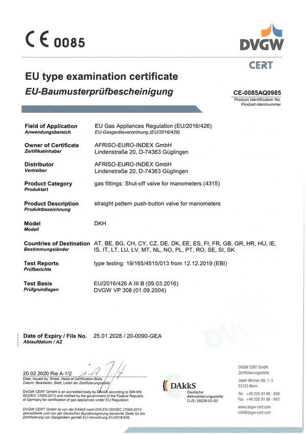
Über diese Betriebsanleitung                                     DE

1   Über diese Betriebsanleitung
    Diese Betriebsanleitung beschreibt den Manometer-Druckknopfhahn (im
    Folgenden auch „Produkt“). Diese Betriebsanleitung ist Teil des Produkts.
    •   Sie dürfen das Produkt erst benutzen, wenn Sie die Betriebsanleitung
        vollständig gelesen und verstanden haben.
    •   Stellen Sie sicher, dass die Betriebsanleitung für alle Arbeiten an und mit
        dem Produkt jederzeit verfügbar ist.
    •   Geben Sie die Betriebsanleitung und alle zum Produkt gehörenden Unter-
        lagen an alle Benutzer des Produkts weiter.
    •   Wenn Sie der Meinung sind, dass die Betriebsanleitung Fehler, Wider-
        sprüche oder Unklarheiten enthält, wenden Sie sich vor Benutzung des
        Produkts an den Hersteller.
    Diese Betriebsanleitung ist urheberrechtlich geschützt und darf ausschließ-
    lich im rechtlich zulässigen Rahmen verwendet werden. Änderungen vorbe-
    halten.
    Für Schäden und Folgeschäden, die durch Nichtbeachtung dieser Betriebs-
    anleitung sowie Nichtbeachten der am Einsatzort des Produkts geltenden
    Vorschriften, Bestimmungen und Normen entstehen, übernimmt der Herstel-
    ler keinerlei Haftung oder Gewährleistung.

                                              Manometer-Druckknopfhahn            2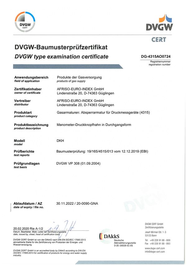
Informationen zur Sicherheit                                  DE

2     Informationen zur Sicherheit
2.1   Warnhinweise und Gefahrenklassen
      In dieser Betriebsanleitung finden Sie Warnhinweise, die auf potenzielle
      Gefahren und Risiken aufmerksam machen. Zusätzlich zu den Anweisungen
      in dieser Betriebsanleitung müssen Sie alle am Einsatzort des Produktes gel-
      tenden Bestimmungen, Normen und Sicherheitsvorschriften beachten. Stel-
      len Sie vor Verwendung des Produktes sicher, dass Ihnen alle Bestimmun-
      gen, Normen und Sicherheitsvorschriften bekannt sind und dass sie befolgt
      werden.
      Warnhinweise sind in dieser Betriebsanleitung mit Warnsymbolen und Sig-
      nalwörtern gekennzeichnet. Abhängig von der Schwere einer Gefährdungs-
      situation werden Warnhinweise in unterschiedliche Gefahrenklassen unter-
      teilt.

                                  WARNUNG
      WARNUNG macht auf eine möglicherweise gefährliche Situation aufmerk-
      sam, die bei Nichtbeachtung einen schweren oder tödlichen Unfall oder
      Sachschäden zur Folge haben kann.

                                   HINWEIS
      HINWEIS macht auf eine möglicherweise gefährliche Situation aufmerksam,
      die bei Nichtbeachtung Sachschäden zur Folge haben kann.

      Zusätzlich werden in dieser Betriebsanleitung folgende Symbole verwendet:
                      Dies ist das allgemeine Warnsymbol. Es weist auf die
                      Gefahr von Verletzungen und Sachschäden hin. Befolgen
                      Sie alle im Zusammenhang mit diesem Warnsymbol
                      beschriebenen Hinweise, um Unfälle mit Todesfolge, Verlet-
                      zungen und Sachschäden zu vermeiden.

                                              Manometer-Druckknopfhahn           3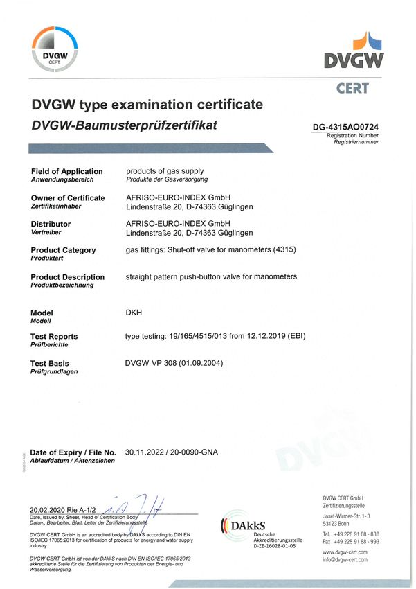
Informationen zur Sicherheit                                DE

2.2   Bestimmungsgemäße Verwendung
      Dieses Produkt eignet sich ausschließlich als Absperrorgan zwischen Mess-
      leitung und Manometer und ist für Gase (nach DVGW G260 und SVGW)
      geeignet.
      Eine andere Verwendung ist nicht bestimmungsgemäß und verursacht
      Gefahren.
      Stellen Sie vor Verwendung des Produkts sicher, dass das Produkt für die
      von Ihnen vorgesehene Verwendung geeignet ist. Berücksichtigen Sie dabei
      mindestens folgendes:
      •   Alle am Einsatzort geltenden Bestimmungen, Normen und Sicherheits-
          vorschriften
      •   Alle für das Produkt spezifizierten Bedingungen und Daten
      •   Die Bedingungen der von Ihnen vorgesehenen Anwendung
      Führen Sie darüber hinaus eine Risikobeurteilung in Bezug auf die konkrete,
      von Ihnen vorgesehene Anwendung nach einem anerkannten Verfahren
      durch und treffen Sie entsprechende dem Ergebnis alle erforderlichen
      Sicherheitsmaßnahmen. Berücksichtigen Sie dabei auch die möglichen Fol-
      gen eines Einbaus oder einer Integration des Produkts in ein System oder in
      eine Anlage.
      Führen Sie bei der Verwendung des Produkts alle Arbeiten ausschließlich
      unter den in der Betriebsanleitung und auf dem Typenschild spezifizierten
      Bedingungen und innerhalb der spezifizierten technischen Daten und in
      Übereinstimmung mit allen am Einsatzort geltenden Bestimmungen, Normen
      und Sicherheitsvorschriften durch.

2.3   Vorhersehbare Fehlanwendung
      Das Produkt darf insbesondere in folgenden Fällen und für folgende Zwecke
      nicht angewendet werden:
      •   Flüssigkeiten
      •   Andere Gase
      •   In nicht ausreichend belüfteten Räumen

                                              Manometer-Druckknopfhahn          4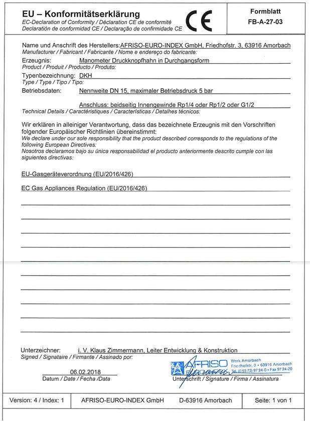
Informationen zur Sicherheit                                 DE

2.4   Qualifikation des Personals
      Arbeiten an und mit diesem Produkt dürfen nur von Fachkräften vorgenom-
      men werden, die den Inhalt dieser Betriebsanleitung und alle zum Produkt
      gehörenden Unterlagen kennen und verstehen.
      Die Fachkräfte müssen aufgrund ihrer fachlichen Ausbildung, Kenntnisse
      und Erfahrungen in der Lage sein, mögliche Gefährdungen vorherzusehen
      und zu erkennen, die durch den Einsatz des Produkts entstehen können.
      Den Fachkräften müssen alle geltenden Bestimmungen, Normen und
      Sicherheitsvorschriften, die bei Arbeiten an und mit dem Produkt beachtet
      werden müssen, bekannt sein.

2.5   Persönliche Schutzausrüstung
      Verwenden Sie immer die erforderliche persönliche Schutzausrüstung.
      Berücksichtigen Sie bei Arbeiten an und mit dem Produkt auch, dass am Ein-
      satzort Gefährdungen auftreten können, die nicht direkt vom Produkt ausge-
      hen.

2.6   Veränderungen am Produkt
      Führen Sie ausschließlich solche Arbeiten an und mit dem Produkt durch, die
      in dieser Betriebsanleitung beschrieben sind. Nehmen Sie keine Verände-
      rungen vor, die in dieser Betriebsanleitung nicht beschrieben sind.

                                              Manometer-Druckknopfhahn            5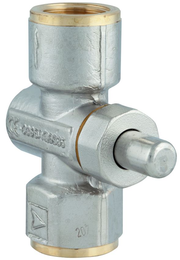
Transport und Lagerung                                  DE

3     Transport und Lagerung
      Das Produkt kann durch unsachgemäßen Transport und Lagerung beschä-
      digt werden.

                                   HINWEIS
    UNSACHGEMÄSSE HANDHABUNG
    • Stellen Sie sicher, dass während des Transports und der Lagerung des Pro-
      dukts die spezifizierten Umgebungsbedingungen eingehalten werden.
    • Benutzen Sie für den Transport die Originalverpackung.
    • Lagern Sie das Produkt nur in trockener, sauberer Umgebung.
    • Stellen Sie sicher, dass das Produkt bei Transport und Lagerung stoßge-
      schützt ist.
    Nichtbeachtung dieser Anweisungen kann zu Sachschäden führen.

                                             Manometer-Druckknopfhahn         6
Produktbeschreibung DE
4 Produktbeschreibung
4.1 Produktidentifikation
Zur Identifikation Ihres Produkts dient die Gravur.
A. CE-Kennzeichnung gemäß Gas-
geräteverordnung EU/2016/426
A
Manometer-Druckknopfhahn 7Produktbeschreibung DE
4.2 Übersicht
A A. Manometer
B. Druckknopfhahn
C. Druck anzeigen
D. Druck entlasten
E. Zuleitung
B
C
D
E
Manometer-Druckknopfhahn 8Produktbeschreibung DE
4.3 Abmessungen
64 mm
A. Rp½; G½
A B. Rp½; G½
71,5 (Rp½) / 73,5 (G½)
B
Abbildung 1: Abmessungen und Anschlüsse (Rp ½; G ½)
64 mm A. Rp¼; G¼
A B. Rp¼; G¼
53,5 mm
B
Abbildung 2: Abmessungen und Anschlüsse (Rp¼; G¼)
Manometer-Druckknopfhahn 9Produktbeschreibung DE
4.4 Funktion
Im Normalzustand ist das Produkt geschlossen. Das Manometer ist dadurch
dauerhaft druckentlastet. Wenn der Knopf am Produkt gedrückt wird, füllt
sich das Manometer mit Gas und der Betriebsdruck wird angezeigt.
4.5 Zulassungsdokumente, Bescheinigungen, Erklärungen
Das Produkt entspricht:
• DVGW und SVGW
• EU-Baumusterprüfbescheinigung
4.6 Technische Daten
Parameter Wert
Allgemeine Daten
Werkstoff Gehäuse Messing, vernickelt
Betriebsüberdruck für Medium Gas Max. 5 bar
Durchflussrichtung Durch Pfeil gekennzeichnet
Dichtheitsklasse 1
Anschluss 2 x Innengewinde
Rp½ (EN 10226)
Rp¼ (EN 10226)
G½ (DIN ISO 228-1)
G¼ (DIN ISO 228-1)
Umgebungsbedingungen
Umgebungstemperatur Betrieb -20 ... 60 °C
Umgebungstemperatur Medium 0 ... 70 °C
Manometer-Druckknopfhahn 10Montage DE
5 Montage
5.1 Produkt montieren
WARNUNG
UNTER DRUCK ENTWEICHENDES MEDIUM
• Stellen Sie sicher, dass die Anlage drucklos ist.
Nichtbeachtung dieser Anweisungen kann zu Tod, schweren Verletzun-
gen oder Sachschäden führen.
WARNUNG
ENTWEICHENDE GASE
• Stellen Sie sicher, dass das Produkt nur in trockenen, gut belüfteten Räumen
eingebaut wird.
Nichtbeachtung dieser Anweisungen kann zu Tod, schweren Verletzun-
gen oder Sachschäden führen.
Die Einbaulage des Produkts ist beliebig.
1. Schrauben Sie das Produkt auf ein T-Stück der Gasleitung dicht auf.
- Stellen Sie bei der Montage die korrekte Durchflussrichtung sicher (ist
durch einen Pfeil auf dem Produkt gekennzeichnet)
2. Schrauben Sie das Manometer dicht ein.
- Dichtungswerkstoffe: DIN 3535 T3, T4; DIN 30660/30661; Profildich-
tung aus Cu
Manometer-Druckknopfhahn 11Betrieb DE
6 Betrieb
1. Betätigen Sie den Druckknopf-
Kolben bis zum Anschlag.
- Der Weg des Systemdrucks zum
Manometer wird freigegeben
und die Druckanzeige kann
abgelesen werden.
2. Lassen Sie den Druckknopf wie-
der los.
- Der Druckknopf kehrt durch den
Federdruck in seine Ausgangs-
lage zurück und trennt den Sys-
temdruck zum Manometer.
- Das im Manometer enthaltene
Gas wird in die Umgebung ent-
spannt.
Abbildung 3: Schaltschema
Manometer-Druckknopfhahn 12Wartung DE
7 Wartung
Das Produkt ist wartungsfrei.
8 Störungsbeseitigung
Störungen dürfen nur durch den Hersteller behoben werden.
9 Außerbetriebnahme und Entsorgung
Entsorgen Sie das Produkt nach den geltenden Bestimmungen, Normen und
Sicherheitsvorschriften.
1. Demontieren Sie das Produkt (siehe Kapitel "Montage" in umgekehrter
Reihenfolge).
2. Entsorgen Sie das Produkt.
10 Rücksendung
Vor einer Rücksendung Ihres Produkts müssen Sie sich mit uns in Verbin-
dung setzen service@afriso.de).
11 Gewährleistung
Informationen zur Gewährleistung finden Sie in unseren Allgemeinen
Geschäftsbedingungen im Internet unter www.afriso.com oder in Ihrem Kauf-
vertrag.
12 Ersatzteile und Zubehör
Produkt
Artikelbezeichnung Art.-Nr. Abbildung
Manometer-Druckknopfhahn „Rp½“ 63031 -
Manometer-Druckknopfhahn „Rp¼“ 63191 -
Manometer-Druckknopfhahn „G½“ 63087 -
Manometer-Druckknopfhahn 13Anhang DE
13 Anhang
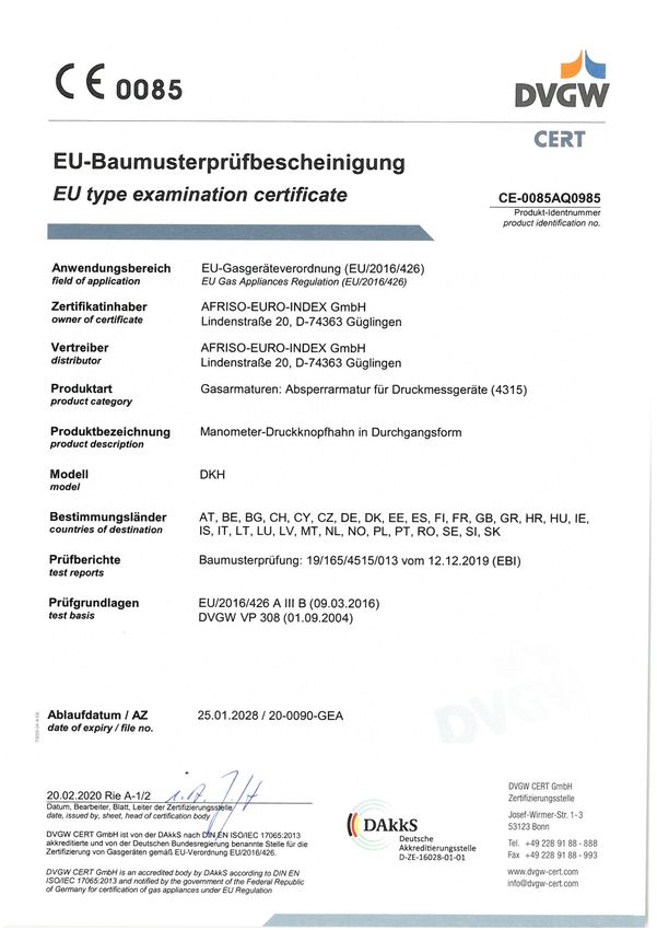
13.1 EU-Baumusterprüfbescheinigung
Manometer-Druckknopfhahn 14Anhang DE
Manometer-Druckknopfhahn 15Anhang DE
13.2 DVGW-Baumusterprüfzertifikat
Manometer-Druckknopfhahn 16Anhang DE
Manometer-Druckknopfhahn 17Anhang DE
13.3 EU-Konformitätserklärung
Manometer-Druckknopfhahn 18Operating
instructions
Pressure gauge push-button stop cock
Copyright 2020 AFRISO-EURO-INDEX GmbH.All rights reserved.
Lindenstraße 20
74363 Güglingen
Telefon+49 7135 102-0
Service+49 7135-102-211
Telefax +49 7135-102-147
info@afriso.com
Version: 03.2020.0
www.afriso.com
ID: 900.000.0220About these operating instructions EN
1 About these operating instructions
These operating instructions describe the pressure gauge push-button stop
cock (also referred to as "product" in these operating instructions). These
operating instructions are part of the product.
• You may only use the product if you have fully read and understood these
operating instructions.
• Verify that these operating instructions are always accessible for any type
of work performed on or with the product.
• Pass these operating instructions as well as all other product-related doc-
uments on to all owners of the product.
• If you feel that these operating instructions contain errors, inconsisten-
cies, ambiguities or other issues, contact the manufacturer prior to using
the product.
There operating instructions are protected by copyright and may only be
used as provided for by the corresponding copyright legislation. We reserve
the right to modifications.
The manufacturer shall not be liable in any form whatsoever for direct or con-
sequential damage resulting from failure to observe these operating instruc-
tions or from failure to comply with directives, regulations and standards and
any other statutory requirements applicable at the installation site of the prod-
uct.
Pressure gauge push-button stop cock 2Information on safety EN
2 Information on safety
2.1 Safety messages and hazard categories
These operating instructions contain safety messages to alert you to poten-
tial hazards and risks. In addition to the instructions provided in these oper-
ating instructions, you must comply with all directives, standards and safety
regulations applicable at the installation site of the product. Verify that you are
familiar with all directives, standards and safety regulations and ensure com-
pliance with them prior to using the product.
Safety messages in these operating instructions are highlighted with warning
symbols and warning words. Depending on the severity of a hazard, the
safety messages are classified according to different hazard categories.
WARNING
WARNING indicates a potentially hazardous situation, which, if not avoided,
can result in serious injury or equipment damage.
NOTICE
NOTICE indicates a hazardous situation, which, if not avoided, can
result in equipment damage.
In addition, the following symbols are used in these operating instructions:
This is the general safety alert symbol. It alerts to injury haz-
ards or equipment damage. Comply with all safety instruc-
tions in conjunction with this symbol to help avoid possible
death, injury or equipment damage.
Pressure gauge push-button stop cock 3Information on safety EN
2.2 Intended use
This product may only be used as shut-off unit between measuring line and
pressure gauge; it is suitable for gases (as per DVGW G260 and SVGW).
Any use other than the application explicitly permitted in these operating
instructions is not permitted and causes hazards.
Verify that the product is suitable for the application planned by you prior to
using the product. In doing so, take into account at least the following:
• All directives, standards and safety regulations applicable at the installa-
tion site of the product
• All conditions and data specified for the product
• The conditions of the planned application
In addition, perform a risk assessment in view of the planned application,
according to an approved risk assessment method, and implement the
appropriate safety measures, based on the results of the risk assessment.
Take into account the consequences of installing or integrating the product
into a system or a plant.
When using the product, perform all work and all other activities in conjunc-
tion with the product in compliance with the conditions specified in the oper-
ating instructions and on the nameplate, as well as with all directives, stand-
ards and safety regulations applicable at the installation site of the product.
2.3 Predictable incorrect application
The product must never be used in the following cases and for the following
purposes:
• Liquids
• Other gases
• In rooms which are not sufficiently vented
Pressure gauge push-button stop cock 4Information on safety EN
2.4 Qualification of personnel
Only appropriately trained persons who are familiar with and understand the
contents of these operating instructions and all other pertinent product docu-
mentation are authorized to work on and with this product.
These persons must have sufficient technical training, knowledge and expe-
rience and be able to foresee and detect potential hazards that may be
caused by using the product.
All persons working on and with the product must be fully familiar with all
directives, standards and safety regulations that must be observed for per-
forming such work.
2.5 Personal protective equipment
Always wear the required personal protective equipment. When performing
work on and with the product, take into account that hazards may be present
at the installation site which do not directly result from the product itself.
2.6 Modifications to the product
Only perform work on and with the product which is explicitly described in
these operating instructions. Do not make any modifications to the product
which are not described in these operating instructions.
Pressure gauge push-button stop cock 5Transport and storage EN
3 Transport and storage
The product may be damaged as a result of improper transport or storage.
NOTICE
INCORRECT HANDLING
• Verify compliance with the specified ambient conditions during transport or
storage of the product.
• Use the original packaging when transporting the product.
• Store the product in a clean and dry environment.
• Verify that the product is protected against shocks and impact during trans-
port and storage.
Failure to follow these instructions can result in equipment damage.
Pressure gauge push-button stop cock 6Product description EN
4 Product description
4.1 Product marking
The engraving is used to identify the product.
A. Product ID as per Regulation on
Appliances Burning Gaseous
Fuels EU/2016/426
A
Pressure gauge push-button stop cock 7Product description EN
4.2 Overview
A A. Pressure gauges
B. Push-button stop cock
C. Indicate pressure
D. Release pressure
E. Supply
B
C
D
E
Pressure gauge push-button stop cock 8Product description EN
4.3 Dimensions
64 mm
A. Rp½; G½
A B. Rp½; G½
71.5 (Rp½) / 73.5 (G½)
B
Fig. 1: Dimensions and connections (Rp ½; G ½)
64 mm A. Rp¼; G¼
A B. Rp¼; G¼
53.5 mm
B
Fig. 2: Dimensions and connections (Rp¼; G¼)
Pressure gauge push-button stop cock 9Product description EN
4.4 Function
Normally, the product is closed. In this state, there is no pressure applied to
the pressure gauge. When the pushbutton of the product is pressed, the
pressure gauge is filled with gas and the operating pressure is indicated.
4.5 Approvals, conformities, certifications
The product complies with:
• DVGW and SVGW
• EC Type Examination Certificate
4.6 Technical specifications
Parameter Value
General specifications
Housing material Brass, nickel-plated
Operating overpressure for gas as Max. 5 bar
medium
Direction of flow Designated by arrow
Tightness class 1
Connection 2 x female thread
Rp½ (EN 10226)
Rp¼ (EN 10226)
G½ (DIN ISO 228-1)
G¼ (DIN ISO 228-1)
Operating temperature range
Ambient temperature operation -20/+60 °C
Ambient temperature medium 0/+70 °C
Pressure gauge push-button stop cock 10Mounting EN
5 Mounting
5.1 Mounting the product
WARNING
MEDIUM ESCAPING UNDER PRESSURE
• Verify that there is no pressure in the system.
Failure to follow these instructions can result in death, serious injury or
equipment damage.
WARNING
ESCAPING GASES
• Verify that the product is only installed in dry, well-vented rooms.
Failure to follow these instructions can result in death, serious injury or
equipment damage.
Any mounting position is permissible.
1. Screw the product onto a T piece of the gas line so that it is tight.
- Verify correct direction of flow (indicated by an arrow on the product)
2. Firmly screw in the pressure gauge.
- Seal materials: DIN 3535 T3, T4; DIN 30660/30661; CU profile seal
Pressure gauge push-button stop cock 11Operation EN
6 Operation
1. Press the pushbutton piston all
the way to the stop.
- The system pressure is now
applied to the pressure gauge
and the pressure can be read at
the pressure gauge.
2. Release the pushbutton.
- Actuated by a spring, the push-
button returns to its original posi-
tion and the system pressure is
shut-off from the pressure
gauge.
- The gas in the pressure gauge is
relieved into the environment.
Fig. 3: Switching scheme
Pressure gauge push-button stop cock 12Maintenance EN
7 Maintenance
The product is maintenance-free.
8 Troubleshooting
Malfunctions may only be repaired by the manufacturer.
9 Decommissioning, disposal
Dispose of the product in compliance with all applicable directives, standards
and safety regulations.
1. Dismount the product (see chapter "Mounting", reverse sequence of
steps).
2. Dispose of the product.
10 Returning the device
Get in touch with us before returning your product service@afriso.de).
11 Warranty
See our terms and conditions at www.afriso.com or your purchase contract
for information on warranty.
12 Spare parts and accessories
Product
Product designation Part no. Figure
Pressure gauge push-button stop cock 63031 -
"Rp½"
Pressure gauge push-button stop cock 63191 -
"Rp¼"
Pressure gauge push-button stop cock 63087 -
"G½"
Pressure gauge push-button stop cock 13Appendix EN
13 Appendix
13.1 EU Type Examination Certificate
Pressure gauge push-button stop cock 14Appendix EN Pressure gauge push-button stop cock 15
Appendix                                    EN

13.2 DVGW Type Examination Certificate

                              Pressure gauge push-button stop cock   16
Appendix EN Pressure gauge push-button stop cock 17
Appendix                                    EN

13.3 EU Declaration of Conformity

                              Pressure gauge push-button stop cock   18
Notice technique
Robinet d'arrêt à bouton pour manomètre
Copyright 2020 AFRISO-EURO-INDEX GmbH. Tous droits réservés.
Lindenstraße 20
74363 Güglingen
Téléphone +49 7135 102-0
Service +49 7135 102-211
Telefax +49 7135 102-147
info@afriso.com
Version: 03.2020.0
www.afriso.com
ID: 900.000.0220La présente notice technique FR
1 La présente notice technique
Cette notice technique contient la description du robinet d'arrêt à bouton pour
manomètre (dénommé ci-après "produit"). Cette notice technique fait partie
du produit.
• Utilisez le produit seulement après que vous aurez lu et compris intégra-
lement la notice technique.
• Assurez-vous que la notice technique est disponible en permanence pour
toutes les opérations relatives au produit.
• Transmettez la notice technique et toute la documentation relative au pro-
duit à tous les utilisateurs du produit.
• Si vous êtes d'avis que la notice technique contient des erreurs, des
contradictions ou des ambiguïtés, adressez-vous au fabricant avant d'uti-
liser le produit.
Cette notice technique est protégée au titre de la propriété intellectuelle ; elle
doit être utilisée exclusivement dans le cadre autorisé par la loi. Sous réserve
de modifications.
La responsabilité du fabricant ou la garantie ne pourra être engagée pour des
dommages ou dommages consécutifs résultant d'une inobservation de cette
notice technique ou des directives, règlements et normes en vigueur sur le
lieu d'installation du produit.
Robinet d'arrêt à bouton pour manomètre 2Informations sur la sécurité FR
2 Informations sur la sécurité
2.1 Consignes de sécurité et classes de risques
Cette notice technique contient des consignes de sécurité destinées à attirer
l'attention sur les dangers et les risques. Outre les instructions contenues
dans cette notice technique, il faut vous assurer de l'observation de tous les
règlements, normes et consignes de sécurité en vigueur sur le lieu d'installa-
tion du produit. Avant d'utiliser le produit assurez-vous que tous les règle-
ments, normes et consignes de sécurité sont connus et respectés.
Dans cette notice technique les consignes de sécurité sont identifiables à
l'aide de symboles de mise en garde et de mots d'avertissement. En fonction
de la gravité du risque les consignes de sécurité sont réparties dans diffé-
rentes classes de risques.
AVERTISSEMENT
AVERTISSEMENT signale une situation potentiellement dangereuse qui, si
elle n'est pas évitée, peut entraîner la mort ou des blessures graves ou un
dommage matériel.
AVIS
AVIS signale une situation potentiellement dangereuse qui, si elle n'est pas
évitée, peut entraîner un dommage matériel.
Les symboles suivants sont également utilisés dans cette notice technique :
Ceci est le pictogramme général de mise en garde. Il signale
un risque de blessure et de dommage matériel. Respectez
toutes les consignes de sécurité afin d'éviter des accidents
mortels, des blessures ou des dommages matériels.
Robinet d'arrêt à bouton pour manomètre 3Informations sur la sécurité FR
2.2 Usage normal
Ce produit est destiné exclusivement á l'utilisation comme unité d'arrêt entre
la ligne de mesure et un manomètre; il est adapté pour les gaz (selon DVGW
G260 et SVGW).
Toute autre utilisation n'est pas conforme et cause des risques.
Avant d'utiliser le produit, assurez-vous que le produit est adapté à l'usage
que vous prévoyez. À cet effet, tenez compte au moins de ce qui suit :
• Tous les règlements, normes et consignes de sécurité sur le lieu d'instal-
lation
• Toutes les conditions et données spécifiées pour le produit
• Toutes les conditions d'application que vous prévoyez
En outre effectuez une évaluation des risques portant sur l'application
concrète que vous prévoyez à l'aide d'un procédé reconnu et prenez toutes
les mesures de sécurité nécessaires correspondant au résultat. Prenez
aussi en compte les conséquences possibles du montage ou de l'intégration
du produit dans un système ou une installation.
Pendant l'utilisation du produit effectuez toutes les opérations exclusivement
dans les conditions spécifiées dans cette notice technique et sur la plaque
signalétique, conformément aux données techniques spécifiées et en accord
avec tous les règlements, normes et consignes de sécurité en vigueur sur le
lieu d'installation.
2.3 Utilisation non conforme prévisible
Le produit ne doit, en particulier, pas être utilisé dans les cas suivants :
• Liquides
• Autres gaz
• Dans les pièces sans ventilation suffisante
Robinet d'arrêt à bouton pour manomètre 4Informations sur la sécurité FR
2.4 Qualification du personnel
Seul le personnel dûment qualifié est autorisé à travailler sur le produit et
avec celui-ci après qu'il aura connu et compris le contenu de cette notice
technique, ainsi que toute la documentation faisant partie du produit.
S'appuyant sur sa formation spécialisée, ses connaissances et ses expé-
riences, le personnel qualifié doit être en mesure de prévoir et reconnaître les
dangers qui peuvent être causés par l'utilisation du produit.
Tous les règlements, normes et consignes de sécurité en vigueur sur le lieu
d'installation doivent être connus du personnel qualifié travaillant sur le pro-
duit et avec celui-ci.
2.5 Équipement de protection individuelle
Utilisez toujours l'équipement de protection individuel requis. En travaillant
sur le produit et avec celui-ci, tenez compte des dangers susceptibles de se
présenter sur le lieu d'installation lesquels n'émanent pas directement du
produit.
2.6 Modification du produit
En travaillant sur le produit et avec celui-ci, effectuez exclusivement les opé-
rations décrites dans cette notice technique. N'effectuez pas de modifica-
tions non décrites dans cette notice technique.
Robinet d'arrêt à bouton pour manomètre 5Transport et stockage FR
3 Transport et stockage
Un transport et un stockage inadéquats risquent de causer des dommages
au produit.
AVIS
MANUTENTION INAPPROPRIÉE
• Assurez-vous que les conditions ambiantes spécifiées sont respectées pen-
dant le transport et le stockage.
• Utilisez l'emballage d'origine pour le transport.
• Stockez le produit dans un lieu sec et propre.
• Assurez-vous que le produit est à l'abri des chocs pendant le transport et le
stockage.
La non-observation de ces instructions peut causer des dommages maté-
riels.
Robinet d'arrêt à bouton pour manomètre 6Description du produit FR
4 Description du produit
4.1 Marquage du produit
La gravure permet d'identifier le produit.
A. Marquage CE selon le règlement
concernant les appareils brûlant
des combustibles gazeux UE/
2016/426
A
Robinet d'arrêt à bouton pour manomètre 7Description du produit FR
4.2 Aperçu
A A. Manomètre
B. Robinet d'arrêt à bouton
C. Afficher la pression
D. Isoler la pression
E. Arrivée
B
C
D
E
Robinet d'arrêt à bouton pour manomètre 8Description du produit FR
4.3 Dimensions
64 mm
A. Rp½; G½
A B. Rp½; G½
71,5 (Rp½) / 73,5 (G½)
B
Figure 1: Dimensions et raccordements (Rp ½; G ½)
64 mm A. Rp¼; G¼
A B. Rp¼; G¼
53,5 mm
B
Figure 2: Dimensions et raccordements (Rp¼; G¼)
Robinet d'arrêt à bouton pour manomètre 9Description du produit FR
4.4 Fonctionnement
Normalement, le produit est fermé. Dans cet état, il n'y a aucune pression
appliquée au manomètre. Lorsque le bouton du produit est pressé, le mano-
mètre est rempli de gaz et la pression de service s'affiche.
4.5 Agréments, certificats, déclarations
Le produit est conforme à :
• DVGW et SVGW
• Attestation d'examen UE de type
4.6 Caractéristiques techniques
Paramètre Valeur
Caractéristiques générales
Matériau du boîtier Laiton, nickelé
Pression de service pour gaz 5 bar max.
Sens de passage Indiqué par la flèche
Classe d'étanchéité 1
Raccordement 2 x filetage femelle
Rp½ (EN 10226)
Rp¼ (EN 10226)
G½ (DIN ISO 228-1)
G¼ (DIN ISO 228-1)
Conditions environnementales
Température ambiante de fonctionnement -20 ... 60 °C
Température ambiante pour le fluide 0 ... 70 °C
Robinet d'arrêt à bouton pour manomètre 10Montage FR
5 Montage
5.1 Montage du produit
AVERTISSEMENT
FLUIDE ÉCHAPPÉ SOUS PRESSION
• Vérifiez l'absence de pression dans le système.
La non-observation de ces instructions peut causer la mort ou des bles-
sures graves ou un dommage matériel.
AVERTISSEMENT
FUITE DE GAZ
• Assurez-vous que le produit est installé uniquement dans des pièces sèches
et bien ventilées.
La non-observation de ces instructions peut causer la mort ou des bles-
sures graves ou un dommage matériel.
La position de montage du produit est au choix.
1. Vissez le produit sur un raccord en T du tube de gaz.
- Au montage du produit, vérifiez le sens du passage correct (indiqué par
la flèche)
2. Vissez le manomètre.
- Matériaux d'étanchéification : DIN 3535 T3, T4; DIN 30660/30661; joint
profilé, cuivre
Robinet d'arrêt à bouton pour manomètre 11Service FR
6 Service
1. Appuyez sur le bouton-poussoir
jusqu'à l'arrêt.
- La pression du système est
maintenant appliquée au mano-
mètre et la pression peut être lue
sur le manomètre.
2. Relâchez le bouton-poussoir.
- Actionné par un ressort, le bou-
ton-poussoir revient à sa posi-
tion initiale et la pression du sys-
tème ne parvient plus au
manomètre.
- Le gaz dans le manomètre est
déchargé dans l'environnement.
Figure 3: Schéma
Robinet d'arrêt à bouton pour manomètre 12Maintenance FR
7 Maintenance
Le produit ne demande pas de maintenance.
8 Suppression des dérangements
Les dérangements doivent être éliminés uniquement par le fabricant.
9 Mise hors service et élimination
Pour éliminer le produit, conformez-vous aux règlements, normes et
consignes de sécurité en vigueur.
1. Démontez le produit (voir chapitre "Montage", effectuez les opérations en
ordre inverse).
2. Éliminez le produit.
10 Retour
Avant de retourner le produit, il faut que vous preniez contact avec nous (ser-
vice@afriso.de).
11 Garantie
Les informations sur la garantie figurent dans nos "Conditions générales de
vente" sur le site www.afriso.com ou dans votre contrat d'achat.
12 Pièces détachées et accessoires
Produit
Désignation de l'article Référence Figure
Robinet d'arrêt à bouton pour manomètre 63031 -
"Rp½"
Robinet d'arrêt à bouton pour manomètre 63191 -
"Rp¼"
Robinet d'arrêt à bouton pour manomètre 63087 -
"G½"
Robinet d'arrêt à bouton pour manomètre 13Annexe FR
13 Annexe
13.1 Attestation d'examen UE de type
Robinet d'arrêt à bouton pour manomètre 14Annexe FR Robinet d'arrêt à bouton pour manomètre 15
Annexe                                       FR

13.2 Attestation d'examen DVGW de type

                            Robinet d'arrêt à bouton pour manomètre   16
Annexe FR Robinet d'arrêt à bouton pour manomètre 17
Annexe                                       FR

13.3 Déclaration de conformité UE

                             Robinet d'arrêt à bouton pour manomètre   18
Sie können auch lesen