GSM-2/GSM-2-GPIO/GSM-2-GPS - Installations- und Bedienungsanleitung
←
→
Transkription von Seiteninhalten
Wenn Ihr Browser die Seite nicht korrekt rendert, bitte, lesen Sie den Inhalt der Seite unten
udomi GmbH                Hochfeldstraße 8                  D-74632 Neuenstein      Germany
Phone: +49-7942-9420891   Fax: +49-7942-9420898             email: sales@udomi.de   www.udomi.de

        GSM-2/GSM-2-GPIO/GSM-2-GPS
     Installations- und Bedienungsanleitung

                                                  Rev 2.2

1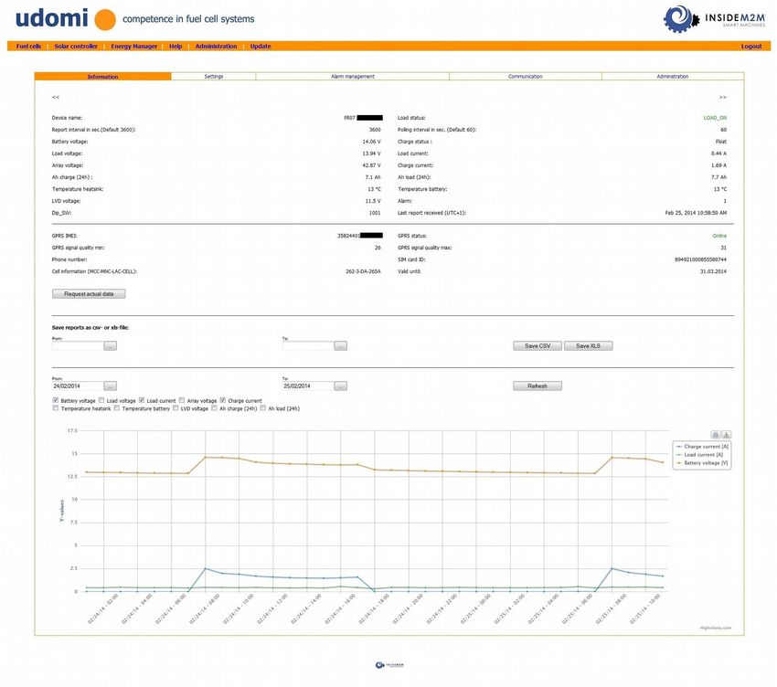
udomi GmbH Hochfeldstraße 8 D-74632 Neuenstein Germany
Phone: +49-7942-9420891 Fax: +49-7942-9420898 email: sales@udomi.de www.udomi.de
Installationsanleitung GSM-2 (GPRS Standard Modus)
Funktionsbeschreibung: Schritt 1: Einlegen der SIM Karte
Zur Überwachung der EFOY Brennstoffzelle
wurde die udomi off grid monitor Lösung
entwickelt. Damit ist es möglich, an jedem
Standort mit GSM Abdeckung eine einfach
zu bedienende und kostengünstige
Überwachung der EFOY Brennstoffzelle zu
realisieren. Das GSM-2 kommuniziert mit der
EFOY Brennstoffzelle und meldet Störungen
bzw. informiert rechtzeitig wenn der
Methanolkanister gewechselt werden muss.
Über das udomi-off-grid-monitor Portal kann Zum Betrieb benötigen Sie eine SIM-Karte (1,8 Volt
die EFOY Brennstoffzelle via Webbrowser oder 3 Volt, entsprechend der Richtlinie GSM 11.12)
einfach und komfortabel überwacht werden. mit GPRS Unterstützung. Bei den
Defaulteinstellungen für den Standard GPRS Modus
Lieferumfang: des GSM-2 Modems liegt das Datenvolumen bei ca.
GSM-2 Modem bzw. GSM-GPS-2 Modul 2MB/Monat. Zu empfehlen sind Datentarife mit 10KB
Stromversorgungskabel (einseitig RJ11, Taktung. Verwenden Sie das GSM-2 im SMS Modus
einseitig Kabelendhülsen mit +(rot) und werden keine Daten per GPRS übermittelt (siehe
–(schwarz) Markierung auch Installationsanleitung GSM-2-SMS).
Anschlußkabel seriell zum Verbinden des
GSM-2 mit der EFOY Brennstoffzelle WICHTIG: Vor Erstinbetriebnahme muss die
(„Data Interface“). Einseitig 9-polig Pinabfrage der SIM Karte deaktiviert sein oder die Pin
SUB-D, einseitig RJ45 muss „1538“ (Default Einstellung GSM-2) lauten.
2-fach Adapter RJ45
Hutschienenhalterung Die SIM-Karte muss in den Halter („Schublade") auf
Quadband GSM Antenne (Lieferumfang der Rückseite eingesetzt werden:
bei GSM-2 und GSM-2-GPIO) 1. Stellen Sie sicher, dass das Terminal ausgeschaltet
ist (Spannungsversorgung abgesteckt!)!
GSM/GPS Kombiantenne (Lieferumfang 2. Drücken Sie – z.B. mit einem Kugelschreiber – auf
bei GSM-GPS-2) den kleinen Knopf neben der Schublade des Halters.
Die Schublade wird hierdurch ein kleines Stück
herausgeschoben.
3. Ziehen Sie die Schublade heraus und setzen Sie
Ihre SIM-Karte ein. Achten Sie auf die richtige Lage:
Im Schubfach ist eine kleine abgeschrägte Ecke, so
Installationsanleitung für EFOY-PRO-
dass die SIM-Karte nur in einer definierten Position
Online (GSM-2/GSM-GPS-2)
eingesetzt werden kann.
4. Schieben Sie die Schublade vorsichtig zurück in
das Terminal. Die Schublade muss leicht
eingeschoben werden und darf nicht verkanten oder
verklemmen!
Die SIM-Karte darf nur bei ausgeschaltetem Terminal
eingesetzt und/oder gewechselt werden. Der Wechsel
bei anliegender Versorgungsspannung kann zu
irreversibler Beschädigung der SIM-Karte und des
Terminals führen. In den Schlitz der Schublade
dürfen keine Fremdkörper eingeführt werden! Wenn
Sie die SIM-Karte entnehmen, setzen Sie die leere
Schublade wieder ein, so dass keine Fremdkörper
eindringen können!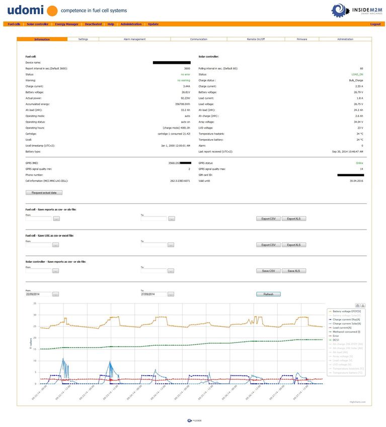
udomi GmbH Hochfeldstraße 8 D-74632 Neuenstein Germany
Phone: +49-7942-9420891 Fax: +49-7942-9420898 email: sales@udomi.de www.udomi.de
Installationsanleitung GSM-2 (GPRS Standard Modus)
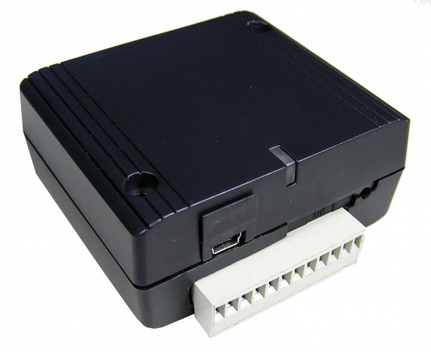
Schritt 2: Anschluß Antennenkabel (FME Schritt 4: Anschließen der Spannungsversorgung
Stecker)
Beachten Sie, dass der Antennenanschluss ein
FME-Stecker (50 Ω, male) ist. Schließen Sie hier
nur GSM-Antennen mit FME-Kabelbuchse (50 Ω, Schließen Sie das GSM-2 Modem unter
female) an. Das GSM-GPS-2 Modul verfügt Verwendung des mitgelieferten Strom-
zusätzlich über eine SMA Buchse für GPS. versorgungskabels polrichtig (+ und – Markierung
beachten Pin1 = VCC (+), Pin6 = GND (-)) an
eine Gleichspannungsquelle (8-30VDC) an.
Schritt 3: Anschließen des seriellen Das GSM-2 ist jetzt betriebsbereit und wird sich
Anschlußkabels automatisch ins GSM-Netz einbuchen und danach
eine Verbindung zum udomi-off-grid-monitor
Portal aufbauen. Die Zugangsdaten für das
udomi-off-grid-monitor Portal finden Sie auf dem
GSM-2 Modem. Für die weiteren Einstellungen
loggen Sie sich bitte unter
https://www.m2mgate.de/udomi/ ins udomi-off-
grid-monitor Portal ein.
Für Fragen stehen wir Ihnen unter +49-7942-
9420891 oder info@udomi.de zur Verfügung.
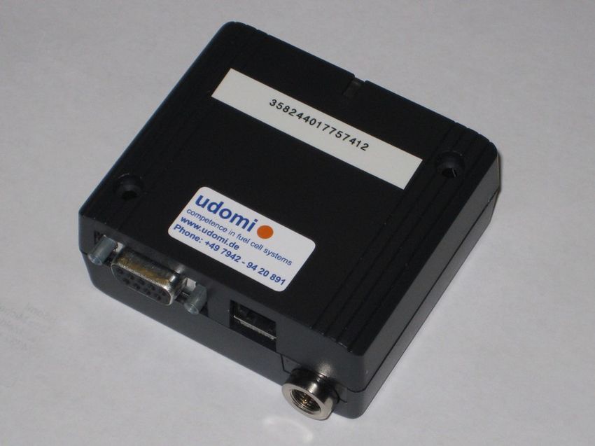
LED Anzeige GSM-2
Verbinden Sie die serielle Schnittstelle des GSM-2
Modems (siehe Abbildung) mit dem „Data
Interface“ der EFOY Pro Brennstoffzelle.
Verwenden Sie dazu das mitgelieferte serielle
Anschlußkabel (Einseitig 9-polig SUB-D, einseitig
RJ45).
Tip: Der optional erhältliche Tankpatronensensor
FS1 ist ebenfalls am „Data Interface“ der EFOY
Pro Brennstoffzelle anzuschließen.. Um sowohl
GSM-2 als auch FS1 an das „Data Interface“
Zur Kontrolle des GSM- und Betriebs-Status
anzuschließen verwenden Sie bitte den
befindet sich an der Rück- bzw. Oberseite des
mitgelieferten 2-fach Adapter.
Terminals eine zweifarbige LED-Anzeige.
3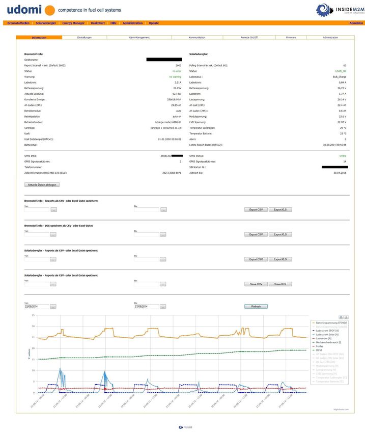
udomi GmbH                Hochfeldstraße 8        D-74632 Neuenstein      Germany
Phone: +49-7942-9420891   Fax: +49-7942-9420898   email: sales@udomi.de   www.udomi.de

Installationsanleitung GSM-2 (GPRS Standard Modus)
udomi GmbH                Hochfeldstraße 8          D-74632 Neuenstein                Germany
Phone: +49-7942-9420891   Fax: +49-7942-9420898     email: sales@udomi.de             www.udomi.de

Installationsanleitung GSM-2 (GPRS Standard Modus)

Spannungsversorgung Anschlußbelegung
Pin              Bezeichnung       Beschreibung                         Parameter
1                VCC               Positive Versorgungsspannung         +8 bis + 30VDC
2                Nicht verwendet
3                Nicht verwendet
4                Nicht verwendet
5                Nicht verwendet
6                GND               Masse                                0V

RS-232 Schnittstelle Anschlußbelegung
Pin                 Bezeichnung       I/O                               Beschreibung
1                   Nicht benutzt
2                   RXD               O                                 Reveice Data
3                   TXD               I                                 Transmit Data
4                   Nicht benutzt
5                   GND                                                 Signalmasse
6                   Nicht benutzt
7                   Nicht benutzt
8                   Nicht benutzt
9                   Nicht benutzt

Leistungsaufnahme

5
udomi GmbH Hochfeldstraße 8 D-74632 Neuenstein Germany Phone: +49-7942-9420891 Fax: +49-7942-9420898 email: sales@udomi.de www.udomi.de Bedienungsanleitung GSM-2 (GPRS Standard Modus) Login Unter https://www.m2mgate.de/udomi können Sie sich in den udomi-off-grid-monitor Portal einloggen. Registrierte Benutzer geben Ihren User Namen und das Passwort ein. Zur erstmaligen Registrierung klicken Sie bitte auf „Create Account...“ Schriftzug. Hier können Sie Ihren Login erstellen. Einem bestehenden Login weitere GSM-2 Modems zuweisen Haben Sie bereits einen Login dann können Sie weitere GSM-2 Modems im Menuepunkt Administration hinzufügen. Dazu die komplette IMEI Nummer des neuen Modems eingeben.
udomi GmbH Hochfeldstraße 8 D-74632 Neuenstein Germany Phone: +49-7942-9420891 Fax: +49-7942-9420898 email: sales@udomi.de www.udomi.de Bedienungsanleitung GSM-2 (GPRS Standard Modus) Status-Information Nach dem Anmelden werden unter dem Reiter Brennstoffzellen alle angemeldeten GSM-2 Modems angezeigt. Neben dem Menuepunkt Brennstoffzellen können die Menuepunkte Solarladeregler, Hilfe und Administration ausgewählt werden. Nach anklicken eines der Geräte, erscheint die Brennstoffzellen-Detailansicht mit den folgenden vier Menuepunkten: - Information - Einstellungen - Alarmmanagement - Kommunikation In der Solarladeregler Detailansicht sind folgende Menuepunkte verfügbar: - Information - Einstellungen - Alarmmanagement - Kommunikation 7
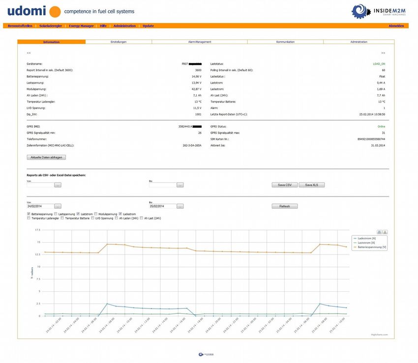
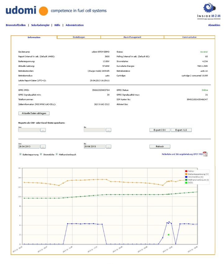
udomi GmbH Hochfeldstraße 8 D-74632 Neuenstein Germany Phone: +49-7942-9420891 Fax: +49-7942-9420898 email: sales@udomi.de www.udomi.de Bedienungsanleitung GSM-2 (GPRS Standard Modus) Information Auf der Information Seite sind die aktuellen Daten zur Brennstoffzelle bzw. Solarladeregler zusammengefasst. Alle Daten werden automatisch auf dem udomi off grid Server abgespeichert und können als Reportdatei in Excel oder csv Format abgerufen werden. Zusätzlich werden die wichtigsten Reportdaten auch grafisch dargestellt.
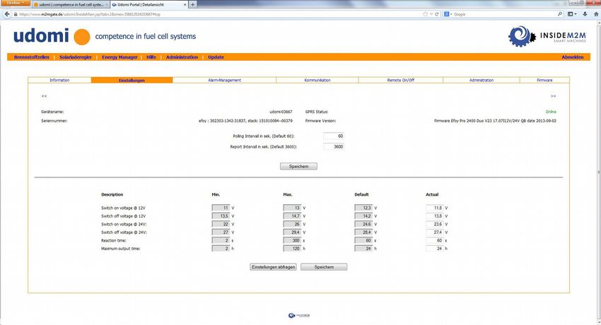
udomi GmbH Hochfeldstraße 8 D-74632 Neuenstein Germany Phone: +49-7942-9420891 Fax: +49-7942-9420898 email: sales@udomi.de www.udomi.de Bedienungsanleitung GSM-2 (GPRS Standard Modus) Einstellungen Unter dem Reiter Einstellungen in der Brennstoffzellen-Detailansicht, können diverse Werte konfiguriert werden. Das GSM-2 muss für das Ändern dieser Werte online sein. Report-Intervall Hier wird definiert, in welchen Zeitabständen ein Report mit den aktuellen Werten der Brennstoffzelle generiert und an das udomi-off-grid-monitor Portal übertragen wird. Die Defaulteinstellung beträgt 1 Stunde. Bei der Defaulteinstellung ergibt sich ein Datenvolumen von ca. 2Mbyte/Monat. Bei Übertragung der Reportdaten in kürzeren Abständen erhöht sich auch das monatlich abgerechnete Datenvolumen Ihres SIM Karten Providers geringfügig. Pollingintervall Hier wird definiert, in welchen Zeitabständen das GSM-2 Modem die Brennstoffzelle abfragt. Die Voreinstellung liegt bei 60 Sekunden. Bei jeder Abfrage überprüft das GSM-2 Modem ob ein Fehler bei der EFOY Pro Brennstoffzelle aufgetreten ist und sendet im Fehlerfall eine Alarmierung an das udomi-off-grid-monitor Portal sowie alle Empfänger (SMS/Email), die im Reiter „Alarm Management“ eingetragen sind. 9
udomi GmbH Hochfeldstraße 8 D-74632 Neuenstein Germany Phone: +49-7942-9420891 Fax: +49-7942-9420898 email: sales@udomi.de www.udomi.de Bedienungsanleitung GSM-2 (GPRS Standard Modus) Alarm Management Unter dem Reiter Alarmmanagement in der Brennstoffzellen-Detailansicht, können die Empfänger für die verschiedenen Alarmbedingungen definiert werden: - Cartridge Low (Alarmmeldung wenn FS1 Tankpatronensensor niedrigen Tankinhalt detektiert oder bei Umschalten des DCS1 Duocartswitch) - Error (Fehler Brennstoffzelle) - Unterschreitung der Batteriespannung Die Alarmierung kann per SMS oder E-Mail versendet werden. Die SMS werden vom Modem verschickt und über die Mobilfunkkarte des Modems abgerechnet. Die Email Alarmierung wird über das udomi-off-grid-monitor Portal versendet und ist in der Jahrespauschale für das udomi- off-grid-monitor Portal enthalten. SMS Alarme können nur konfiguriert werden wenn das GSM-2 Modem online ist.
udomi GmbH Hochfeldstraße 8 D-74632 Neuenstein Germany Phone: +49-7942-9420891 Fax: +49-7942-9420898 email: sales@udomi.de www.udomi.de Bedienungsanleitung GSM-2 (GPRS Standard Modus) Kommunikation Unter dem Reiter Kommunikation in der Brennstoffzellen-Detailansicht können Sie direkt mit der EFOY Pro Brennstoffzelle kommunizieren. Bei Eingabe des Kommando’s „?“ erhalten Sie eine Übersicht der Kommandos. Weitere Details zu den Kommandos finden Sie im Hilfe Menue. Mithilfe dieser Kommandos ist es möglich eventuell auftretende Fehler der EFOY Pro Brennstoffzelle via RESET Kommando zu beheben und die Konfiguration der EFOY Pro Brennstoffzelle für die jeweilige Applikation zu ändern. 11
udomi GmbH Hochfeldstraße 8 D-74632 Neuenstein Germany Phone: +49-7942-9420891 Fax: +49-7942-9420898 email: sales@udomi.de www.udomi.de Bedienungsanleitung GSM-2 (GPRS Standard Modus) Administration Im Menue Administration werden die Daten des Benutzerkontos verwaltet. - Konto (Benutzerdaten und Zuweisung von weiteren Modems zu einem bestehenden Benutzer/Login - Passwort ändern - Gerät benennen - Geräte SIM-Pin Mit der Auswahl PIN aktivieren wird die PIN Abfrage aktiviert (ansonsten wird die PIN nicht abgefragt). Beim Ersten Einbuchen des GSM-2 Modems muss die PIN Abfrage der SIM Karte deaktiviert sein oder die PIN auf die Default PIN des GSM-2 Modems geändert werden (Default PIN 1538). ACHTUNG: Nach dem Neustart des Gerätes wird die neu eingegebene PIN abgefragt. Sollte die SIM-Karte einen anderen PIN besitzen, wird die SIM-Karte gesperrt und kann nur wieder mit der Superpin (wird vom Provider zusammen mit den Daten Ihrer SIM-Karte geliefert) wieder frei geschaltet werden. Um Übertragungsprobleme bei der Übermittlung der PIN Nummer zu vermeiden sollte diese Funktion nur bei guter Funkverbindung (GPRS Signalqualität mind. 10; siehe Reiter Information) durchgeführt werden.
udomi GmbH                 Hochfeldstraße 8               D-74632 Neuenstein        Germany
Phone: +49-7942-9420891    Fax: +49-7942-9420898          email: sales@udomi.de     www.udomi.de

Bedienungsanleitung GSM-2 mit SS-MPPT-15L (Solarladeregler)

GSM-2 und GSM-GPS-2 Unterstützung für Solarladeregler SS-MPPT-15L

GSM-2 und GSM-GPS-2 bieten auch die Möglichkeit zur Remoteüberwachung des Morningstar
Solarladereglers SS-MPPT-15L. Damit können autarke Energieversorgungen bestehend aus
Solarmodul mit Akkupufferung, effizient überwacht werden.

Notwendiges Zubehör:
Meterbusadapter mit Verbindungskabel zum GSM-2/GSM-GPS-2

Schritt 1:
 Funktionsbeschreibung                             DIP Schalter Position
DIP Schalter Position 4 auf ON stellen für
Kommunikation über den Meterbusadapter

Den DIP Schalter Nr. 4 am SS-MPPT-15L auf Position „ON“ stellen.

Schritt 2:

GSM-2/GSM-GPS-2 über den Meterbusadapter (MSC Adapter) mit dem SS-MPPT-15L verbinden.
Schritt 3: GSM-2/GSM-GPS-2 mit SIM Karte bestücken
Schritt 4: GSM-2/GSM-GPS-2 und SS-MPPT-15L an Spannungsversorgung anschließen.
Schritt 5: Im udomi-off-grid-monitor-portal unter Eingabe Ihrer Login Daten einloggen.
www.m2mgate.de/udomi/
User: xxxx
Pass: xxxx

Schritt 6: Menuepunkt „Solarladeregler“ auswählen. Hier erscheint Ihr SS-MPPT-15L. Das GSM-2
Modem erkennt automatisch ob ein SS-MPPT-15L angeschlossen ist. Hat das GSM-2 Modem den SS-
MPPT-15L erkannt ist das Modem unter dem Menuepunkt „Solarladeregler“ zu finden. Es kann einige
Minuten dauern bis das GSM-2 Modem erkannt hat. Durch anklicken des Gerätenamens gelangen Sie
in die Untermenues „Informationen“, „Einstellungen“, Alarmmanagement“ und „Kommunikation“. Im
Menue „Kommunikation“ können folgende Befehle ausgeführt werden:
LOAD CONNECT: Lastausgang wird abgeschaltet
LOAD DISCONNECT: Lastausgang wird abgeschaltet
CHARGE CONNECT: Solareingang wird einganschaltet (Solarmodule laden den Akku)
CHARGE DISCONNECT: Solareingang wird abgeschaltet (Solarmodule laden den Akku nicht mehr).
RESET: Rücksetzen der SS-MPPT-15L Software

13
udomi GmbH                 Hochfeldstraße 8             D-74632 Neuenstein            Germany
Phone: +49-7942-9420891    Fax: +49-7942-9420898        email: sales@udomi.de         www.udomi.de

Bedienungsanleitung GSM-2 mit Solarladeregler SS-MPPT-15L

 • Information (Solarladeregler)
Im Menue „Information“ werden die aktuellen Daten vom Solarladeregler SS-MPPT-15L angezeigt. In
der Standardgrafikansicht werden die wichtigsten Daten (Batteriespannung, Last- und Ladestrom) der
letzten 2 Tage angezeigt. Weitere Daten wie Modulspannung, Ladereglertemperatur können anklicken
mit in der Grafik angezeigt werden. Auch die Zeitachse der Grafik kann geändert werden.

• Kommunikation
Im Menue „Kommunikation“ haben Sie die Möglichkeit den Lastausgang und Solareingang per
Knopfdruck ein und auszuschalten oder den Laderegler zu resetten.
udomi GmbH                  Hochfeldstraße 8               D-74632 Neuenstein       Germany
Phone: +49-7942-9420891     Fax: +49-7942-9420898          email: sales@udomi.de    www.udomi.de

Bedienungsanleitung GSM-2 mit MUX-2

MUX-2 zum Anschluß von EFOY-PRO Brennstoffzelle und SS-MPPT Solarladeregler an
das GSM-2 Modem

Mit dem MUX-2 können die EFOY PRO Brennstoffzelle und der Solarladeregler SS-MPPT-15L
gemeinsam an das GSM-2 angeschlossen werden. Auf dem udomi off grid monitor werden die Daten
von Brennstoffzelle und Solarladeregler zusammen erfasst und im Menuepunkt „Energy Manager“
angezeigt. Der Nutzer hat damit alle Informationen zu Brennstoffzelle, Batterie, Solarstrom und
Verbraucher im Blick.

Schritt 1:
 Funktionsbeschreibung                              DIP Schalter Position
DIP Schalter Position 4 auf ON stellen für
Kommunikation mit dem MUX-2

Schritt 2:
GSM-2 über den MUX-2 mit EFOY PRO (Data Interface) und SS-MPPT-15L verbinden.
Nach dem Einschalten erkennt das GSM-2 Modem automatisch ob der MUX-2 angeschlossen ist und
überträgt die Daten an das udomi offgrid monitor Portal.

15
udomi GmbH                  Hochfeldstraße 8              D-74632 Neuenstein            Germany
Phone: +49-7942-9420891     Fax: +49-7942-9420898         email: sales@udomi.de         www.udomi.de

Bedienungsanleitung GSM-2 mit MUX-2

• Information (Energymanager)
Bei Einsatz des MUX-2 können sowohl EFOY PRO und SS-MPPT-15L über das GSM-2 überwacht
werden. Im Menue „Information“ sind links die Daten der EFOY PRO und rechts die Daten des
Solarladereglers aufgelistet. Weiter unten werden die Daten für die EFOY PRO Brennstoffzelle und
Solarladeregler auch grafisch dargestellt. Durch Anklicken der Parameter in der Legende können
weitere Werte in der Grafik angezeigt werden.
udomi GmbH                  Hochfeldstraße 8           D-74632 Neuenstein                   Germany
Phone: +49-7942-9420891     Fax: +49-7942-9420898      email: sales@udomi.de                www.udomi.de

Bedienungsanleitung GSM-2-GPIO

GSM-2-GPIO

Mit dem GSM-2-GPIO werden die
Störungsmeldungen der EFOY Pro Brennstoffzelle
auch über 2 Relaisausgänge zur Verfügung gestellt.
Damit ist es einfach möglich die Störungen der EFOY
Pro in bestehende Meldetechnik zu integrieren.

Inputs (Alarm):
An die Inputs darf eine Spannung von max. 30VDC
angelegt werden. Sobald die Spannung am Input
von 0V auf eine Spannung > 5 Volt steigt wird ein
Alarm ausgelöst (Als Bezugspotential für alle
Alarminputs dient Pin 12 „Common Ground“). Die
Einstellung dieser Alarme kann im udomi-off-grid-
monitor Portal unter „GPIO“ festgelegt werden.                       GSM-2-GPIO

Output 1:                                             Pin   Funktion              Beschreibung
Ist der Relaisausgang 1 geschlossen (leitende         1          -                     NA
Verbindung zwischen Pin 8 und 9) dann liegt ein
Sammelfehler vor. Der Sammelfehler beinhaltet die     2      Input 1           Eingang 1 High aktiv
Fehler „ERROR Brennstoffzelle“ und „Alarmierung       3      Input 2           Eingang 2 High aktiv
bei niedriger Batteriespannung“. Der Relaisgang
bleibt solange geschlossen bis die Störung bzw. der   4      Input 3           Eingang 3 High aktiv
Spannungsalarm besteht.                               5      Input 4           Eingang 4 High aktiv

Output 2:                                             6      Input 5           Eingang 5 High aktiv
Bei angeschlossenem Tankpatronensensor FS1 wird       7      Input 6           Eingang 6 High aktiv
der Relaisausgang 2 geschlossen sobald der FS1
                                                      8     Output 1         Relaisausgang 1–
einen niedrigen Tankpatroneninhalt erkennt. Der
                                                                           Sammelfehler ERROR
Relaisausgang bleibt geschlossen bis der FS1 wieder
                                                                              EFOY Pro und
eine einen Füllstand oberhalb des Sensors             9     Output 1
                                                                          Unterspannung Batterie
detektiert.
Ist der Duocartswitch an die EFOY Pro                 10    Output 2         Relaisausgang 2–
angeschlossen dann wird der Relaisausgang                                        niedriger
geschlossen sobald der Duocartswitch von einer                             Tankpatronenfüllstand
                                                      11    Output 2
Tankpatrone auf die andere umschaltet. Der                                   und Umschaltung
Relaisausgang bleibt für 60 Sekunden geschlossen                              Duocartswitch
und öffnet dann wieder (Die 60 Sekunden
                                                      12         -              Common Ground
entsprechen dem Polling Intervall welches im udomi-
off-grid-monitor Portal unter dem Menuepunkt
„Einstellungen“ festgelegt wird. Wird dieser Wert
geändert ändert sich auch die Zeitintervall in dem
der Output 2 geschlossen wird.

Die Relaisausgänge werden auch dann geschaltet
wenn keine SIM Karte im GSM-2-GPIO eingelegt ist.
Die Relaisausgänge dürfen maximal mit 500mA bei
max. 30V belastet werden.

17
udomi GmbH Hochfeldstraße 8 D-74632 Neuenstein Germany Phone: +49-7942-9420891 Fax: +49-7942-9420898 email: sales@udomi.de www.udomi.de Bedienungsanleitung GSM-2-GPIO Im der Information Ansicht for GSM-2-GPIO Modems wird der Status der 6 digitalen Eingänge und der 2 Relaisausgänge angezeigt (siehe rot umrandeten Bereich). Mit dem Deaktivieren Knopf können die im Alarm Management konfigurierten I/O Alarme deaktiviert werden. Ein I/O Alarm wird ausgelöst sobald der Spannungspegel an dem digitalen Eingang von 0V auf über 2,5V steigt. Sind die I/O Alarme deaktiviert wird keine Alarmmeldung versendet. Mit dem Knopf Output manuell schalten kann der Anwender die digitalen Ausgangsrelais manuell über das udomi-off-grid-monitor Portal ein und ausschalten. Damit ist es möglich Lasten wie z.B. Lüfter und Heizungen aus der Ferne ein und auszuschalten (bei Lasten >500mA muss ein externes Relais zwischengeschaltet werden, siehe auch Seite 13). Ist der Knopf Output manuell schalten auf off dann werden die beiden Relaisausgänge des GSM-2-GPIO Modems benutzt um Störungen an der Brennstoffzelle oder Methanolmangel/Unterspannung zu signalisieren (siehe dazu Seite 13).
udomi GmbH                 Hochfeldstraße 8                D-74632 Neuenstein             Germany
Phone: +49-7942-9420891    Fax: +49-7942-9420898           email: sales@udomi.de          www.udomi.de

Bedienungsanleitung für GSM-2-SMS (SMS Modus)

Funktionsbeschreibung:                         Folgende Befehle (cmd) sind verfügbar:
Im Standardbetrieb arbeitet das GSM-           1. Alarmierung bei „ERROR“ der EFOY Pro
2/GSM-GPS-2 System im GPRS Modus und           Brennstoffzelle
steht dauernd in Verbindung mit dem            „addalarm“: Alarmmeldung via SMS wenn EFOY Pro
udomi-off-grid-monitor Portal über das eine    Brennstoffzelle auf Störung geht „ERROR”
komfortable Überwachung und                    „delalarm“: Löschen des Alarms
Konfiguration der EFOY Pro Brennstoffzelle     Beispiel:
möglich ist. Alternativ zum GPRS Betrieb       12345:addalarm:0170123333 - Tritt ein „ERROR“ bei
kann das GSM-2 Modem auch im SMS               der EFOY Pro Brennstoffzelle auf wird Alarmierung an
Betrieb benutzt werden. Beim SMS Betrieb       Mobilnummer 0170123333 gesendet
arbeitet das GSM-2 Modem autark und hat        12345:delalarm:0170123333 - Alarmierung bei
keine Verbindung mit dem udomi-off-grid-       „ERROR“ an Mobilnummer 01700123333 wird
monitor-Portal. Für den SMS Betrieb kann       gelöscht
jede Standard SIM Karte verwendet werden.
Kosten entstehen nur für die SMS die das       2. Alarmierung bei niedrigem Tankpatronenfüllstand
GSM-2 Modem versendet. Die Konfiguration       (Voraussetzung: Tankpatronensensor FS1 ist
des GSM-2 Modem wird über SMS                  angeschlossen)
Textnachrichten vorgenommen. Der               „addcart“: Alarmierung wenn Tankpatronensensor
Funktionsumfang im SMS Mode ist                FS1 niedrigen Füllstand meldet.
gegenüber dem komfortableren GPRS              „delcart”: Löschen des Füllstandalarms
Modus deutlich reduziert. Ein Upgrade des      Beispiel:
GSM-2 vom SMS auf GPRS Modus ist               12345:addcart:0170123333 - Sobald der
jederzeit durch Freischaltung von udomi        Tankpatronensensor niedrigen Füllstand meldet, wird
möglich.                                       eine Alarm SMS an Mobilnummer 0170123333
                                               gesendet
Das GSM-2-SMS System unterscheidet 3           12345:delcart:0170123333 -Alarmierung bei
verschiedene Alamierungen:                     niedrigem Füllstand Tankpatrone an Mobilnummer
    1. Alarmierung bei „ERROR“ der EFOY        01700123333 wird gelöscht
        Pro Brennstoffzelle
    2. Alarmierung bei niedrigem               3. Alarmierung bei niedriger Batteriespannung
        Tankpatroneninhalt (setzt den          Zunächst muss mit dem Befehl „setvolt“ der
        Einsatz des Tankpatronensensors        Spannungswert an das GSM-2 Modem übertragen
        FS1 voraus)                            werden, bei dessen Unterschreitung die Alarmierung
    3. Alarmierung bei niedriger               erfolgen soll.
        Batteriespannung (Schwellwert ist      „setvolt”: Wenn dieser Spannungswert unterschritten
        einstellbar)                           wird sendet das GSM-2-SMS eine Alarmmeldung via
                                               SMS. Bei Auslieferung ist der Wert für setvolt 0.0 Volt
Befehlsübersicht GSM-2-SMS                     (Default).
                                               „addvolt”: Alarmierung wenn die Batteriespannung
Im SMS Modus erfolgt die Konfiguration des     den mit „setvolt” programmierten Wert
GSM-2 Modems über SMS. Die SMS                 unterschreitet.
Kommandos setzen sich wie folgt                „delvolt”: Löschen des Unterspannungsalarms
zusammen.                                      Beispiel:
                                               12345:setvolt:11.8 – Unterschreitet die
xxxxx:cmd:value                                Batteriespannung 11.8 Volt (wichtig Dezimalpunkt)
xxxxx: die letzten 5 Ziffern der IMEI          erfolgt eine Alarmierung.
Nummer des GMS-2-SMS Modems (als               12345:addvolt:0170123333 – Fällt die
Passwort)                                      Batteriespannung unter den mit setvolt eingestellten
cmd: Befehl                                    Wert wird eine Alarm SMS an die Mobilnummer
value: Parameter für Befehl                    0170123333 gesendet.
                                               12345:delvolt:0170123333 - Alarmierung bei
                                               niedriger Batteriespannung an Mobilnummer
                                               01700123333 wird gelöscht.

19
udomi GmbH Hochfeldstraße 8 D-74632 Neuenstein Germany
Phone: +49-7942-9420891 Fax: +49-7942-9420898 email: sales@udomi.de www.udomi.de
Bedienungsanleitung für GSM-2-SMS (SMS Modus)
4. Masteralarm 9. Bestätigungs SMS
Mit dem „addall“ Befehl versendet das GSM-2-SMS Auf jedes SMS Kommando, das an das GSM-2-
eine SMS Alarmmeldung bei jedem der 3 SMS versendet wird, erhalten Sie eine
Alarmierungsfälle (ERROR, niedriger Bestätigungs SMS zurück. Auf SMS Befehl mit
Tankpatronenfüllstand und niedrige falschem Passwort reagiert das GSM-2-SMS
Batteriespannung) nicht.
„addall”: Alarmierung bei jedem der 3 Alarme
„delall”: Löschen des Masteralarms 10. Statusabfrage der EFOY Pro
Beispiel: Brennstoffzelle )
12345:addall:0170123333 -Im Alarmfall Beispiel:
Alarmierung an Mobilnummer 0170123333 12345:sfc:sfc – Mit diesem Befehl wird die
12345:delall:0170123333 -Alarmierung an Abfrage „SFC“ via SMS an die EFOY Pro
Mobilnummer 01700123333 wird gelöscht Brennstoffzelle gesendet. Das GSM-2-SMS
sendet den Status der Brennstoffzelle als SMS
5. Polling Intervall an das Mobiltelefon zurück.
Im Auslieferzustand fragt das GSM-2-SMS Modem Antwortbeispiel:
alle 60 Sekunden (Default) den Zustand der EFOY SFC>SFC
Pro Brennstoffzelle ab. Sobald ein Fehler (ERROR, battery voltage: 12.08V
niedriger Tankpatronenfüllstand oder niedrige output current: 0.0A
Batteriespannung) mindestens 2 mal operating time: 5.8h
hintereinander anliegt wird das GSM-2 Modem operating state: error
aktiv und versendet die Alarmierung via SMS. Bei operating mode: auto
Bedarf kann das Polling (Abfrageintervall) mit dem please change fuel cartridge
cartridge level below sensor
Befehl „setpoll” geändert werden:
SFC>
„setpoll“ Setzt das Polling Intervall in Sekunden
Beispiel:
11. Terminalverbindung mit EFOY Pro
12345:setpoll:120 (Abfrageintervall 120 Sekunden)
Brennstoffzelle
6. DEFAULT (Rücksetzen der GSM-2/GSM-GPS-2) Um die EFOY Pro Brennstoffzelle aus der
Konfiguration. Mit dem Senden des Befehls Ferne zu konfigurieren kann über das GSM-
„default“ werden alle Alarme gelöscht und das 2SMS auch eine direkte Verbindung mit der
GSM-2/GSM-GPS-2 Modem auf die Default seriellen Schnittstelle der EFOY Pro
Einstellungen zurückgesetzt. Brennstoffzelle hergestellt werden. Gehen Sie
Beispiel: dazu wie folgt vor:
12345:default: (GSM-2/GSM-GPS-2 wird auf Stellen Sie mittels Analogmodem und
Default Werte zurückgesetzt) Terminalsoftware (z.B. Hyperterminal) eine
Wählverbindung mit dem GSM-2-SMS Modem
7. GPS Abfrage (nur GSM/GPS-2) her. Einstellungen – 9600bit/s, 8bits/byte, 1
Mit dem Senden des Kommandos „gps“ sendet das Stop Bit, Keine Parität, keine Flussteuerung.
GSM-GPS-2 die aktuellen GPS Koordinaten via SMS. Beispiel:
Beispiel: ATD016045678
12345:gps: (GSM-GPS-2 sendet GPS Kordinaten via Nach erfolgreichem Verbindungsaufbau
SMS) (CONNECT…) geben Sie zur Authorisierung die
letzten 5 Ziffern der IMEI Nummer Ihres GSM-
8. RESET (Brennstoffzelle) 2 Modems ein. Ist die Authorisierung
Wenn an der EFOY Pro Brennstoffzelle ein Fehler erfolgreich erhalten Sie „OK“ als Antwort und
auftritt (z.B. „Please check exhaust tube“) können haben nun eine direkte Verbindung zur EFOY
Sie durch senden des „RESET“ Befehls einen Pro Brennstoffzelle (Details siehe dazu UM2
Neustart der EFOY Pro Brennstoffzelle auslösen. In Bedienungsanleitung der EFOY Pro
vielen Fällen läuft die EFOY Pro Brennstoffzelle Brennstoffzelle). Schlägt die Authorisierung
dann wieder an und liefert zuverlässig Energie. fehl erfolgt die Eingabe „bye“ und die
Beispiel: Verbindung wird vom GSM-2-SMS beendet.
12345:reset: - RESET der EFOY Pro Brennstoffzelleudomi GmbH Hochfeldstraße 8 D-74632 Neuenstein Germany
Phone: +49-7942-9420891 Fax: +49-7942-9420898 email: sales@udomi.de www.udomi.de
GSM-2/GSM-2-GPIO/GSM-GPS-2
Installation and Operation Manual
21udomi GmbH Hochfeldstraße 8 D-74632 Neuenstein Germany
Phone: +49-7942-9420891 Fax: +49-7942-9420898 email: sales@udomi.de www.udomi.de
Installation Manual GSM-2 (GPRS Standard Mode)
Function Step 1: Insert SIM Card
The udomi off grid monitor is perfectly
suited to monitor and control EFOY Pro fuel
cell systems in remote locations with GSM
coverage. Installation is easy. Just connect
the GSM-2 (GSM-GPS-2) module with the
Data Interface of the EFOY Pro unit, insert a
SIM card and the EFOY Pro unit will
automatically connect with the udomi-off-
grid-monitor-portal (machine to machine).
Using your standard web browser you can
monitor and control the EFOY Pro fuel cell.
In case of low fuel level or an error, the The SIM card has to support GPRS. A tariff with 10KB
system will automatically inform your service package size is the best choice. Data traffic is app
personnel via SMS and/or Email. In case of 2MB/month.
an error it is possible to communicate with
the EFOY Pro via the udomi-off-grid- Important: Before installing the SIM card please
monitor-portal. This increases reliability and deactivate the PIN or set the PIN to “1538“ (default
safes time and money. PIN of the GSM-2). You can change the PIN later via
the udomi-off-grid-monitor Portal.
List of components:
1. Make sure the GSM-2 is switched off - no power
GSM-2 Modem (GSM-GPS-2) supply connected!
Power supply cable (one side RJ11, one 2. Open the SIM lid using as shown in the picture
side open wires with +/- marking (+ --> above
red, - --> black) 3. Insert the SIM card in the correct orientation and
Serial interface cable to connect GSM-2 close the lid carefully
with EFOY Pro (“Data Interface“). One
end 9-pin SUB-D, one end RJ45 Step 2: Connect antenna (FME adapter). GSM-GPS-2
Y - Adapter RJ45 (to connect GSM-2 and module has additional SMA adapter for GPS.
Fuel Sensor FS1 with EFOY Pro “Data
Interface“
DIN Rail holder for GSM-Installation
manual for EFOY Pro-Online
Quad Band GSM antenna (included with
GSM-2 and GSM-2-GPIO)
GPS-GSM antenna (included with GSM-
GPS-2)
Installation Manualudomi GmbH Hochfeldstraße 8 D-74632 Neuenstein Germany
Phone: +49-7942-9420891 Fax: +49-7942-9420898 email: sales@udomi.de www.udomi.de
Installation Manual GSM-2 (GPRS Standard Mode)
Step 3: Connect serial cable LED Display GSM-2
Connect the serial interface of the GSM-2 with The GSM-2 has 2 LED’s (red and yellow) to
the “Data Interface” of the EFOY Pro device, indicate the system status.
using the serial interface cable
Yellow LED
Tip: If you want to use the FS1 (Fuel Sensor for Off Terminal in Sleep or Alarm Mode
the EFOY Pro Methanol cartridges) please use the 600ms on SIM card missing, PIN missing,
Y-adaptor RJ45 to connect both the GSM-2 and 600ms off searching for network
the FS-1 with the “Data Interface” of the EFOY 75ms on Connected with network, no data
Pro device. 3s off connection (IDLE Mode)
75ms on One or more GPRS connections
Step 4: Connect power supply 75ms off active (GPRS Mode)
75ms on
3s off
500ms on Data Transfer
50ms off
On Establish or end data connection
Red LED
ON Terminal On, SLEEP Mode, no
GSM function
Flashing GSM Engine is switched on
Connect the GSM-2 to a DC power source with
correct polarity (Pin1 = VCC (+), Pin6 = GND (-))
using the power supply cable The GSM-2 power
supply voltage range is 8-30VDC (see list of
components).
The GSM-2 is now ready for operation and will
connect to the GSM network automatically. After
successful connection to the GSM network the
GSM-2 will connect with the udomi-off-grid-
monitor portal. You will then be able to monitor
and control the EFOY Pro system via webbrowser
at https://www.m2mgate.de/udomi/ . Your user
name and password is printed on the GSM-2
modem.
Please contact us at +49-7942-9420891 or
info@udomi.de if you have further questions.
23udomi GmbH Hochfeldstraße 8 D-74632 Neuenstein Germany Phone: +49-7942-9420891 Fax: +49-7942-9420898 email: sales@udomi.de www.udomi.de Installation Manual GSM-2 (GPRS Standard Mode) Power Supply Interface Connector Pin Name Description Parameter 1 VCC Positive voltage terminal +8 to + 30VDC 2 NA 3 NA 4 NA 5 NA 6 GND Ground 0V RS-232 Interface Connector Pin Name I/O Beschreibung 1 NA 2 RXD O Reveice Data 3 TXD I Transmit Data 4 NA 5 GND Ground 6 NA 7 NA 8 NA 9 NA Power Demand GSM-2 Parameter Min Typ Max Unit Conditions Input Voltage 8 12 30 VDC Ipwr,max, peak 3,2 A Vpwr= 12V, 20°C Ipwr, idle 30 40 mA Vpwr= 12V, 20°C Ipwr, 4*RX, 1*TX (Data GPRS) 110 150 mA Vpwr= 12V, 20°C Ipwr, 3*RX, 2*TX (Data GPRS) 150 250 mA Vpwr= 12V, 20°C Ipwr, 1*RX, 4*TX (Data GPRS) 190 320 mA Vpwr= 12V, 20°C Ipwr, standby
udomi GmbH Hochfeldstraße 8 D-74632 Neuenstein Germany Phone: +49-7942-9420891 Fax: +49-7942-9420898 email: sales@udomi.de www.udomi.de Operation Manual GSM-2 (GPRS Standard Mode) Login At https://www.m2mgate.de/udomi you can access the udomi-off-grid-monitor. Registered user do have to enter their user and password information. New users please click Create Account... to generate your login. Assign more GSM-2 modems to an existing Login If you have a login and want to add more GSM-2 devices to this login please login and select Administration menue. To add a new GSM-2 modem please insert the IMEI number and click Add device 25
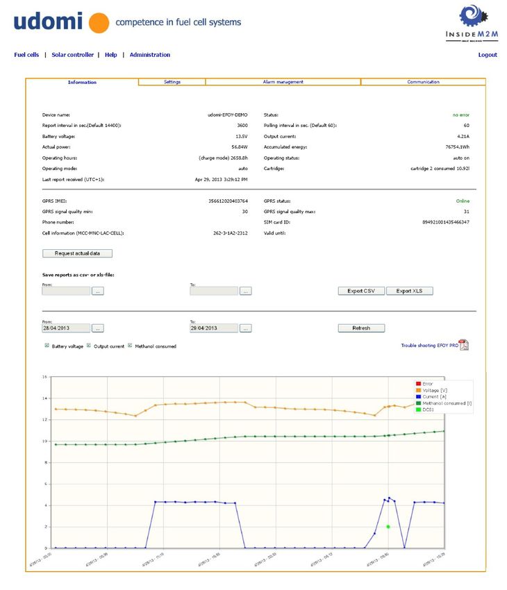
udomi GmbH Hochfeldstraße 8 D-74632 Neuenstein Germany Phone: +49-7942-9420891 Fax: +49-7942-9420898 email: sales@udomi.de www.udomi.de Operation Manual GSM-2 (GPRS Standard Mode) Summary page After successful login at the udomi-off-grid-monitor the following screen will be displayed. The start page displays a brief status summary for your EFOY Pro fuel cell system/s. Other menues available are solar controller, help and administration. After clicking on one of the EFOY Pro devices in the summary page, the following detailed status information page is displayed. On the top of this page the following tabs can be selected: - Information - Settings - Alarm Management - Communication Similar information is available in the solar controller menue
udomi GmbH Hochfeldstraße 8 D-74632 Neuenstein Germany Phone: +49-7942-9420891 Fax: +49-7942-9420898 email: sales@udomi.de www.udomi.de Operation Manual GSM-2 (GPRS Standard Mode) Information The Information page provides detailed data about the current status of the fuel cell or solar charge controller. Historical data can be provided in Excel or csv format using the report generation function. The key data such as battery voltage and charge current are displayed in graphical format as well. 27
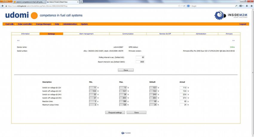
udomi GmbH Hochfeldstraße 8 D-74632 Neuenstein Germany Phone: +49-7942-9420891 Fax: +49-7942-9420898 email: sales@udomi.de www.udomi.de Operation Manual GSM-2 (GPRS Standard Mode) Settings The Settings menue allows the configuration of several important values of the GSM-2 modem. In order to make changes to these values the GSM-2 modem has to be online. Report Interval This parameter defines how often the GSM-2 modem sends a report to the udomi-off-grid-monitor website. Default value is 3600 seconds/1h. With these default settings the data traffic of the GSM-2 modem is app 2Mbyte/month (10kB package size). When reducing the report interval, the data traffic generated will increase slightly. Polling Interval This parameter defines how frequently the GSM-2 modem communicates with the EFOY Pro fuel cell. The default value is 60 seconds. With each communication between GSM-2 and EFOY Pro the GSM-2 modem verifies if an error has occurred. In case of an error the GSM-2 will instantly send an alarm message to all email/SMS addresses listed in the alarm management folder.
udomi GmbH Hochfeldstraße 8 D-74632 Neuenstein Germany Phone: +49-7942-9420891 Fax: +49-7942-9420898 email: sales@udomi.de www.udomi.de Operation Manual GSM-2 (GPRS Standard Mode) Alarm Management In the Alarm Management menue the recipients for the various alarm types can be entered. The system offers the following 3 alarm types: - Cartridge Low (alarm message will be send when FS1 Fuel sensor detects low fuel cartridge or if EFOY PRO switches to another Methanol cartridge) - Error (error of EFOY Pro fuel cell system) - Voltage (voltage drops below alarm limit voltage) The alarm messages can be sent via SMS or Email. While the alarm sent via email is free of charge, the alarm sent via SMS will be charged separate by your SIM card provider. To configure SMS alarms the GSM-2 needs to be online. 29
udomi GmbH Hochfeldstraße 8 D-74632 Neuenstein Germany Phone: +49-7942-9420891 Fax: +49-7942-9420898 email: sales@udomi.de www.udomi.de Operation Manual GSM-2 (GPRS Standard Mode) Communication The Communication menue allows to communicate directly with the EFOY Pro fuel cell system. By entering the command “?” the EFOY Pro system will list the complete command set. More details about these commands can be found in the Help menue The communication with EFOY Pro is very helpful to fix problems and optimize the settings of the EFOY Pro system for your application.
udomi GmbH Hochfeldstraße 8 D-74632 Neuenstein Germany
Phone: +49-7942-9420891 Fax: +49-7942-9420898 email: sales@udomi.de www.udomi.de
Operation Manual GSM-2 (GPRS Standard Mode)
Administration
As a registered user of the udomi-off-grid-monitor internet portal you have access to the following
administration functions:
– Account → Enter/modify account informations
– Change Password → change Login password
– Name Device → modify device name for GSM-2 modems
– Device SIM PIN → activate/deactivate PIN verification, change PIN
ATTENTION: Be careful when changing the PIN of your SIM card. Make sure the GPRS Signal quality
is min 10 (see Information menue) to avoid transmission problems between GSM-2 and udomi-off-
grid-monitor website. In case the communication of the PIN data fails the GSM-Modem may go offline.
In this case you need to remove the SIM Card and enter the Superpin in order to get the GSM-2
online again.
31udomi GmbH Hochfeldstraße 8 D-74632 Neuenstein Germany Phone: +49-7942-9420891 Fax: +49-7942-9420898 email: sales@udomi.de www.udomi.de Operation Manual GSM-2 with SS-MPPT-15L (solar charge controller) GSM-2 und GSM-GPS-2 support for SS-MPPT-15L GSM-2 and GSM-GPS-2 support remote monitoring for EFOY Pro fuel cells or the SS-MPPT-15L solar charge controllers. Both the EFOY Pro and SS-MPPT-15L offer a serial interface which can be connected with the GSM-2 serial port. Required accessories to connect GSM-2/GSM-GPS-2 with the SS-MPPT-15L: Meterbusadapter (MSC adapter) and serial connection cable Step 1: Functional description DIP Switch Position Switch DIP Switch of SS-MPPT-15L No.4 in “ON “ Position Step 2: Connect GSM-2/GSM-GPS-2 with SS-MPPT-15L as shown above. Step 3: Insert SIM Card into GSM-2/GSM-GPS-2 modem Step 4: Connect supply power to GSM-2/GSM-GPS-2 and SS-MPPT-15L (12 or 24V batterie) Step 5: Login into udomi-off-grid-monitor-portal using your login user name and password. www.m2mgate.de/udomi/ User: xxxx Pass: xxxx Step 6: After login to the udomi-off-grid-monitor portal select menue „solar charge controller“. Your SS-MPPT-15L device will appear in the „solar charge controller“ tab. In case your SS-MPPT-15L device appears under the „fuel cell“ menue, please make shure the SS-MPPT-15L is connected as decribed above. It may take a view minutes til the GSM-2 has detected that the SS-MPPT-15L is connected. Clicking on the device name will get you into the menue „information“ with details on the SS-MPPT-15L status. In the „alarm management“ folder you can configure alarm messages and the „communication“ folder lets you connect/disconnnet load output and solar input of the SS-MPPT-15L LOAD CONNECT: Connects load output LOAD DISCONNECT: Disconnects load output CHARGE CONNECT: Connects the solar input CHARGE DISCONNECT: Disconnects solar input RESET: Resets the SS-MPPT-15L (software and timer reset)
udomi GmbH                   Hochfeldstraße 8               D-74632 Neuenstein             Germany
Phone: +49-7942-9420891      Fax: +49-7942-9420898          email: sales@udomi.de          www.udomi.de

Operation Manual GSM-2 with SS-MPPT-15L (solar charge controller)

• Information
The information menue shows the data provided by the solar charge controller. Key data such as
battery voltage, load current and charge current are monitored and also displayed in the graph below.
The time interval of the graph per default shows the data of the last 2 days, individual time intervalls
can be selected as well.

• Communication
The communication menue allows you to switch on/off the load output of the SS-MPPT-15L solar
charge controller. You may also electrically disconnect/connect the solar modules or Reset the solar
charge controller.

33
udomi GmbH                 Hochfeldstraße 8               D-74632 Neuenstein          Germany
Phone: +49-7942-9420891    Fax: +49-7942-9420898          email: sales@udomi.de       www.udomi.de

Operation Manual GSM-2 with MUX-2 (Energy Manager)

MUX-2 connects EFOY PRO and SS-MPPT-15L with GSM-2 modem

With the MUX-2 device users of the GSM-2 modem can now remotely monitor EFOY PRO fuel cell
and the SS-MPPT-15L solar charge controller together. With this solution the user has all
informations of his off grid power system available on the the udomi off grid monitor website.
Battery voltage, load current, solar input current,fuel cell charge current and many other
informations are available to monitor and optimize your off grid power system.

Step 1:
 Functional description                            DIP Switch Position
Switch DIP Switch of SS-MPPT-15L No.4 in “ON “
Position when using the MUX-2 device.

Step 2:

Connect GSM-2 via MUX-2 with EFOY-PRO and SS-MPPT-15L as shown above. GSM-2 will
automatically detect if MUX-2 is connected. When the MUX-2 is detected by the GSM-2 modem the
GSM-2 modem will be listed in the „Energy Manager“ tab.
udomi GmbH                  Hochfeldstraße 8               D-74632 Neuenstein             Germany
Phone: +49-7942-9420891     Fax: +49-7942-9420898          email: sales@udomi.de          www.udomi.de

Operation Manual GSM-2 with MUX-2 (Energy Manager)

• Information
When connecting the EFOY PRO and the SS-MPPT-15L via the MUX-2 to the GSM-2 modem you will
get both the data from the fuel cell and the solar charge controller displayed in the information menue
of the EnergyManager tab. Fuel cell data is shown on the left side and solar charge controller data on
the right side. Below you have a graph showing the historical data for EFOY PRO and SS-MPPT-15L.
The time interval of the graphs are user selectable.

35
udomi GmbH                   Hochfeldstraße 8               D-74632 Neuenstein                   Germany
Phone: +49-7942-9420891      Fax: +49-7942-9420898          email: sales@udomi.de                www.udomi.de

Operation Manual GSM-2-GPIO

GSM-2-GPIO

The GSM-2-GPIO has a external connector
interface that provides the user with relais outputs
that switch in case EFOY Pro generates an Error
Message or Methanol fuel needs replaced.

Inputs (alarm input):
Pins 2-7 can be configured as alarm inputs. As
soon as the input voltage rises above 5 Volt the
alarm will be triggered. The maximum input
voltage is limited 30VDC. Connect Pin 12 as
common ground for all 6 inputs. Alarms can be
configured via the udomi-off-grid-monitor portal
using the GPIO Menue
Output 1:                                                                  GSM-2-GPIO
The relais output 1 is shortened if EFOY Pro has an
ERROR or the battery voltage drops below a              Pin     Function               Description
predefined value. This value can be set in the          1            -                      NA
udomi-off-grid-monitor webinterface in the menue
„ALARM- MANAGEMENT“. The relais output 1 is             2        Input 1            Input 1 high active
shortened as long as the Alarm event is present.        3        Input 2            Input 2 high active

Output 2:                                               4        Input 3            Input 3 high active
If the Fuel Low Sensor FS1 is attached to EFOY Pro      5        Input 4            Input 4 high active
the relais output 2 gets shortened when the
Methanol fuel level drops below the FS1 position.       6        Input 5            Input 5 high active
The output 2 opens as soon as the FS1 detects           7        Input 6            Input 6 high active
Methanol again (full Methanol cartridge is
                                                        8       Output 1         Relais output 1:
installed).
                                                                              ERROR EFOY Pro or Low
In case the Duocartswitch DCS1 is connected with
                                                                                  Voltage Alarm
the EFOY Pro device, the output 2 is shortened          9       Output 1
when the DCS1 switches from 1 Methanol cartridge
to the other. The relais output 2 stays closed for 60
                                                        10      Output 2          Relais output 2:
seconds and then switches back to open position
                                                                               Cartridge low (FS1) or
(Pin 10 and 10 disconnected).
                                                                                switch fuel cartridge
The 60 seconds are equal to the Polling Intervall,      11      Output 2
                                                                                       (DCS1)
configured in the SETUP Menue of the udomi-off-
grid-monitor interface. If the polling intervall is     12           -              Common Ground
changed then this will also change the time the
output 2 is closed.

The relais outputs will also be switched in case the
GSM-2-GPIO is operated without SIM card.

The maximum load capability of the relais outputs
1 and 2 is limited to 500mA@30V.
udomi GmbH Hochfeldstraße 8 D-74632 Neuenstein Germany Phone: +49-7942-9420891 Fax: +49-7942-9420898 email: sales@udomi.de www.udomi.de Operation Manual GSM-2-GPIO The Information menue for the GSM-2-GPIO modem includes informations about the status of the 6 digital inputs and the 2 output relais (see highlighted area). With the Deactivate Button you can make the the configured IO alarms configured in the Alarm management inactive. With the Switch output manually button is on the Output 1 and 2 can be switched on and off manually. With this feature you may switch on and off remote devices such as cooling fan or heating (use external relais if load current is >500mA) .If the Switch output manually button is off the outputs 1 and 2 are triggered based on the alarm events described on page 29. 37
udomi GmbH                   Hochfeldstraße 8                D-74632 Neuenstein            Germany
Phone: +49-7942-9420891      Fax: +49-7942-9420898           email: sales@udomi.de         www.udomi.de

Operation Manual GSM-2-SMS (SMS Mode)

Description:                                         The following commands are available:
In standard mode (GPRS) the GSM-2 system             1. Alarm when an “ERROR“ occurs at the EFOY
communicates via a public APN with the udomi-        Pro device
off-grid-monitor-portal. This communication is       “addalarm“: Send alarm SMS message when an
based on the TCP-IP protocol and the udomi-          ERROR occurs at EFOY Pro fuelcell
off-grid-monitor portal provides an easy to          “delalarm“: Delete alarm
operate and comfortable operation interface.         Example:
For applications, where a GPRS network is not        12345:addalarm:0170123333 – Send alarm SMS
available, or the user prefers that the GSM-2        to mobile number 0170123333 when an ERROR
modem operates in regular CSD mode, the SMS          occurs at the EFOY Pro fuel cell
mode is available as an option. In SMS mode          12345:delalarm:0170123333 – No longer send
the basic functions of the GSM-2-SMS can be          Alarm message in case of ERROR at EFOY Pro to
configured via SMS commands. Alarms are also         mobile number 01700123333 is deleted
sent via SMS only. GSM-2-SMS devices can be
upgraded to GSM-2 (GPRS-Standard Mode) on            2. Alarm when the Methanol level falls below a
request (info@udomi.de).                             certain level (requires FS1 fuel cartridge sensor)
                                                     “addcart“: Send alarm SMS message when
                                                     Methanol level drops below FS1 sensor.
The GSM-2-SMS device offers 3 different              “delcart”: Delete Methanol low alarm
alarms:                                              Example:
    4. Alarm when an “ERROR“ occurs at the           12345:addcart:0170123333 – Send alarm SMS
        EFOY Pro device                              message to mobile number 017012333 when
    5. Alarm when the Methanol level falls           Methanol level drops below FS1 sensor.
        below a certain level (requires FS1 fuel     12345:delcart:0170123333 – No longer send
        cartridge sensor)                            Alarm SMS in case of low Methanol level to phone
    6. Alarm when the battery voltage drops          number 0170123333
        below a certain value (trigger voltage
        can be programmed)                           3. Alarm when the battery voltage drops below a
                                                     certain value (trigger voltage can be
Command overview GSM-2-SMS:                          programmed)
In SMS mode the GSM-SMS modem is
configured with SMS commands. The SMS                Before using this alarm the trigger voltage has to
commands are described below:                        be set using the “setvolt” command.
                                                     “setvolt”: When the battery voltage drops below
xxxxx:cmd:value                                      this value the GSM-2-SMS modem sends an alarm
xxxxx: last 5 digits of the IMEI number of the       message SMS (default value is 0.0).
GSM-2-SMS modem (IMEI is printed on the              “addvolt”: Send alarm SMS message when
GSM-2-SMS device). This IMEI number is               batters drops below value set with “setvolt“
unique for any GSM-2-SMS modem and used as           command.
a password.                                          “delvolt”: Delete low voltage alarm
cmd: command                                         Example:
value: command value                                 12345:setvolt:11.8 – Set low voltage alarm
                                                     trigger to 11.8 Volt (use decimal point!)
                                                     12345:addvolt:0170123333 – Send alarm SMS
                                                     message to 0170123333 when battery voltage
                                                     drops below 11.8 Volt.
                                                     12345:delvolt:0170123333 – No longer send
                                                     Alarm SMS in case of low battery voltage to
                                                     phone number 0170123333
udomi GmbH Hochfeldstraße 8 D-74632 Neuenstein Germany
Phone: +49-7942-9420891 Fax: +49-7942-9420898 email: sales@udomi.de www.udomi.de
Operation Manual GSM-2-SMS (SMS Mode)
4. Master-alarm 9. Confirmation SMS
The “addall“ command sends an Alarm SMS For each successfully send command SMS the
message if any of the 3 alarms type occurs (ERROR GSM-2-SMS will send a SMS confirmation
EFOY Pro, low Methanol or low battery voltage). back to the sender. If you do not receive the
“addall”: Send alarm SMS message when any of the confirmation SMS please verify if your
3 Error type occurs password or command has been entered
“delall”: Delete Master Alarm correctly.
Example:
12345:addall:0170123333 - Send alarm SMS 10. EFOY Pro status request via SMS
message to 0170123333 when Master Alarm occurs. You can request the actual status of the
12345:delall:0170123333 – No longer send Master EFOY Pro fuel cell via the following
Alarm SMS to phone number 0170123333 command.
Example:
5. Polling interval 12345:sfc:sfc – the GSM-2-SMS will return
The polling interval describes every how may the current status of the EFOY Pro fuel cell
seconds the GSM-2-SMS modems requests status via SMS to your mobile phone.
information from the EFOY Pro fuel cell. Default Example:
value is 60 seconds. As soon as the EFOY Pro fuel SFC>SFC
cell reports an error for 2 consecutive polling battery voltage: 12.08V
requests, GSM-2-SMS will treat this as an alarm output current: 0.0A
event. If required the polling interval can be operating time: 5.8h
modified using the “setpoll” command: operating state: error
“setpoll“ Polling interval in seconds (DEFAULT 60s) operating mode: auto
Example: please change fuel cartridge
cartridge level below sensor
12345:setpoll:120 – Set Polling interval to 120
seconds SFC>
6. DEFAULT (Set modem parameters to factory 11. Terminal connection with EFOY Pro using
default values) the GSM-2-SMS
The “default” command deletes all alarms and
resets the GSM-2/GSM-GPS-2 modem back to The GSM-2-SMS modem offers a direct
factory default values. connection to the data interface of the EFOY
Example: Pro device using a standard terminal program
12345:default: – deletes all alarms and resets to such as Hyperterminal. To establish such a
factory default parameters communication please follow the following
steps:
7. GPS (get GPS coordinates from modem – GSM- Establish a dial up connection between the
GPS-2 only) GSM-2-SMS modem and your analog PC
The “gps” command triggers the GSM-GPS-2 modem. Use communication settings 9600
modem to send current GPS coordinates via SMS. bits/s, 8bits/byte, 1 stop bit, no parity, no
Example: flow control.
12345:gps: – returns the current GPS coordinates of Example:
the modem location via SMS ATD016045678
After a successful connection with the GSM-
8. RESET (EFOY Pro fuel cell) 2-SMS modem (CONNECT…) please enter the
If an ERROR occurs at the EFOY Pro fuel cell (for last 5 digits of the GSM-2-SMS IMEI number.
example “Please check exhaust tube”) it is possible In case the authorization has been successful
to restart the EFOY Pro device by sending the “OK“ will be prompted and a direct
RESET command. In many cases it is possible to communication link has been established with
restart the EFOY Pro remotely. the serial data communication interface of
Example: EFOY Pro (see more details in the manual
12345:reset: - RESET EFOY Pro fuel cell (same UM2). In case the authorization fails “bye“
function as pushing the RESET button of the EFOY will be prompted and the connection is
Pro device). cancelled by the GSM-2-GSM modem.
39Sie können auch lesen