Bedienungsanleitung GSM Alarm
←
→
Transkription von Seiteninhalten
Wenn Ihr Browser die Seite nicht korrekt rendert, bitte, lesen Sie den Inhalt der Seite unten
Bedienungsanleitung GSM Alarm
Das GSM* Alarm dient zur Überwachung der Zaunspannung. Bei Unterschreiten der Grenzwerte kann
eine SMS auf bis zu 5 gespeicherte Telefonnummern gesendet werden.
Es kann unter Verwendung des GSM‐Netzwerkes über ein gewöhnliches Mobiltelefon mit SMS‐Befehlen
gesteuert werden. Sie benötigen dazu eine SIM‐Karte eines Mobilfunkanbieters (nicht im Lieferumfang
des GSM Alarm enthalten).
Das GSM Alarm verfügt über zwei Ausgänge (A + B), die je nach Konfigurierung beide als „schaltbare
Ausgänge“ oder einer davon als ALARM‐Ausgang genutzt werden können.
Optional und abhängig von der Nähe zum Weidezaungerät kann mittels GSM Alarm das Weidezaungerät
EIN/AUS‐geschalten werden.
Das GSM Alarm kann mit 230V‐Netzadapter, mit einer 9V‐Batterie oder 12V‐Akku betrieben werden. Bei
9V‐ oder 12V‐Betrieb kann auf die Spanungsversorgung des Weidezaungerätes zugegriffen werden
(Anschluss an ERDE und ZAUN mittels Erdspießkabel E264355 und Herzklemme E203925, im
Lieferumfang enthalten)
Platzierung des GSM‐Alarm kann direkt bei der Zaunanlage
z.B. an einem Zaunpfahl erfolgen. Wir empfehlen, das Gerät
gegen direkte Sonneneinstrahlung zu schützen.
* GSM = Global System for Mobile Communications BA‐1150‐Version 2013.2
[1]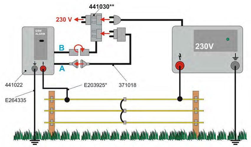
Inhaltsverzeichnis

1   Kurzübersicht einiger gängiger Gerätekombinationen                    4
2   Ersteinrichtung SIM-Karte:                                            6
    2.1      SIM-Karte kaufen                                             6
    2.2      Neue SIM-Karte freischalten                                  6
    2.3      SIM-Karte in das GSM Alarm einlegen                          6
    2.4      Systembatterie einsetzen                                     7
    2.5      Initialisierung/LED-Beschreibung                             7
3   Telefonnummern                                                        8
    3.1     Telefonnummer mit SMS-Alarmmeldung konfigurieren (Standard)   8
    3.2     Telefonnummer ohne SMS-Alarmmeldung konfigurieren             8
    3.3     Telefonnummer löschen                                         9
4   Alarmschwellen einstellen                                             10
    4.1    Zaunspannung                                                   10
           4.1.1   Alarmschwelle Typ A                                    10
           4.1.2   Alarmschwelle Typ B                                    11
           4.1.3   Alarmschwelle Typ C                                    11
    4.2    9V / 12V Versorgungsspannung                                   12
    4.3    Systembatterie                                                 12
5   Anschlüsse A und B                                                    13
    5.1    Technische Funktionsbeschreibung der Anschlüsse                13
           5.1.1   Anschluss A (DC-Eingang/Ausgang)                       13
           5.1.2   Anschluss B (Relais)                                   13
    5.2    Funktionsübersicht                                             13
    5.3    Konfiguration einiger Gerätekombinationen                      14
           5.3.1   Fall 1 (230V)                                          14
           5.3.2   Fall 2 (230V)                                          15
           5.3.3   Fall 3 (230V)                                          16
           5.3.4   Fall 4 (12V)                                           17
           5.3.5   Fall 5 (12V)                                           18
           5.3.6   Fall 6 (9V)                                            19
6   GSM-ALARM Ein-/Ausschalten                                            20
    6.1   Einschalten GSM-ALARM                                           20
          6.1.1    Per SMS                                                20
          6.1.2    Per Anruf                                              20
    6.2   Ausschalten GSM-ALARM                                           20
          6.2.1    Per SMS                                                20
          6.2.2    Per Anruf                                              20
7   Modus „Ein-/Ausschalten per Anruf“ freigeben oder sperren             21
    7.1    Freigeben                                                      21
    7.2    Sperren                                                        21
    7.3    Quittier-Methode bei Anruf                                     21
           7.3.1    Ton (= Werkseinstellung)                              21
           7.3.2    Rückruf                                               21

                                                   [2]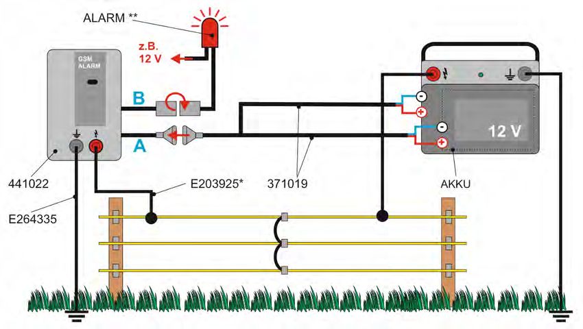
8    Gerätenamen                                     22
9    Verschiedenes                                   23
     9.1     Statusabfrage                           23
     9.2     Statusanzeige                           23
     9.3     ALARM SMS-Meldung                       23
     9.4     Alarmzustand zurücksetzen               24
     9.5     Guthaben auf SIM-Karte abfragen         24
     9.6     Werkseinstellung                        24
     9.7     Technische Daten:                       25
     9.8     Serviceadressen:                        25
10   Befehlsübersicht                                26
11   Lieferumfang                                    28

                                               [3]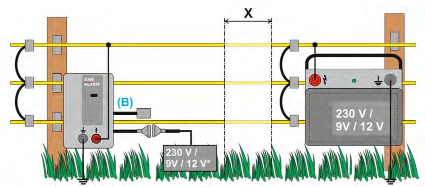
1       Kurzübersicht einiger gängiger Gerätekombinationen
Fall 1 – (230 V)

SMS‐Alarm + 230V‐Weidezaungerät, siehe Punkt 5.3.1

Fall 2 – (230 V)

SMS‐Alarm + 230V‐Weidezaungerät + optisch/akustischer Signalgeber, siehe Punkt 5.3.2

Fall 3 – (230 V)

SMS‐Alarm + 230V‐Weidezaungerät + 230V‐EIN/AUS‐Schaltadapter, siehe Punkt 5.3.3

                                               [4]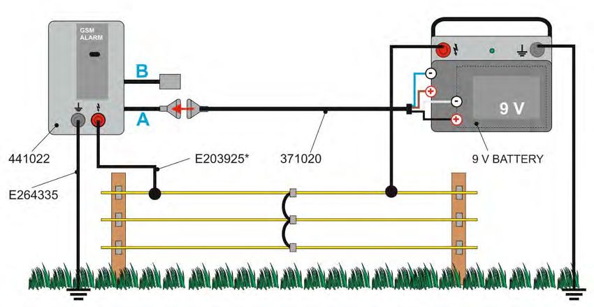
Fall 4 – (12 V)

SMS‐Alarm + 12V‐Weidezaungerät + EIN/AUS‐Schalten möglich, siehe Punkt 5.3.4

Fall 5 – (12 V)

SMS‐Alarm + 12V‐Weidezaungerät + EIN/AUS‐Schalten möglich + optisch/akustischer Signalgeber,
siehe Punkt 5.3.5

Fall 6 – (9 V)

SMS‐Alarm + 9V‐Weidezaungerät + EIN/AUS‐Schalten möglich, siehe Punkt 5.3.6
                                              [5]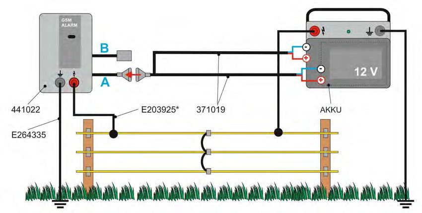
2      Ersteeinrichtun
                     ng SIM‐Karte:

2.1
  1    SIM‐K
           Karte kaufe
                     en

      (z.B. Prepaid‐Kartte) kaufen bzw.
                                   b    vorhanndene SIM‐K
                                                        Karte verwe
                                                                  enden

      Bitte aachten Sie darauf,
                        d       dasss Sie mit Ihhrem ausge
                                                         ewählten Neetzbetreibeer für die SIIM‐Karte Ihres
      neuenn GSM Alarm  m am Einsaatzort eine starke Nettzqualität (m
                                                                    mehr als 1//3 der Emp pfangsleistung)
      habenn. Platzieren
                       n Sie kein Metall
                                  M       oder andere leittende Mate
                                                                   erialien in d er Nähe dees GSM Alarrm,
      da dies zum Verluust der Netzzwerkverbinndung führe en kann.

               Hinweis zuz Prepaid‐‐Karten: Ess liegt am jeweiligen n Kartenanbbieter, ob die Karte so
               geschaltett ist, dass sie
                                     s bei abgeelaufenem Guthaben weiterhin aangerufen werden kann.
               In der Reggel wird die
                                    es der Fall seein.
               Das GSM M Alarm kaann in diessem Fall Befehle
                                                          B         mpfangen u nd ausführen, aber bei
                                                                   em
               fehlendemm Guthaben   n keine Rückkmeldung in
                                                           n Form von Anruf oderr SMS durch
                                                                                          hführen.

2.2
  2    Neuee SIM‐Karte freischalte
                                 en

      Neue SSIM‐Karte beim
                      b    Netzbe etreiber freeischalten
      Inform
           mationen zu
                     ur Freischalttung bitte bbeim Netzannbieter einh
                                                                    holen!

               WICHTIG: PIN Ihrer neuen
                                  n      oder der bereitss vorhandenen GSM S IM‐Karte mittels
                                                                                       m
               Mobiltele
                       efon in den Sicherheitsseinstellunggen vor Inbe
                                                                     etriebnahm
                                                                              me des GSM
                                                                                       M Alarm
               auf 6789 ändern.
                        ä

2.3
  3    SIM‐K
           Karte in dass GSM Alarm
                                 m einlegen

      SIM‐Kaarte wie abgebildet in den SIM‐Kaarten‐Slot, siehe
                                                         s     Unterseite GSM‐G
                                                                              Gerät, einse
                                                                                         etzen.

      SIM‐Kartte einsetzen                        Halterung schließen und
                                                                        d verriegeln (LO
                                                                                       OCK)

               SIM‐Kartee sollte beim
                                    m Mobilteleffon und GSM‐Alarm vo
                                                                   om selben A
                                                                             Anbieter seiin (Kosten
               sind dann niedriger bzw.
                                    b   entfalleen).

                                                   [6]
2.4
  4      Systeembatterie einsetzen

Po
 olung gemäß
           ß Abbildung beachten!
                       b                          Batteeriefachdeckkel schließen
                                                                               n

2.5
  5      Initialisierung/LED‐Beschre
                                   eibung

Naachdem die P Punkte 2.1 biis 2.4 durchggeführt wurdden, beginnt das GSM‐Ala
                                                                            arm sich zu iinitialisieren..
Wäährend diesees Vorgangess blinken die LED’s gemä ß nachfolgen  nder Beschre
                                                                            eibung.
Zeitgleich zeigtt das orange Blinken, ob eine GSM‐N etzverbindung vorhande  en ist (Takt cca. 3,0 sec.) oder
                                                                                                        o    nicht (TTakt
ca.. 0,8 sec.)

                      Initialissierung GSM‐A
                                           ALARM + Zaunnimpuls                GSM‐Netzverb
                                                                              G          bindung
LEED GSM‐ALA
           ARM
                      Beschrreibung „blinkken“                                Beschreibung
                                                                              B            „„blinken“
Initialisierung
                      rot   g
                            grün weiß blau Abwecchselnd                       orange
                                                                              o
dees GSM‐ALRAM  M
                                                                                       Takt 00,8 sec. =
Initialisierung                                                                        KEINEE Netzverbindung
                      AUS AUS      AUS AUS Aus                                orange
                                                                              o
 bgeschlossen O
ab              OK
                                                                                       oder
Initialisierung
                      rot   AUS weiß AUS 1x weißß, 10x rot                    orange
                                                                              o
fehlgeschlagen                                                                         Takt 33,0 sec =
                                                                                       Netzvverbindung OK
                                                                                                        K
Zaaun                                            blinkenn im Takt
                      AUS grün
                          g        AUS AUS                                    orange
                                                                              o
anngeschlossen                                   der Zauunimpulse

Za
 aun angesschlossen, =>
Ne
 etzverbinddung OK =>

                  Nachdem die Ersteinrichtung deer SIM‐Kartte abgeschlo
                                                                      ossen wurdde, sollten alle
                                                                                            a weitereen
                  Konfigura
                          ationen dire
                                     ekt an dem dafür vorge esehenen Betriebsort
                                                                     B           vvorgenomm men werdenn.

                  Während der Konfigu uration darrf ein weiterer SMS‐Be
                                                                      efehl frühesstens 10 secc. nach der
                  erfolgten Bestätigun
                                     ng des voranngegangen  nen SMS‐Beffehls gesenndet werden  n.

                                                            [7]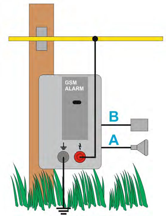
3         Teleffonnumm
                     mern
                 Das GSM Alarm
                           A      musss mit mindeestens einerr Telefonnummer und zzwei weiterren
                 Parametern per SMS konfigurierrt werden. Es E können max.
                                                                        m 5 Teleffonnummern, auch mit
                 unterschieedlichen Konfigurationnen, hinterle
                                                             egt werden.

      1. Parameeter: legt fesst, an welchhe Telefon‐ Nr. im Alarm
                                                                mfall eine SMS
                                                                           S    gesenddet werden soll.
      2. Parameeter: legt fesst, ob im Alarmfall einee SMS gesendet werde  en soll (y=JA
                                                                                       A oder n=NE
                                                                                                 EIN)
      3. Parameeter: legt fesst, mit welccher Verzöggerung in Minuten
                                                              M         (max. 60 min) eeine SMS ge
                                                                                                 esendet
      werden sooll.

                 Aus Sicherheitsgründ den sind beestimmte Ko
                                                           ommandos nur mit Addministrato   orrechten
                 erlaubt. Administrat
                          A           ionsrechte hat automaatisch das Telefon
                                                                      T       mitt der zuerst
                 gespeicheerten Tel. Nr.

                 Telefonnuummer imm  mer mit ausggeschriebenner Internattionaler Vorrwahlnumm
                                                                                            mer (z.B. 004
                                                                                                        49
                 für Deutscchland; 0045 für Dänemmark, usw.) angeben.
                 Jede SMS hat z.B. folggendes Formmat einzuhaalten:
                 Kommand  do:Parameter,Parametter,Parametter
                 D.h. nach dem Komm  mando stehtt ein Doppe elpunkt, zwischen den PParametern
                                                                                            n ein Komm ma.
                 Es dürfen keine Leerzzeichen entthalten sein.

3.1
  1       Telefo
               onnummerr mit SMS‐A
                                 Alarmmeldu
                                          ung konfigu
                                                    urieren (Standard)

         Beispiel:      Diee deutsche Telefonnummmer 0123 45678901 soll
                                                                      s unmitteelbar nach Auftreten
                                                                                          A
                        ein
                          ner Alarmsittuation per SMS inform
                                                           miert werde
                                                                     en.

         1. Parameter:          004912 2345678901 (Tel‐Nr. inkl. internationnale Vorwahll)
         2. Parameter:          y (= yess – Ja, es solll eine SMS‐M
                                                                  Meldung gese
                                                                             endet werdeen)
         3. Parameter.          0 (= 0 Minuten
                                       M          – d. h. keine zeitliche
            Verzögerung)

         SMS:           addnumber:0049123456678901,y,0
         Antwoort:      Phone No. 004
                                    49123456778901 added
                                                       d

3.2
  2       Telefo
               onnummerr ohne SMS‐Alarmmeld
                                          dung konfiggurieren

          Grund d: Sie wünschen nur eiine Alarmm meldung mittels
          optisccher/akustischer Signaaleinheit (An
                                                  nschluss B).

         SMS:           addnumber:0049123456678901,n,0
         Antwoort:      Phone No. 004
                                    49123456778901 added
                                                       d

                                                        [8]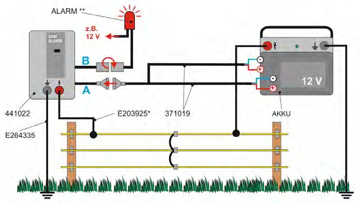
3.3
  3   Telefo
           onnummerr löschen

      Beisp
          piel:   Diee Telefonnu
                               ummer 0049912345678901 soll gelöscht werdden
      SMS:        delnumber:00 049123456778901
      Antw
         wort:    Phone No. 004 49123456778901 delete
                                                    ed

                  Wiird versehentlich die z uerst einge
                                                      egebene Telefon‐Nr. geelöscht, oder wurde
      diesee      falsch programmmiert, muuss das GSM M‐Alarm auf die Werksseinstellungg (siehe 9.6
                                                                                                  6)
                  zurrückgesetztt werden.

                                               [9]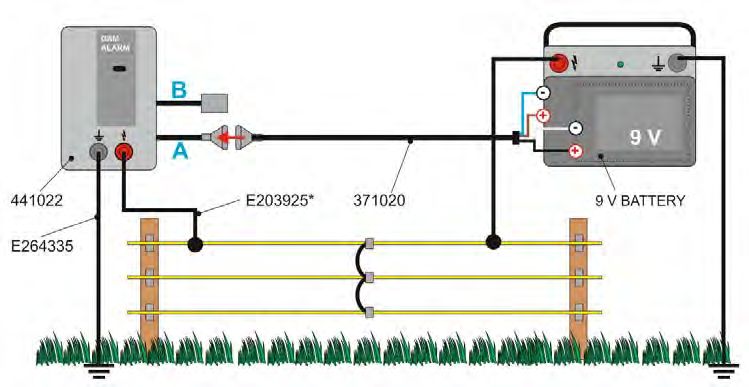
4       Alarm
            mschwellen einstelllen

4.1
  1     Zaunsspannung

        Die A
            Alarmschwelle der Zaunnspannung ist werkseittig auf 3,0 kV
                                                                     k (3000 Voolt) eingesteellt. Dieser
        Wert soll abhänggig vom Gerrätestandorrt und Zaun            wischen 2,55 kV bis 8,0 kV eingesteellt
                                                         nsituation zw
        werden. Bei Unterschreitunng der eingeestellten Sch
                                                          hwelle wird
                                                                    d Alarm ausggelöst (SMS‐Meldung
        und/ooder option
                       naler Signalggeber)

        Beisp
            piel:     Zauunspannungsalarm solll auf 4,5 kV
                                                         V eingestelltt werden
        SMS:          fen
                        ncealarm:4.5
                      unbedingt beaachten !!! D
                                              Den Dezimal als PUNKT T schreiben
        Antw
           wort:      thee commandd fencealarmm:4.5 acceppted

              Nach Konffiguration und
                                  u Inbetrieebnahme de   es GSM Alarrm sollte beei guten
              Zaunbedinngungen (ke ein Bewuchhs, gute Isolaation, gute Verbindunggen/Erdungg, usw.) an
              verschiedeenen Punkten in der Zaaunanlage ein
                                                          e Kurzschluss (Verbinndung von Zaundraht
                                                                                            Z          z
                                                                                                       zur
              Erde) „sim
                       muliert“ werrden um zu testen, ob die passend  de Alarmschhwelle defin
                                                                                            niert wurdee
              und somitt der Alarm aktiviert wiird.
              Achtung: Eine zu hohhe Alarmsch hwelle kann n Fehlalarmm auslösen. Z.B. kann sich
                                                                                            s die
              Zaunspannung allein n durch unteerschiedlichhe Witterun ng verände rn/reduzieren. Zu geriing
              gewählte Alarmschw wellen führeen im Gegenzug ggf. zu   u ausbleibeenden Melddungen.

4.1
  1.1       mschwelle Ty
        Alarm          yp A

Daas GSM‐Alarrm und das Weidezaun   ngerät sind örtlich beie
                                                           einander. De
                                                                      er Zaundrahht zwischen
                                                                                           n den beiden
                                                                                                      n
Ko
 ontaktpunktten ist nichtt getrennt = Alarmschwwelle soll in diesem Fall höher seinn.

Alaarmschwelle : z.B. 6,0 kV ( 6000 Volt
                                    V )

                                                    [10]
4.1.2 Alarmschwelle Typ B
Das GSM‐Alarm und das Weidezaungerät sind auch örtlich beieinander, Zaunanfang und –ende jedoch
voneinander getrennt – Alarmschwelle soll in diesem Fall geringer sein.
Alarmschwelle : z.B. 3,0 kV ( 3000 Volt )
4.1.3 Alarmschwelle Typ C
Das GSM‐Alarm und das Weidezaungerät sind örtlich getrennt. Das GSM‐Alarm benötigt eine eigene
Stromversorgung ( 9V, 12V oder 230V). Je weiter das GSM‐Alarm vom Weidezaungerät entfernt am
Zaun angeschlossen ist, desto geringer soll die Alarmschwelle sein.
Alarmschwelle : z.B. X = 10 m : 6,0 kV ( 6000 Volt ) X = 1000 m : 3,0 kV ( 3000 Volt )
X = 100 m : 5,0 kV ( 5000 Volt ) X > 1000 m : 2,5 kV ( 2500 Volt )
X = 500 m : 4,0 kV ( 4000 Volt )
* = 230V Netzadapter, 12V‐Akku oder 9V Weidezaunbatterie, welche vor Regen geschützt werden müssen.
[11]4.2
2 9V / 112V Versorggungsspann
nung
Alarmschwelle passt sicch werkseiti g an die entsprechende Spannunggsversorgun
Die A ng
autommatisch an. Bei Unterscchreitung dder Alarmschwelle wird
d eine SMS‐ Meldung ge
esendet.
Spannnungs‐ Automatische Emppfehlung Anmerkunng
verso
orgung W
Werkseinstellung
fü
ür ALARM
9 Voltt 6,,0 Volt Salinne‐Batterie : 6,0 V je nach Za unsituation n sollte der
Alkaaline‐ Batterrie : 7,0 V Wert ents prechend angepasst
a
werden
12 Vo
olt 122,3 Volt 11,99 V – 12,3 V kann je naach Akku‐Zu
ustand bis
minimal 111,5 V verändert werdeen
piel:
Beisp Diee Alarmschw
welle der Sppannungsve
ersorgung soll auf 12,1 V eingestellt werden
SMS: mbbalarm:12.11
unbedingt beaachten!!! D en Dezimal als PUNKT schreiben
Antw
wort: thee command d mbalarm:112.1 accepted
4.3
3 Systeembatterie
(nichtt einstellbarr )
Die Ü
Überwachun embatterie iist auf 3,6 V eingestelltt. Bei Unterrschreitung dieses
ng der Syste
Wertes wird ein Alarm ausggelöst (SMS‐‐Meldung und/oder
u op
ptionaler Siggnalgeber).
Diee Systembatterie versoorgt das GSM
M‐Alarm beei Verlust deer GSM
Versorgungsspannung füür ca. 48 Stu unden mit Strom.
Die
e Systembaatterie (AKK
KU, Art.‐No.. E268218) muss währrend längerrer
Betriebspauseen aus demm GSM Alarmm entfernt werden, um
m eine Tiefeentladung zu
z
verhindern!
[12]5 Anschlüsse A und B
Funktionsbeschreibung, Statusanzeige und Konfiguration
5.1 Technische Funktionsbeschreibung der Anschlüsse
5.1.1 Anschluss A (DC‐Eingang/Ausgang)
Er dient als Anschluss für die Stromversorgung des GSM‐Alarm (=Eingang).
Mit ihm kann auch ein batteriebetriebenes Weidezaungerät per Anruf oder SMS ein‐
/ausgeschaltet werden (=Ausgang).
5.1.2 Anschluss B (Relais)
‐ nur verwendbar bei 12V oder 230V Betrieb
Werkseitig ist dieser Ausgang deaktiviert.
In Funktion Alarmausgang wird das Relais im Alarmfall eingeschalten (bei 9V Batteriebetrieb
nicht möglich) und bleibt in diesem Zustand bis der Alarm zurückgesetzt (Punkt9.4) wird.
Wird der Ausgang als Schaltausgang konfiguriert, kann in Verbindung mit unserem (Zubehör)
„EIN/AUS Schaltadapter“ Art. Nr. 441030 z. B. ein 230V‐Weidezaungerät per Anruf ein‐
/ausgeschaltet werden.
Beispiel: Relais bei Alarm schalten
SMS: relfunc:al
Antwort: the command relfunc:al accepted
Beispiel: DC Ausgang als Schaltausgang
SMS: dcout:sw
Antwort: the command dcout:sw accepted
5.2 Funktionsübersicht
ALARM möglich über: Ein‐/ Ausschalten Weidezaungerät wird
Spannungs‐
Fall GSM‐ALARM über GSM‐Alarm mit
versorgung SMS‐Alarm Signalgeber (siehe 6.1 und 6.2) Ein‐/ Ausgeschalten
1 X X
230 V 2 X X X
3 X X X
4 X X X
12 V
5 X X X X
9V 6 X X X
[13]5.3
3 Konfiiguration eiiniger Gerättekombinattionen
Die beiden
n SMS‐Befehle müssenn für die verrschiedenen n Fälle imm er durchgefführt werdeen,
außer diesse folgende
e werkseitig en Einstellu
ungen sind noch
n aktiv:
A = dcoutfunc:sw , B = relfuncc:no
5.3
3.1 Fall 1 (230V)
GSM‐‐ALARM Weidezaun
ngerät Zuusatzgeräte
e Funkt ionen
4410222‐230 230 V ‐ SMS‐A
ALARM
Status bzw
w. ALARM‐ Anzeige
A bei:
An‐ konfigu ‐
Beschreibung SMS‐B
Befehl: Power
P ON Pow
wer OFF
schluss rieren aals
(siehe
( Punkt 66.1) (sieh
he Punkt 6.2)
Dcou
ut Spannnungs‐
Schalt‐
versorrgung dcouttfunc:sw
A angeschlossen
ausgangg
Rel Ansch
hluss nicht keine
relfun
nc:no
B belegtt Funktio n
(Poweer ON und Power
P OFF, siehePunktt 6.1)
* E2203925 (Herrzklemme) muss
m nach dden örtliche
en Begebenheiten evtl . durch ein längeres
Kabell ersetzt weerden.
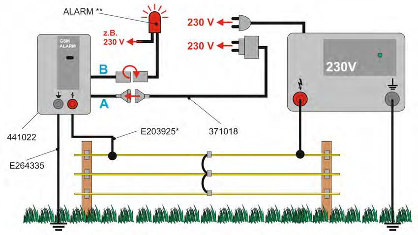
[14]5.3.2 Fall 2 (230V)
GSM‐ALARM Weidezaungerät Zusatzgeräte Funktionen
230 V optisch oder akustischer SMS‐ALARM
441022‐230
Signalgeber (ALARM**) + separater ALARM**
Statusanzeige wenn KEIN Alarm
An‐ konfigu‐ SMS‐Befehl: Alarmanzeige bei ALARM
Beschreibung
schluss rieren als Power ON Power OFF
(siehe Punkt 6.1) (siehe Punkt 6.2)
KEIN Alarm: KEIN Alarm:
Dcout Spannungs‐
Schalt‐
versorgung dcoutfunc:sw
A angeschlossen
ausgang
Alarm: Alarm:
Rel akustisch oder
Schalt‐
optischer relfunc:al
B Signalgeber **
ausgang
(Power ON und Power OFF, siehe Punkt 6.1)
* E203925 (Herzklemme) muss nach den örtlichen Begebenheiten evtl. durch ein längeres
Kabel ersetzt werden.
** optisch bzw. akustischer Alarm muss für diese Anwendung separat dazu bestellt werden.
[15]5.3.3 Fall 3 (230V)
GSM‐ALARM Weidezaungerät Zusatzgeräte Funktionen
230 V 230 V Ein‐ Ausschaltadapter SMS‐ALARM +
441022‐230
441030** Ein‐/Ausschalten
Status bzw. ALARM‐ Anzeige bei:
An‐ konfigu‐
Beschreibung SMS‐Befehl:
schluss rieren als Power ON Power OFF
(siehe Punkt 6.1) (siehe Punkt 6.2)
Dcout Spannungs‐
Schalt‐
versorgung dcoutfunc:sw
A angeschlossen
ausgang
Rel 230 V Ein‐
Schalt‐
Ausschaltadapter relfunc:sw
B angeschlossen
ausgang
(Power ON und Power OFF, siehe Punkt 6.1)
* E203925 (Herzklemme) muss nach den örtlichen Begebenheiten evtl. durch ein längeres
Kabel ersetzt werden.
** 441030 (230V Ein‐/Ausschaltadapter) muss für diese Anwendung separat dazu bestellt
werden.
[16]5.3.4 Fall 4 (12V)
GSM‐ALARM Weidezaungerät Zusatzgeräte Funktionen
‐ SMS‐ALARM +
441022‐12 12 V
Ein‐/Ausschalten
Status bzw. ALARM‐ Anzeige bei:
An‐ konfigu‐
Beschreibung SMS‐Befehl:
schluss rieren als Power ON Power OFF
(siehe Punkt 6.1) (siehe Punkt 6.2)
Dcout Spannungs‐
Schalt‐
versorgung dcoutfunc:sw
A angeschlossen
ausgang
Rel Anschluss nicht keine
relfunc:no
B belegt Funktion
(Power ON und Power OFF, siehe Punkt 6.1)
* E203925 (Herzklemme) muss nach den örtlichen Begebenheiten evtl. durch ein längeres
Kabel ersetzt werden.
[17]5.3.5 Fall 5 (12V)
GSM‐ALARM Weidezaungerät Zusatzgeräte Funktionen
optisch oder akustischer SMS‐ALARM +
441022‐12 12 V Signalgeber (ALARM**) Ein‐/Ausschalten +
separater ALARM**
Statusanzeige wenn KEIN Alarm
An‐ konfigu‐ SMS‐Befehl: Alarmanzeige bei ALARM
Beschreibung
schluss rieren als Power ON Power OFF
(siehe Punkt 6.1) (siehe Punkt 6.2)
KEIN Alarm: KEIN Alarm:
Dcout Spannungs‐
Schalt‐ dcoutfunc:sw
versorgung
A angeschlossen
ausgang
Alarm: Alarm:
Rel akustisch oder
Alarm‐
optischer relfunc:al
B Signalgeber **
ausgang
(Power ON und Power OFF, siehe Punkt 6.1)
* E203925 (Herzklemme) muss nach den örtlichen Begebenheiten evtl. durch ein längeres
Kabel ersetzt werden.
** optisch bzw. akustischer Alarm muss für diese Anwendung separat dazu bestellt werden.
[18]5.3.6 Fall 6 (9V)
GSM‐ALARM Weidezaungerät Zusatzgeräte Funktionen
‐ SMS‐ALARM +
441022‐9 9V
Ein‐/Ausschalten
Status bzw. ALARM‐ Anzeige bei:
An‐ konfigu‐ SMS‐Befehl:
Beschreibung
schluss rieren als Power ON Power OFF
(siehe Punkt 6.1) (siehe Punkt 6.2)
Dcout Spannungs‐
Schalt‐
versorgung dcoutfunc:sw
A angeschlossen
ausgang
Rel Anschluss nicht keine
relfunc:no
B belegt Funktion
(Power ON und Power OFF, siehe Punkt 6.1, 6.2)
* E203925 (Herzklemme) muss nach den örtlichen Begebenheiten evtl. durch ein längeres
Kabel ersetzt werden.
[19]6 GSM
M‐ALARM Ein‐/Aussschalten
Das Scchalten der Anschlüsse e A + B erfollgt werkseittig per SMS.
Nach eexpliziter Frreigabe (sie
ehe Punkt 77) kann jede
er Telefonnu ummer das Recht per Anruf
A zu
schalten gegeben n werden.
Für Wartuungsarbeiten an der Za unanlage oder um Tierre von der W Weide zu ho olen,
empfehlen n wir generell das GSM
M‐Alarm ausszuschalten, um ungew wollte Alarmmmeldungen n
zu vermeiden.
a) In den Fällen 3,4,5 un
nd 6 wird daas Weidezaungerät MIT ein‐/ausggeschalten, siehe Punktt
5.2
b) In den Fällen 1 und 2 muss das WWeidezaunggerät innerh halb 1 Minuute separat aus‐
geschaltenn werden (ssiehe Punkt 5.2)
Wenn dass Weidezaun ngerät in deen Fällen 1 und
u 2 wiede er eingesch alten wird, wird dadurrch
das GSM‐A Alarm automatisch nacch 1 Minute e wieder akttiviert.
6.1
1 Einschalten GSM
M‐ALARM
6.1
1.1 Per SM
MS
SSMS: powerron
AAntwort: powerron OK
6.1
1.2 Per An
nruf
G
GSM‐Alarm : anrufeen
A
Antwort: hängig von dder Quittierr‐Methode, siehe Punkkt 7.3
ist abh
6.2
2 Ausscchalten GSM
M‐ALARM
6.2
2.1 Per SM
MS
SSMS: powerroff
AAntwort: powerroff OK
6.2
2.2 Per An
nruf
G
GSM‐Alarm : anrufeen
A
Antwort: hängig von dder Quittierr Methode, siehe Punktt 7.3
ist abh
[20]7 Mod
dus „Ein‐/A
Ausschaltten per An
nruf“ freiggeben ode
er sperrenn
Das Schaltten der Aussgänge per Anruf
A ist auus Sicherheitsgründen werkseitig
w ggesperrt. So
omit ist ein
versehenttliches bzw.. unbefugtes Schalten dder Ausgänge durch An nrufen des GGSM‐Alarm m nicht
möglich.
7.1
1 Freigeeben
Die Frreigabe erfo
olgt durch folgende
f Annweisung
SMS: sw
witchbycall:0
0049123456678901,y
Antw
wort: thee command d switchbycaall:0049123
345678901,y accepted
7.2
2 Sperrren
Das SSperren erfo
olgt durch fo
olgende An weisung
SMS: sw
witchbycall:0
0049123456678901,n
Antw
wort: thee command 345678901,n accepted
d switchbycaall:0049123
7.3
3 Quitttier‐Method
de bei Anru
uf
Das GSM‐‐Alarm ermö öglicht das Schalten dees Relais‐ un nd/oder dess DC‐Ausganngs per Anrruf. Hat dass
GSM‐Alarm den Ausggang/die Au usgänge gesschaltet, wird der erfolgte Vorgan g, je nach
Konfigurieerung, bestäätigt. Nachffolgend sindd die Bestättigungsvaria
anten beschhrieben.
7.3
3.1 Ton (== Werkseinsttellung)
Hier n
nimmt das GSM‐Alarm
G den Anruf entgegen und
u antworttet nach deem Einschaltten mit 3
aufein
nander folggenden Tönen mit steiggender Freq quenz. Das Ausschalten
A n wird mit 3 aufeinander
folgen
nden Tönen n mit sinken
nder Frequeenz bestätiggt, siehe Pun
nkt 10, Aufzzählung Nr. 7.3.
7.3
3.2 Rückrruf
Dieseer Quittier Modus
M ist de
er kostengüünstigste. Wird
W das GSM M Alarm anngerufen, wird nach dem
Schalten der Aussgänge der Anruf abgew wiesen. Ansschließend wird der Annrufer für caa. 10‐20 secc
zurücckgerufen( abhängig
a voom Mobilfu nkanbieter und Signalsstärke) . Wi rd das Gesppräch nicht
angennommen, faallen wederr beim Anruufer noch be eim GSM‐Allarm Gebühhren an.
SMS: answer:recall
Antw
wort:: thee commandd answer:reccall accepte
ed
Naachteil: Sie erhalten
e keeine Info üb
ber den Zusttand (ein/aaus) der Aussgänge.
[21]8 Geräätenamen
n
Jede SMS Meldung beginnt
b in Ze
eile 1 mit deem Geräten
namen.
Werkseinsstellung: AKO m
O GSM Alarm
Bei Verweendung meh hrerer GSM Alarm Gerääte ist es sinnvoll, jede
em
Gerät eineen eindeutigen Namenn zu geben, damit Sie wissen,
w von
welchem GSM Alarm m Sie eine Mitteilung
M beekommen haben.
h Der
Gerätenam me kann miit der Anwe
eisung Nam me:xxx geän ndert werde en.
Beispiel: neuer Name soll
s „an denn Birken“ lau
uten
SMS: Naame:An den Birken
Antwort: Naame changed to an denn birken
Für den Gerätename max. 16 Zeichen ( inkl. Leerzeicheen) verwend
en können m det werden
n
[22]9 Verschiedenes
9.1 Statusabfrage
Der Status der Zaunanlage kann jeder Zeit per SMS angefordert werden.
SMS: status
Antwort: siehe Punkt 9.2
9.2 Statusanzeige
Anzeige im Statusbericht
Beschreibung Anmerkung
(Beispiel)
Gerätename an den birken
SMS‐Typ
Anschluss A (DCout) DCout:ON
Anschluss B (Rel) Rel:OFF
Systembatterie Backup battery: 3.98V (68%)In Bildbeisspiel hat diee Zaunspannung (Fenc e voltage) die
d SMS‐Me eldung ausggelöst. Der Pfeil
P „‐>“
markiert dden „Verurssacher“ diesser SMS‐Meeldung.
Jetzt musss der Fehlerr in der Zau
unanlage (z..B. Draht am
m Boden, zuu viel Bewuuchs etc.)
gesucht und beseitiggt werden. SSollte eine der
d Batterie espannunggen die SMSS‐Meldung
verursach ht haben, wird dies mitt dem Pfeil „‐>“ markieert. Die enttsprechende Batterie
muss dann aufgelade en/ausgetaauscht werdden.
9.4
4 Alarm
mzustand zurückse
etzen
Der Alarmmverursacheer wird mit dem
d in Pun kt 9.3 beschriebenen „‐>“
„ Pfeil „eeingefroren“.
Erfolgt zu einem spätteren Zeitpu
unkt eine Sttatusabfragge, siehe 9.1
1, kann der A
Alarmverurrsacher
dadurch eerkannt werrden.
Es wird jedoch imme
er die zum ZZeitpunkt der Statusab
bfrage aktueellen Werte
e von
Systembatterie, Verssorgungsspaannung undd Zaunspannnung angeezeigt.
Wird inne
erhalb von 2 Stunden d erursacher nicht beseiitigt, wird eine
der Alarmve e erneute e
Alarm‐Meeldung aktivviert. Diesee Alarm‐Meldung wird solange im
m 2 Stunden n Intervall
aufrechterhalten, biss der Alarm
mverursacheer beseitigt wird.
9.5
5 Guthaaben auf SIIM‐Karte ab
bfragen
Abhängig vom Provid der können hier untersschiedliche SMS‐
S
Befehle auuftreten (z.B. *100#, *101#, etc.)
Beispiel: Guuthabenabfrrage mit *1000#
SMS: creedit:*100#
9.6
6 Werkkseinstellun
ng
Das GSM A Alarm kann n jeder Zeit auf Werkseeinstellung zurückgeset
z tzt
werden. DDazu wird der
d Reset Taaster solangge gedrücktt, bis die
Status‐LEDD nach 20x blinken von n blau auf ggrün umschaaltet.
(Das gelbee Blinken istt hierbei niccht relevantt)
Anschließend führt das
d GSM Alaarm einen N Neustart durch.
Alle bereitts vorgenom
mmenen Ko
onfiguratio
onen sind da
amit gelösccht und müsssen neu
eingegebeen werden.
[24]9.7 Technische Daten:
Anschluß A:
Spannung: 6 – 14 VDC
Strom je nach Versorgungsquelle:
Netzadapter: max. 800 mA
Trockenbatterie: max. 45 mA
12V Akku: max. 1,6 A
Dieser Anschluss (4pol. Flachstecker) ist werkseitig als Schaltausgang konfiguriert.
Anschluß B: Belastbarkeit des Relaiskontakt (Schalt Steckdose)
Spannung: 250 VAC.
Strom rein ohmisch: max. 8 A
Strom induktiv: max. 2 A
Der Relais Ausgang ist ein potentialfreier Wechsel‐Schaltkontakt, Belastung siehe oben.
GSM‐ALARM
Stromverbrauch: 5 mA (max. 17 mA beim Laden der Systembatterie)
Schutzklasse : IP64
9.8 Serviceadressen:
SERVICE Deutschland: AKO‐Agrartechnik GmbH & Co.KG (Garantiegeber)
Karl‐Maybach‐Str. 4
88239 Wangen‐Schauwies
GERMANY
Tel.Nr.: +49 7520 9660 0
SERVICE Österreich: Kerbl Austria Handels GmbH
Wirtschaftspark 1
9130 Poggersdorf
AUSTRIA
Tel.Nr.: +43 4224 81555 0
[25]10 Befehlsübersicht
3.1 Telefon‐Nr. mit oder ohne SMS‐Meldung konfigurieren
3.2 Nr. 1. Parameter 2. Parameter 3. Parameter SMS‐Befehl Beispiele
Telefon‐Nr. SMS‐Meldung Verzögerung
ja oder nein
1
1 gemäß Kunde y oder n in Minuten addnumber: addnumber:00497520966055,y,15
2 0‐60 addnumber:00497520966056,y,30
3 addnumber:00497520966057,y,0
4 addnumber:00497520966058,n,0
5 addnumber:00497520966059,y,54
Antwort: Phone No gemäß Kunde added
3.3 Telefon‐Nr. mit löschen
welche Telefon‐ SMS‐Befehl Beispiele Antwort
Nr.
einzelne gemäß delnumber: delnumber:00497520966055 Phone No 00497520966055 deleted
Nr. Kunde
alle Nrn. delallnumber: delallnumber: security numbers memory erased
4 ALARM‐Schwellen einstellen
welche V Werks‐ möglicher SMS‐Befehl Beispiele Antwort
2
einstellung Bereich
Zaunspannung 3,0 kV 2,5kV – fencealarm: fencealarm:4.5 the command
8,0 kV fencealarm:4.5
accepted
Versorgungs 9V 6,0 V 6,0 V – mbalarm: mbalarm:7.0 the command
3
‐spannung 9,0 V mbalarm:7.0
accepted
Weidezaun‐ 12V 12,3 V 11,5V – mbalarm:11.9 the command
gerät 12,3V fencealarm:11.9
accepted
3,6V nicht einstellbar
5 Anschlüsse A und B konfigurieren
welcher welche Spannungsversorgung Hinweis SMS‐Befehl Antwort am Beispiel
Anschluss Funktion 230 V 12 V 9 V dcoutfunc:al
A keine X X X nur 1 dcoutfunc:no the command
4
Schalten X X X Funktion dcoutfunc:sw dcoutfunc:al
Dcout
Alarm X X X möglich dcoutfunc:al accepted
5
B keine X X nur 1 relfunc:no
Schalten X X Funktion relfunc:sw
Rel
Alarm X X möglich relfunc:al
1
= Administrator
2
= Werkseinstellung Zaunspannung, Versorgungsspanungen
3
= Alarmschwelle passt sich werkseitig an die entsprechende Versorgungsspannung an
Im 230 V Betrieb reduziert der Netzadapter die Spannungsversorgung von 230 V auf 12V
4
= Werkseinstellung Dcout ( A)
5
= Werkseinstellung Rel (B)
[26]6.1 GSM‐Alarm Ein‐/Ausschalten6
6.2 Aktion wie: SMS‐Befehl Antwort
EIN SMS poweron poweron OK
anrufen ‐ gemäß Punkt 7.3
AUS SMS poweroff poweroff OK
anrufen ‐ gemäß Punkt 7.3
7.1 Modus“Ein‐/Ausschalten per Anruf“ freigeben oder sperren
7.2 Aktion SMS‐Befehl Antwort
Freigeben switchbycall:00497520966055,y the command
switchbycall:00497520966055,y,accepted
Sperren switchbycall:00497520966055,n the command
switchbycall:00497520966055,n,accepted
7.3 Quittier Methode bei Anruf
welche wie erfolgt die Quittierung SMS‐Befehl Antwort
Ton7 Beim answer:ton the command answer:ton accepted
Einschalten
Beim
Ausschalten
Rückruf Rückruf des GSM‐Alarm für 10‐20 sec. answer:recall the command answer:recall accepted
8 Gerätenamen
welcher Beschreibung SMS‐Befehl Beispiel Antwort
Werkseinstellung AKO GSM Alarm ‐ ‐
ändern Flower8 name: name:Flower
Name changed
to Flower
.* = Für den Gerätenamen können max. 16 Zeichen ( inkl. Leerzeichen) verwendet werden
9.5 Guthaben auf SIM‐Karte abfragen
wie SMS‐Befehl Beispiel Antwort
Abhängig vom Mobilfunkanbieter credit: credit:*100# Abhängig vom
credit:*101# Mobilfunkanbieter
6
= Weidezaungerät wird bei Fall 3,4,5 und 6 mit Ein‐/Ausgeschalten
7
= Werkseinstellung für Quittier Methode
8
= Für den Gerätenamen können max. 16 Zeichen ( inkl. Leerzeichen) verwendet werden.
[27]11 Lieferumfang
Artikel‐Nr. Beschreibung Bild Geräteausführung
441022‐230
441022‐12
441022‐0
441022‐9
GSM‐ALARM‐1 GSM‐ALARM
X X X X
371018 Netzadapter für
GSM‐Alarm
X
371019 12 Volt Kabel für
GSM‐Alarm X
371020 9V Kabel für
GSM‐Alarm X
E264335 Erdspieß
X X X X
E203925 Herzklemme
X X X X
E268218 Akku (Systembatterie)
X X X X
BA‐1150 Bedienungsansweisung
X X X X
441030 230V Ein‐ kann für
/Ausschaltadpater 441022‐230
separat dazu
bestellt werden
[28]Operating instructions for GSM alarm
The GSM* alarm serves to monitor the fence voltage. If the values go below the limit, an SMS can be sent
to up to 5 saved telephone numbers.
It can be controlled via the GSM network, using a conventional mobile phone by means of SMS
commands. You will also need a SIM card from a mobile network operator (not included in the scope of
delivery of the GSM alarm).
The GSM alarm is equipped with two outputs (A + B) that can both be used as "switchable outputs" or
one of them can be used as an ALARM output, depending on the configuration.
Depending on the proximity to the electric fence device, the option exists to use the GSM alarm to switch
the electric fence device ON or OFF.
The GSM alarm can be operated with a 230 V mains adapter, with a 9 V battery or a 12 V rechargeable
battery. In 9 V or 12 V operation, the power supply of the electric fence device can be accessed.
(Connection to EARTH and FENCE via earthing cable E264355 and heart clip E203925, included in the
scope of delivery).
The GSM alarm can be placed directly on the electric fence,
e.g. on a fence post. We recommend that you protect the
device against direct sunlight.
* GSM = Global System for Mobile Communications BA‐1151 Version 2013.1
[1]Table of contents
1 Brief overview of some common device combinations 4
2 Initial installation of the SIM card: 6
2.1 Purchase a SIM card 6
2.2 Activate the new SIM card 6
2.3 Insert the SIM card into the GSM alarm 6
2.4 Insert the system battery 7
2.5 Initialisation/LED description 7
3 Telephone numbers 8
3.1 Configuring a telephone number with SMS alarm notification (standard) 8
3.2 Configuring a telephone number without SMS alarm notification 8
3.3 Deleting a telephone number 9
4 Setting alarm thresholds 10
4.1 Fence voltage 10
4.1.1 Alarm threshold Type A 10
4.1.2 Alarm threshold Type B 11
4.1.3 Alarm threshold Type C 11
4.2 9 V / 12 V supply voltage 12
4.3 System battery 12
5 Connections A and B 13
5.1 Technical functional description of connections 13
5.1.1 Connection A (DC input/output) 13
5.1.2 Connection B (relay) 13
5.2 Functional overview 13
5.3 Configuration of certain device combinations 14
5.3.1 Instance 1 (230 V) 14
5.3.2 Instance 2 (230 V) 15
5.3.3 Instance 3 (230 V) 16
5.3.4 Instance 4 (12 V) 17
5.3.5 Instance 5 (12 V) 18
5.3.6 Instance 6 (9 V) 19
6 Switch GSM ALARM on/off 20
6.1 Switching GSM ALARM on 20
6.1.1 By SMS 20
6.1.2 By call 20
6.2 Switching GSM ALARM off 20
6.2.1 By SMS 20
6.2.2 By call 20
7 Enabling or blocking "Switch on/off by call" mode 21
7.1 Enabling 21
7.2 Blocking 21
7.3 Acknowledgement method for call 21
7.3.1 Sound (= factory setting) 21
7.3.2 Call-back 21
[2]8 Device name 22
9 Miscellaneous 23
9.1 Status query 23
9.2 Status display 23
9.3 ALARM SMS notification. 23
9.4 Resetting the alarm status 24
9.5 Querying credit on the SIM card 24
9.6 Factory setting 24
9.7 Technical data: 25
9.8 Service addresses: 25
10 Command overview 26
11 Scope of delivery 28
[3]1 Brief overview of some common device combinations
Instance 1 – (230 V)
SMS alarm + 230 V electric fence device, see point 5.3.1
Instance 2 – (230 V)
SMS alarm + 230 V electric fence device + visual/audible signal generator, see point 5.3.2
Instance 3 – (230 V)
SMS alarm + 230 V electric fence device + 230 V switch ON/OFF adapter, see point 5.3.3
[4]Instance 4 – (12 V)
SMS alarm + 12 V electric fence device + switch ON/OFF possible, see point 5.3.4
Instance 5 – (12 V)
SMS alarm + 12 V electric fence device + ON/OFF switching possible + visual/audible signal generator,
see point 5.3.5
Instance 6 – (9 V)
SMS alarm + 9 V electric fence device + ON/OFF switching possible, see point 5.3.6
[5]2 Initiaal installattion of the SIM car d:
2.1
1 Purch
hase a SIM card
(e.g. a prepaid card) or use an
a existing SSIM card
Pleasee make suree that the SIIM card of yyour new GSM alarm has
h a strongg signal (mo
ore than 1/3
3 of
the poossible receeption quality) for youur chosen network
n perator. Doo not place any metal or
op
other conductivee materials in the vic inity of the e GSM alarrm as this can cause it to lose its
connection to thee network.
Note on prepaid
p cards: It dep ends on th he particula
ar card proovider whether the caard
works in such a wayy that it caan still be called even n if the creedit has run out. Thiss is
usually poossible.
In this casse, the GSMM alarm cann receive annd carry outt commandss; however, if there is no
credit, youu will not re
eceive any ffeedback in the form of a call or SM
MS message.
2.2
2 Activate the new
w SIM card
Activate your new w SIM card with the neetwork operrator.
Pleasee obtain info
ormation on
n the activaation processs from the network prrovider.
IMPORTA ANT: Change the PIN for your new or exxisting GSM M SIM card d to 6789 by
accessing the securitty settings on a mobiile phone before
b puttting the GSSM alarm in
nto
operation
n.
2.3
3 Insertt the SIM caard into the
e GSM alarm
m
Insert the SIM carrd into the SIM
S card sloot, as picturred, see botttom of GSM
M device.
Insert SIM card Closse and lock (LOC
CK) the holder
The SIM card for the mobile phoone and thee GSM alarm
m should bee from the same operattor
(costs are then lowerr or do not aapply).
[6]2.4
4 Insertt the system
m battery
Ad
dhere to the polarity sho
own in the picture! Cloose the battery compartm
ment cover
2.5
5 Initialisation/LED descriptio
on
Aftter points 2.11 to 2.4 havee been carrieed out, the G
GSM alarm be egins to initialise.
Du
uring this proocess, the LEDs flash acco ording to thee following description.
At the same tim me, the oran nge light flash
hes to show whether a GSMG networkk connectionn exists (apprrox. every 3.0
secconds) or noot (approx. evvery 0.8 seco onds)
Initialissation of GSM
M ALARM + fennce pulse GSM networrk connection
LEED GSM ALARM
Descrip
ption of "flash
hing" Description oof "flashing"
Initialisation of
Red Green
G White
e Blue Alterrnating Orange
the GSM ALARM M
Eveery 0.8 second
ds =
Initialisation NO network connection
OFF OFF OFF OFF Off Orange
ompleted OK
co
or
Initialisation
Red OFF White
e OFF 1x w hite, 10x red Orange
failed Eveery 3.0 second
ds =
Flashhing based on Nettwork connecttion OK
Fe
ence
OFF Green
G OFF OFF frequuency of fence
e Orange
co
onnected
pulsees
Fe
ence connected, =>>
Ne
etwork co
onnection OK =>
After the initial
i setup
p of the SIM
M card is commpleted, alll further coonfiguration
n steps
should be carried outt directly inn the operattion locatio
on providedd for them.
During configuration
n, an additioonal SMS co
ommand ca
an be sent nno sooner than
t 10
seconds after
af receiving confirmaation that the
t previou
us SMS com
mmand was sent.
[7]3 Telep
phone numbers
The GSM alarm
a mustt be configuured by SMSS with at lea
ast one teleephone num
mber and tw
wo
additionall parameterrs. A maximmum of 5 telephone num mbers can bbe stored, they
t may all
have diffeerent configurations.
1st parameeter: Specifies the telephone numbeer to which an SMS is to
o be sent in tthe case of an
a alarm.
2nd parammeter: Speccifies wheth her an SMS is to be sen
nt in the case of an alarrm (y=YES oro n=NO)
3rd param
meter: Speciifies the delay with whhich an SMSS is to be sent in minutees (maximu um 60 min).
For security reasons,, certain com
mmands arre only allow
wed to thosse with adm ministrator
rights. The
e telephonee with the nnumber tha
at was saveed first has aadministrattor rights
automaticcally.
Always en nter the tele
ephone num
mbers with the
t designa
ated countryy code (e.g.. 0049 for
Germany, 0045 for Denmark, etcc.).
Each SMS must adhere to the foollowing format:
Command d:parameter,paramete r,paramete
er
i.e. a colon
n after the command
c aand a comm meters. No spaces are
ma between the param
permitted d.
3.1
1 Confiiguring a telephone nu
umber with
h SMS alarm
m notificatio
on (standarrd)
Examp
ple: The German phone
p numbber 0123 45 5678901 should be infoormed by SMS
immediately after
a an alarrm situation
n occurs.
1. Parameter: 004912 2345678901 (telephone number inclu uding countrry code)
2. Parameter: y (= yess – Yes, an SM MS notificatiion should be sent)
3. Parameter. 0 (= 0 minutes
m ‐ i.e.. no time delay)
SMS: Addnumber:00049123456678901,y,0
Response: Phone No. 004
49123456778901 addedd
3.2
2 Confiiguring a telephone nu hout SMS alarm
umber with
notifiication
on: You onlyy want an alarm notific ation via a visual/audib
Reaso v ble
signal unit (Conn
nection B).
SMS: Addnumber:00049123456678901,n,0
Response: Phone No. 004
49123456778901 addedd
[8]3.3
3 Deletting a telephone numb
ber
Exam
mple: The telephone
e number 00049123456
678901 is to
o be deletedd
SMS: delnumber:00049123456778901
Respo
onse: Phone No. 004
49123456778901 delete
ed
If you
y inadverrtently deleete the firstt telephone number thhat was enttered or if this
is programme
p ed incorrecttly, the GSMM alarm mu ust be resett to its facto
ory settingss
(seee 9.6).
[9]4 Settiing alarm threshold
ds
4.1
1 Fencee voltage
The faactory setting for the alarm
a threshhold of the fence voltaage is 3.0 kVV (3000 voltts). Depending
on the location of
o the devicce and the feence situation, this value should bbe set to 2.55 kV to 8.0 kV.
If the value goess below the threshold tthat is set, an
a alarm is triggered
t (SSMS notificaation and/oor
optional signal generator
g )
Exam
mple: The fence volttage alarm is to be set to 4.5 kV
SMS: ncealarm:4.5
fen
Compliance iss essential ! !! Write the
e decimal syymbol as a D
DOT
Respo
onse: thee commandd fencealarm m:4.5 accep pted
After conffiguring and
d putting thee GSM alarm m into operration, if thee fence con
nditions are
good (no plant
p cover,, good insullation, good
d connections/earthingg, etc.), "sim
mulate" a
short circu
uit (connectt the fence w arious partss of the fencce in order to
wire to the earth) in va
test whethher a suitab
ble alarm thhreshold was defined and, therefoore, that the e alarm is
activated.
Caution: Too
T high an n alarm threeshold may cause false e alarms, e..g. the fence voltage
may change or reducce simply du ue to variou
us weatherr conditionss. On the otther hand, if i
selected alarm
a thresholds are to oo low, nottifications may
m be misssed.
4.1
1.1 m threshold Type
Alarm T A
The GSM alarrm and the electric
e fence device a re in the same location
n. The fencee wire is not split
be
etween the two contact points. In this case, t he alarm th
hreshold sho
ould be highher.
Alaarm thresho
old: e.g. 6.0
0 kV (6000 volts)
v
[10]4.1.2 Alarm threshold Type B
The GSM alarm and the electric fence device are in the same location, however the start and end of the
fence are split . The alarm threshold should be lower in this case.
Alarm threshold: e.g 3.0 kV (3000 volts)
4.1.3 Alarm threshold Type C
The GSM alarm and the electric fence device are in separate locations. The GSM alarm requires its own
power supply (9 V, 12 V or 230 V). The further the GSM alarm is connected to the fence from the electric
fence device, the lower the alarm threshold should be.
Alarm threshold: e.g. X = 10 m : 6.0 kV (6000 volts) X = 1000 m : 3.0 kV (3000 volts)
X = 100 m : 5.0 kV (5000 volts) X > 1000 m : 2.5 kV (2500 volts)
X = 500 m : 4.0 kV (4000 volts)
* = 230 V mains adapter, 12 V rechargeable battery or 9 V electric fence battery which must be protected against rain.
[11]4.2
2 9 V / 12 V supplyy voltage
The faactory setting of the allarm threshhold is adjussted to the correspond
c ding supply voltage
v
autom
matically. If the value goes
g below the alarm threshold,
t an SMS notiffication is sent.
Supplly Automatic Recoommendatiion Remark
voltagge Faactory setting
fo
or ALARM
9 voltts 6.0 volts Salinne battery : 6.0 V The value should be adjusted
a
Alkaaline batteryy : 7.0 V according to the fencce situation
12 vo
olts 12
2.3 volts 11.99 V ‐ 12.3 V Can be chaanged down n to a
minimum of 11.5 V acccording to
the batterry status
mple:
Exam The alarm threshold for tthe supply voltage
v should be set tto 12.1 V
SMS: mbbalarm:12.11
Compliance is essential
e !!! W
Write the decimal symbol as a DO
OT
Respo
onse: thee command d mbalarm:112.1 accepted
4.3
3 Systeem battery
(not aadjustable)
Monitoring for the system battery
b is seet to 3.6 V. If the value goes below
w this, an alarm is
triggeered (SMS notification
n and/or opt ional signall generator)).
The system baattery supp lies the GSM
M alarm forr approximaately 48 hou
urs if the GSSM
power supply is lost.
The system ba attery (RECCHARGEABLLE BATTERYY, art. no. EE268218) must be
rem
moved from m the GSM alarm durinng long shutdown periiods in ordeer to preven
nt
a total discharge!
[12]5 Connections A and B
Functional description, status display and configuration
5.1 Technical functional description of connections
5.1.1 Connection A (DC input/output)
It serves as the connection for the power supply of the GSM alarm (=input).
It can also be used to switch a battery‐operated electric fence device on or off (=output) by call
or SMS.
5.1.2 Connection B (relay)
‐ only usable in 12 V or 230 V operation
This output is deactivated at the factory.
In the alarm output function, the relay is activated in the case of an alarm (not possible in 9 V
battery operation) and remains in this state until the alarm is reset (point9.4).
If the output is configured as a switch output in conjunction with our "ON/OFF switching
adaptor" (accessory) article number 441030, a 230 V electric fence device can be switched
on/off by call, for example.
Example: Switch relay with alarm
SMS: relfunc:al
Response: the command relfunc:al accepted
Example: DC output as switch output
SMS: dcout:sw
Response: the command dcout:sw accepted
5.2 Functional overview
ALARM possible through: Switch on/off Electric fence device is
Supply Insta
Signal GSM ALARM switched on/off via
voltage nce SMS alarm
generator (see 6.1 and 6.2) GSM alarm
1 X X
230 V 2 X X X
3 X X X
4 X X X
12 V
5 X X X X
9V 6 X X X
[13]5.3
3 Confiiguration off certain de
evice combiinations
The two SMS commaands must aalways be exxecuted forr the variouss instances unless thesse
following factory setttings are sti ll active:
A = dcoutfunc:sw , B = relfuncc:no
5.3
3.1 Instan
nce 1 (230 V))
Electric fence Functiions
GSM ALARM Addditional de
evices
device
4410222‐230 230 V ‐ SMS A
ALARM
Status oor ALARM display
d for:
Conneection Descrription Configuure as SMS command:
c Power
P ON Pow
wer OFF
(see
( point 6.1)) (see point 6.2)
DCout Supplly voltage Switch
dcouttfunc:sw
A conneected output
Rel Connection not
No funcction relfun
nc:no
B used
(Poweer ON and Power
P OFF, see point 66.1)
* E2203925 (heaart clip) mayy have to bee replaced by
b a longer cable depe nding on th
he local
situattion.
[14]5.3.2 Instance 2 (230 V)
Electric fence Functions
GSM ALARM Additional devices
device
230 V Visual or audible signal SMS ALARM
441022‐230
generator (ALARM**) + separate ALARM**
Status display when NO alarm
Connectio Alarm display upon ALARM
Description Configure as SMS command:
n Power ON Power OFF
(see point 6.1) (see point 6.2)
NO alarm: NO alarm:
DCout Supply voltage Switch
dcoutfunc:sw
A connected output
Alarm: Alarm:
Rel Audible or visual Switch
relfunc:al
B signal generator ** output
(Power ON and Power OFF, see point 6.1)
* E203925 (heart clip) may have to be replaced by a longer cable depending on the local
situation.
** Visual or audible alarm must be ordered separately for this application.
[15]5.3.3 Instance 3 (230 V)
Electric fence Functions
GSM ALARM Additional devices
device
230 V 230 V on/off switching SMS ALARM +
441022‐230
adapter 441033 ** Switch on/off
Status or ALARM display for:
Connection Description Configure as SMS command:
Power ON Power OFF
(see point 6.1) (see point 6.2)
DCout Supply voltage Switch
dcoutfunc:sw
A connected output
Rel 230 V on/off
Switch
switching adapter relfunc:sw
B connected
output
(Power ON and Power OFF, see point 6.1)
* E203925 (heart clip) may have to be replaced by a longer cable depending on the local
situation.
** 441030 (230 V on/off switching adapter) must be ordered separately for this application.
[16]5.3.4 Instance 4 (12 V)
Electric fence Functions
GSM ALARM Additional devices
device
‐ SMS ALARM +
441022‐12 12 V
Switch on/off
Status or ALARM display for:
Connection Description Configure as SMS command:
Power ON Power OFF
(see point 6.1) (see point 6.2)
DCout Supply voltage Switch
dcoutfunc:sw
A connected output
Rel Connection not
No function relfunc:no
B used
(Power ON and Power OFF, see point 6.1)
* E203925 (heart clip) may have to be replaced by a longer cable depending on the local
situation.
[17]5.3.5 Instance 5 (12 V)
Electric fence Functions
GSM ALARM Additional devices
device
Visual or audible signal SMS ALARM +
441022‐12 12 V generator (ALARM**) Switch on/off +
Separate ALARM**
Status display when NO alarm
Connection Description Configure as SMS command: Alarm display upon ALARM
Power ON Power OFF
(see point 6.1) (see point 6.2)
NO alarm: NO alarm:
DCout Supply voltage Switch dcoutfunc:sw
A connected output
Alarm: Alarm:
Rel Audible or visual Alarm
relfunc:al
B signal generator ** output
(Power ON and Power OFF, see point 6.1)
* E203925 (heart clip) may have to be replaced by a longer cable depending on the local
situation.
** Visual or audible alarm must be ordered separately for this application.
[18]5.3.6 Instance 6 (9 V)
Electric fence Functions
GSM ALARM Additional devices
device
‐ SMS ALARM +
441022‐9 9V
Switch on/off
Status or ALARM display for:
Connection Description Configure as SMS command:
Power ON Power OFF
(see point 6.1) (see point 6.2)
DCout Supply voltage Switch
dcoutfunc:sw
A connected output
Rel Connection not
No function relfunc:no
B used
(Power ON and Power OFF, see point 6.1, 6.2)
* E203925 (heart clip) may have to be replaced by a longer cable depending on the local
situation.
[19]6 Switch GSM ALARM
A on
n/off
The faactory settinng for switching connecctions A + B is by SMS..
After eexplicitly en
nabling the option (seee point 7), any telephon
ne number can be provvided with
rights to switch ono and off by call.
We generally recomm mend switchhing off the e GSM alarmm for mainteenance worrk on the
fence system or to
t collect annimals from
m the pasturre to avoid unwanted
u aalarm messaages.
a) In instancees 3,4,5 and
d 6 the elecctric fence device
d is ALS
SO switchedd on/off, seee point
5.2
b) In instancees 1 and 2 the
t electric fence devicce must be switched offf separately (see
point 5.2
6.1
1 Switcching GSM ALARM
A on
6.1
1.1 By SM
MS
SSMS: powerron
RResponse: powerron OK
6.1
1.2 By calll
G
GSM alarm : call
R
Response: Depennds on the aacknowledgement method, see pooint 7.3
6.2
2 Switcching GSM ALARM
A off
6.2
2.1 By SM
MS
SSMS: powerroff
RResponse: powerroff OK
6.2
2.2 By calll
G
GSM alarm : call
R
Response: Depennds on the aacknowledgement method, see pooint 7.3
[20]7 Enab
bling or blocking "Switch on//off by calll" mode
For securiity reasons, switching the
t outputss by call is blocked by default.
d As a result, inadvertent orr
unauthoriised switchiing of the outputs by ccalling the GSM
G alarm is not possibble.
7.1
1 Enabling
ollowing co
The fo ommand implements e nabling
SMS: sw
witchbycall:0
0049123456678901,y
Respo
onse: thee command d switchbycaall:0049123
345678901,y accepted
7.2
2 Blockking
The fo
ollowing co
ommand implements bblocking
SMS: sw
witchbycall:0
0049123456678901,n
Respo
onse: thee command d switchbycaall:0049123
345678901,n accepted
7.3
3 Ackno
owledgeme
ent method
d for call
The GSM alarm allow ws the relay and/or thee DC output to be switcched by calll. If the GSM
M alarm
switched tthe output((s), it confirms that thee operation was completed, depennding on the
configurattion. The co
onfirmation variants arre described d below.
3.1
7.3 Sound
d (= factory setting)
s
The GGSM alarm answers
a thee call and reesponds witth 3 consecutive soundds that incre
ease in
frequuency after switching
s on. Switchin g off is conffirmed by 3 consecutivve sounds thhat decreasse
in frequency, seee point 10, list
l no. 7.3.
7.3
3.2 Call‐b
back
This cconfirmation mode is the most ec onomical. If the GSM alarm
a is callled, it ends the call afteer
switching the ouutputs. The caller is theen called back for appro
ox. 10‐20 seec (dependiing on the
mobile communications pro ovider and ssignal strength). If the call is not aanswered, non costs are
incurred by the caller
c or the
e GSM alarm m.
SMS: answer:recall
Answ
wer: thee commandd answer:reccall accepte
ed
Dissadvantage
e: You do no
ot receive in
nformation
n about the state (on/o
off) of the
outputs.
[21]8 Device name
Each SMS notification
n starts with the devicee name in the 1st line.
Factory settting: AKO GSM
G alarm
If you use sseveral GSM alarm devicces, it makes sense to givve each devicce a
unique nam me so you caan identify th
he GSM alarmm from whicch you receivved the
n. The devicce name can
notification n be changeed using the e command d
Name:xxxx.
Example: The new name should bee "an den Biirken"
SMS: Naame:an den Birken
Response: Naame changed to an denn birken
Max. 16 characters (incl. spacess) can be ussed for the device
d nam
mes
[22]9 Miscellaneous
9.1 Status query
The status of the electric fence can be requested by SMS at any time.
SMS: Status
Response: See point 9.2
9.2 Status display
Display in status report
Description Remark
(Example)
Device name an den birken
SMS type
Connection A
DCout:ON
(DCout)
Connection B (Rel) Rel:OFF
System battery Backup battery: 3.98 V (68%)In the exaample illustrration, the fence
f voltagge (Fence Voltage)
V hass triggered tthe SMS notification. The
T
"‐>" arroww marks thee "origin" off this SMS n otification.
The error (e.g. wire on
o the floor,, too much plant coverr) must now w be investiggated and
eliminated d in the elecctric fence.
If one of the battery voltages
v haas caused th
he SMS notification, thiis is marked
d with the "‐>"
arrow. Thee correspon nding batterry must the en be chargeed or changged.
9.4
4 Rese
etting the alarm stattus
The causee of the alarrm is "frozen" with the ">" arrow described
d in
n point 9.3.
If there is a status qu
uery at a late
er point, se e 9.1. The cause
c e alarm can be detecte
of the ed in this waay.
However, the curren nt values of the system m battery, suupply voltaage and fencce voltage is
i
always dissplayed at the
t time off the status request.
Switching cconnections A + B off or on (poweronn/poweroff, see point 6.1/6.2) autom
matically resset the alarm
m
status. The
e alarm stattus can also
o be deletedd manually (without
( sw
witching thee outputs offf/on) by SM
MS.
SMS: alaarmreset
Response: alaarmreset OK
K
9.5
5 Queryying credit on the SIM
M card
Depending on the provider, diffe
erent SMS
commandds may occuur here (e.g.. *100#, *1001#, etc.)
Example: Creedit query using
u *100##
SMS: creedit:*100#
9.6
6 Facto
ory setting
The GSM alarm can be b reset to its
i factory ssettings at any
a
time. To d
do this, the reset butto
on is kept p ressed until the
status LEDD switches from
f blue too green afteer flashing 20
2 times
(the yellow
w flashing is not relevaant here).
The GSM alarm then performs a restart.
This delettes all configguration seettings mad
de up to now
w and thesee must be entered
e
again.
[24]9.7 Technical data:
Connection A:
Voltage: 6 ‐ 14 VDC
Power depending on source of supply:
Mains adapter: max. 800 mA
Dry battery: v max. 45 mA
12V rechargeable battery: max. 1.6 A
This connection (4‐pole flat plug) is configured as a switching output in its factory setting.
Connection B: Power rating of the relay contact (switch socket)
Voltage: 250 VAC
Non‐inductive power: max. 8 A
Inductive power: max. 2 A
The relay output is a voltage‐free changeover switch contact. For load, see above.
GSM ALARM
Power consumption: 5 mA (maximum of 17 mA when charging the system battery)
Protection rating: IP64
9.8 Service addresses:
SERVICE Germany: AKO‐Agrartechnik GmbH & Co.KG (warrantor)
Karl‐Maybach‐Str. 4
D‐88239 Wangen‐Schauwies
GERMANY
Phone: +49 7520 9660 0
[25]10 Command overview
3.1 Configuring the telephone no. with or without SMS message
3.2 No. 1st parameter 2nd parameter 3rd SMS Examples
Telephone no. SMS message parameter command
yes or no delay
1
1 in accordance y or n in minutes addnumber: addnumber:00497520966055,y,15
2 with 0‐60 addnumber:00497520966056,y,30
3 customer addnumber:00497520966057,y,0
4 addnumber:00497520966058,n,0
5 addnumber:00497520966059,y,54
Answer: Phone no. in accordance with
customer added
3.3 Also deleting the telephone number
Which Telephone SMS command Examples Answer
no.
Separate in delnumber: delnumber:00497520966055 Phone No 00497520966055 deleted
no. accordance
All nos. with delallnumber: delallnumber: Security numbers memory erased
customer
4 Setting ALARM thresholds
Which V Factory Possible SMS Examples Answer
2
setting range command
Fence voltage 3.0 kV 2.5 kV ‐ fencealarm: fencealarm:4.5 the command
8.0 kV fencealarm:4.5
accepted
Supply 9 V 6.0 V 6.0 V ‐ mbalarm: mbalarm:7.0 the command
3
voltage 9.0 V mbalarm:7.0
accepted
Electric 12V 12.3 V 11.5V ‐ mbalarm:11.9 the command
fence device 12.3V fencealarm:11.9
accepted
3.6V not adjustable
5 Configuring connections A and B
Which Which Supply voltage Note SMS command Example of
connection function 230 V 12 V 9V dcoutfunc:al answer
A None X X X only 1 function dcoutfunc:no the relfunc:al
4
Switching X X X possible dcoutfunc:sw command accepted
DCout
Alarm X X X dcoutfunc:al
5
B None X X only 1 function relfunc:no
Switching X X possible relfunc:sw
Rel
Alarm X X relfunc:al
1
= Administrator
2
= Factory setting fence voltage, supply voltages
3
= The factory setting of the alarm threshold is adjusted to the corresponding supply voltage
In 230 V operation, the mains adapter reduces the supply voltage from 230 V to 12 V
4
= Factory setting Dcout (A)
5
= Factory setting Rel (B)
[26]Sie können auch lesen