Installations- und Bedienungsanleitung Installation instruction and operating manual
←
→
Transkription von Seiteninhalten
Wenn Ihr Browser die Seite nicht korrekt rendert, bitte, lesen Sie den Inhalt der Seite unten
Installations- und
Bedienungsanleitung
Installation instruction and
operating manual
Wired Dimmaktor – 3-fach       S. 2

Wired Dimming Actuator –       p. 35
3 channels

HmIPW-DRD3
Lieferumfang
Anzahl     Bezeichnung
1          Homematic IP Wired Dimmaktor – 3-fach
1          Bus-Verbindungskabel
1          Bus-Blindstopfen
1          Bedienungsanleitung

Dokumentation © 2018 eQ-3 AG, Deutschland
Alle Rechte vorbehalten. Ohne schriftliche Zustimmung des
Herausgebers darf diese Anleitung auch nicht auszugsweise in
irgendeiner Form reproduziert werden oder unter Verwendung
elektronischer, mechanischer oder chemischer Verfahren verviel-
fältigt oder verarbeitet werden.
Es ist möglich, dass die vorliegende Anleitung noch drucktech-
nische Mängel oder Druckfehler aufweist. Die Angaben in dieser
Anleitung werden jedoch regelmäßig überprüft und Korrekturen
in der nächsten Ausgabe vorgenommen. Für Fehler technischer
oder drucktechnischer Art und ihre Folgen übernehmen wir keine
Haftung.
Alle Warenzeichen und Schutzrechte werden anerkannt.
Printed in Hong Kong
Änderungen im Sinne des technischen Fortschritts können ohne
Vorankündigung vorgenommen werden.

152636 (web)
Version 1.4 (06/2021)
1

                                 H
                     G

                                 I

                                 B
    A
                         V
                                 C
                                 D

             E   F

        RX

        TX                   V
2 3
4

5
6

7
Inhaltsverzeichnis
1    Hinweise zur Anleitung....................................................8
2    Gefahrenhinweise.............................................................9
3    Funktion und Geräteübersicht..................................... 14
4    Allgemeine Systeminformationen...............................16
5    Inbetriebnahme...............................................................16
     5.1    Installationshinweise............................................................16
     5.2    Auswahl der Spannungsversorgung.................................18
     5.3    Montage und Installation....................................................19
     5.4    Anlernen................................................................................ 22
            5.4.1 Anlernen an die Zentrale CCU3........................... 23
            5.4.2 Anlernen an die Homematic IP Cloud per
                    Wired Access Point................................................. 26
6    Bedienung.........................................................................27
7    Fehlercodes und Blinkfolgen........................................29
8    Wiederherstellung der Werkseinstellungen............... 31
9    Wartung und Reinigung.................................................32
10   Technische Daten...........................................................32

                                                                                                      7
Hinweise zur Anleitung
1 Hinweise zur Anleitung
Lesen Sie diese Anleitung sorgfältig, bevor Sie Ihr Home-
matic IP Wired Gerät in Betrieb nehmen. Bewahren Sie
die Anleitung zum späteren Nachschlagen auf!
Wenn Sie das Gerät anderen Personen zur Nutzung über-
lassen, übergeben Sie auch diese Anleitung.
Benutzte Symbole:
Achtung!
Hier wird auf eine Gefahr hingewiesen.
Hinweis. Dieser Abschnitt enthält zusätzliche
wichtige Informationen.
8Gefahrenhinweise
2 Gefahrenhinweise
Bei Sach- oder Personenschäden, die durch un-
sachgemäße Handhabung oder Nichtbeachten
der Sicherheitshinweise verursacht werden,
übernehmen wir keine Haftung. In solchen Fällen
erlischt jeder Gewährleistungsanspruch! Für Fol-
geschäden übernehmen wir keine Haftung!
Montage und Anschluss elektrischer Geräte dür-
fen nur durch Elektrofachkräfte erfolgen.
Schwere Verletzungen, Brand oder Sachschäden
möglich. Anleitung vollständig lesen und beach-
ten.
Gefahr durch elektrischen Schlag. Gerät ist nicht
zum Freischalten geeignet. Auch bei ausgeschal-
tetem Ausgang ist die Last nicht galvanisch vom
Netz getrennt.
Gefahr durch elektrischen Schlag. Vor Arbeiten
am Gerät oder vor Auswechseln von Leuchtmit-
teln Netzspannung freischalten und Sicherungs-
automaten abschalten.
Aus Sicherheits- und Zulassungsgründen (CE) ist
das eigenmächtige Umbauen und/oder Verän-
dern des Produkts nicht gestattet.
9Gefahrenhinweise
Öffnen Sie das Gerät nicht. Es enthält keine durch
den Anwender zu wartenden Teile. Das Öffnen
des Gerätes birgt die Gefahr eines Stromschlages.
Im Fehlerfall lassen Sie das Gerät von einer Fach-
kraft prüfen.
Das Gerät nicht verwenden, wenn es von außen
erkennbare Schäden z. B. am Gehäuse, an Bedie-
nelementen oder an den Anschlussbuchsen bzw.
eine Funktionsstörung aufweist. Lassen Sie das
Gerät im Zweifelsfall von einer Fachkraft prüfen.
Betreiben Sie das Gerät nur in trockener und
staubfreier Umgebung und setzen Sie es keinem
Einfluss von Feuchtigkeit, Vibrationen, ständiger
Sonnen- oder anderer Wärmeeinstrahlung, über-
mäßiger Kälte und keinen mechanischen Belas-
tungen aus.
Das Gerät ist kein Spielzeug, erlauben Sie Kindern
nicht damit zu spielen. Lassen Sie das Verpa-
ckungsmaterial nicht achtlos liegen, Plastikfolien/-
tüten, Styroporteile, etc., könnten für Kinder zu
einem gefährlichen Spielzeug werden.
Beachten Sie beim Anschluss an die Geräteklem-
men die hierfür zulässigen Leitungen und Lei-
tungsquerschnitte.
10Gefahrenhinweise
Der Aktor ist Teil der Gebäudeinstallation. Bei der
Planung und Errichtung sind die einschlägigen
Normen und Richtlinien des Landes zu beachten.
Der Betrieb des Geräts ist ausschließlich am 230
V/50 Hz-Wechselspannungsnetz zulässig. Arbei-
ten am 230-V-Netz dürfen nur von einer Elektro-
fachkraft (nach VDE 0100) erfolgen. Dabei sind
die geltenden Unfallverhütungsvorschriften zu
beachten. Zur Vermeidung eines elektrischen
Schlages am Gerät, schalten Sie bitte die Netz-
spannung frei (Sicherungsautomat abschalten).
Bei Nichtbeachtung der Installationshinweise
können Brand oder andere Gefahren entstehen.
Für den sicheren Betrieb muss das Gerät in einen
Stromkreisverteiler entsprechend VDE 0603, DIN
43871 (Niederspannungsunterverteilung (NSUV)),
DIN 18015-x eingebaut werden. Die Montage
muss auf einer Tragschiene (Hutschiene, DIN-
Rail) lt. EN 60715 erfolgen. Installation und Ver-
drahtung sind entsprechend VDE 0100 (VDE
0100-410, VDE 0100-510 usw.) durchzuführen.
Es sind die Vorschriften der Technischen An-
schlussbestimmungen (TAB) des Energieversor-
gers zu berücksichtigen.
Die angeschlossenen Verbraucher müssen über
eine ausreichende Isolierung verfügen.
11Gefahrenhinweise
Eine Überlastung kann zur Zerstörung des Geräts,
zu einem Brand oder zu einem elektrischen
Schlag führen.
Beachten Sie vor Anschluss eines Verbrauchers
die technischen Daten, insbesondere die maximal
zulässige Schaltleistung der Lastkreise und Art des
anzuschließenden Verbrauchers. Belasten Sie den
Aktor nur bis zur angegebenen Leistungsgrenze.
Der Dimmaktor ist ausschließlich für Glühlampen
sowie für Hochvolt-Halogenlampen und Nieder-
volt-Halogenlampen mit elektronischen Transfor-
matoren sowie dimmbare LED-Lampen geeignet!
Schließen Sie am Dimmaktor nur ohmsche und
R,C kapazitive Lampenlasten und keine Fernseher,
Computer, Motoren etc. an.
Keine LED- oder Kompaktleuchtstofflampen an-
schließen, die nicht ausdrücklich zum Dimmen
geeignet sind. Gerät kann beschädigt werden.
SELV/PELV-Stromkreise dürfen nicht an die Last-
klemmen angeschlossen werden.
Keine Leuchten mit integriertem Dimmer an-
schließen. Gerät kann beschädigt werden.
12Gefahrenhinweise
Setzen Sie beim Betrieb mit elektronischen Vor-
schaltgeräten nur Transformatoren ein, die den
Anforderungen nach DIN EN 61347-1 sowie DIN
EN 61047 entsprechen
Das Gerät kann zur Vermeidung von Helligkeits-
schwankungen Rundsteuersignale erkennen.
Trotzdem kann kurzzeitiges Flackern des Leucht-
mittels auf Grund von Rundsteuersignalen nicht
vollständig ausgeschlossen werden.
Das Gerät ist nur für den Einsatz in Wohnberei-
chen, Geschäfts- und Gewerbebereichen sowie
in Kleinbetrieben bestimmt.
Bei Einsatz in einer Sicherheitsanwendung ist das
Gerät/System in Verbindung mit einer USV (unter-
brechungsfreie Stromversorgung) zu betreiben,
um einen möglichen Netzausfall zu überbrücken.
Jeder andere Einsatz, als der in dieser Bedie-
nungsanleitung beschriebene, ist nicht bestim-
mungsgemäß und führt zu Gewährleistungs- und
Haftungsausschluss.
13Funktion und Geräteübersicht
3 Funktion und Geräteübersicht
Der Homematic IP Wired Dimmaktor – 3-fach lässt sich
einfach auf einer Hutschiene in einem Stromkreisvertei-
ler montieren. Einmal installiert, dimmt er angeschlosse-
ne Verbraucher (Leuchten) über drei unabhängige Kanä-
le oder schaltet sie ein bzw. aus.
Im Homematic IP Wired System kann der Dimmaktor
Lampen oder andere Beleuchtungsanlagen komfortabel
per angelerntem Taster, Funk-Fernbedienung oder über
die kostenlose Homematic IP Smartphone App schalten
und dimmen.
Der Dimmaktor ermöglicht das Dimmen von
• normalen Glühlampen,
• Hochvolt-Halogenlampen,
• Niedervolt-Halogenlampen mit elektronischem
Trafo,
• dimmbaren Energiesparlampen*1 und
• dimmbaren LED-Lampen*2.
*1 Der nutzbare Dimmbereich ist meist stark eingeschränkt.
*2 Ein korrektes Dimmverhalten mit beliebigen LED-Lampen ist
nicht garantiert.
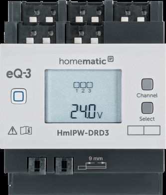
Geräteübersicht (s. Abbildung 1):
(A) Systemtaste (Anlerntaste und LED)
(B) Channel-Taste
14Funktion und Geräteübersicht
(C) Select-Taste
(D) LC-Display
(E) Busanschluss 1
(F) Busanschluss 2
(G) Anschlussklemmen für den Neutralleiter
(H) Anschlussklemmen für den Verbraucher/Last
(I) Anschlussklemmen für den Außenleiter
Displayübersicht (s. Abbildung 1):
Symbol Bedeutung
Kanal eingeschaltet
1 1
11 11
Kanal ausgeschaltet
RX 1 1
TXRX
RX V
Daten werden vom Bus empfangen
RX
TX
TX
TX V V
Daten werden zum Bus gesendet
Prozentangabe (eingeschaltet, wenn 0
oder 100 % angezeigt wird)
V Temperaturangabe (eingeschaltet, wenn
Temperatur angezeigt wird)
VV Spannungsangabe (eingeschaltet, wenn
Spannung angezeigt wird)
15Allgemeine Systeminformationen
4 Allgemeine Systeminformationen
Dieses Gerät ist Teil des Homematic IP Smart-Home-
Systems und kommuniziert über das Homematic IP Pro-
tokoll. Sie haben die Möglichkeit, alle Geräte des Systems
komfortabel und individuell über die Bedienoberfläche
der Zentrale CCU3 oder flexibel per Smartphone über
die Homematic IP App in Verbindung mit der Homema-
tic IP Cloud zu konfigurieren. Welcher Funktionsumfang
sich innerhalb des Systems im Zusammenspiel mit wei-
teren Komponenten ergibt, entnehmen Sie bitte dem
Homematic IP Wired Systemhandbuch. Alle technischen
Dokumente und Updates finden Sie stets aktuell unter
www.eQ-3.de.
5 Inbetriebnahme
5.1 Installationshinweise
Bevor Sie das Gerät installieren und in Betrieb
nehmen können, müssen Sie zunächst einen
Homematic IP Wired Access Point (HmIPW-
DRAP) in Betrieb nehmen.
Bitte notieren Sie sich vor der Installation die auf
dem Gerät angebrachte Gerätenummer (SGTIN)
und den Verwendungszweck, damit Sie das Gerät
im Nachhinein leichter zuordnen können. Alter-
nativ steht die Gerätenummer auch auf dem bei-
liegenden QR-Code-Aufkleber.
16Inbetriebnahme
Hinweis! Installation nur durch Personen mit
einschlägigen elektrotechnischen Kenntnissen
und Erfahrungen!*
Durch eine unsachgemäße Installation gefährden Sie
• Ihr eigenes Leben;
• das Leben der Nutzer der elektrischen Anlage.
Mit einer unsachgemäßen Installation riskieren Sie
schwere Sachschäden, z. B. durch Brand. Es droht für Sie
die persönliche Haftung bei Personen- und Sachschäden.
Wenden Sie sich an einen Elektroinstallateur!
*Erforderliche Fachkenntnisse für die Installation:
Für die Installation sind insbesondere folgende Fachkenntnisse er-
forderlich:
• Die anzuwendenden „5 Sicherheitsregeln“: Freischalten;
gegen Wiedereinschalten sichern; Spannungsfreiheit
feststellen; Erden und Kurzschließen; benachbarte, unter
Spannung stehende Teile abdecken oder abschranken;
• Auswahl des geeigneten Werkzeuges, der Messgeräte
und ggf. der persönlichen Schutzausrüstung;
• Auswertung der Messergebnisse;
• Auswahl des Elektro-Installationsmaterials zur Sicherstel-
lung der Abschaltbedingungen;
• IP-Schutzarten;
• Einbau des Elektroinstallationsmaterials;
• Art des Versorgungsnetzes (TN-System, IT-System,
TT-System) und die daraus folgenden Anschlussbedin-
gungen (klassische Nullung, Schutzerdung, erforderliche
Zusatzmaßnahmen etc.).
17Inbetriebnahme
Beachten Sie bei der Installation die Gefahrenhin-
weise gemäß „2 Gefahrenhinweise“ auf Seite 3.
Beachten Sie die auf dem Gerät angegebene Ab-
isolierlänge der anzuschließenden Leiter.
Zugelassene Leitungsquerschnitte zum Anschluss an den
Dimmaktor sind:
Starre Leitung [mm2] Flexible Leitung ohne
Aderendhülse [mm2]
0,75-2,50 0,75-2,50
5.2 Auswahl der Spannungsversorgung
Die Spannungsversorgung des Dimmaktors erfolgt über
zwei Wege. Der Logik-/Kommunikationsteil des Dimmak-
tors wird über den Homematic IP Wired Bus versorgt. Der
Bus wird wiederum vom Homematic IP Wired Access Point
(HmIPW-DRAP) gespeist (s. Bedienungsanleitung vom
HmIPW-DRAP).
Die einzelnen Dimmerkanäle versorgen sich über die ange-
schlossene Phase und sind völlig unabhängig voneinander.
Jeder Kanal kann dadurch einer anderen Phase und auch
unterschiedlichen FI-Bereichen zugeordnet werden (s. „5.3
Montage und Installation“ auf Seite 19).
Die Gesamtstromaufnahme über den Homematic IP Wi-
red Bus liegt bei etwa 3 mA.
18Inbetriebnahme
5.3 Montage und Installation
Bitte lesen Sie diesen Abschnitt erst vollständig,
bevor Sie mit der Installation beginnen.
Der Stromkreis, an dem das Gerät und die Last
angeschlossen wird, muss mit einem Leitungs-
schutzschalter gemäß EN60898-1 (Auslösecha-
rakteristik B oder C, max. 16 A Nennstrom, min. 6
kA Abschaltvermögen, Energiebegrenzungsklas-
se 3) abgesichert sein.
Für die Installation des Dimmaktors auf einer Hutschiene
in einem Stromkreisverteiler gehen Sie wie folgt vor:
• Schalten Sie den Stromkreisverteiler frei und de-
cken ggf. spannungsführende Teile ab (Sicher-
heitsregeln beachten).
• Entfernen Sie die Abdeckung des Stromkreisver-
teilers.
• Setzen Sie den Dimmaktor auf die Hutschiene
auf (s. Abbildung 2). Achten Sie darauf, dass die
Schrift auf dem Gerät und im Display für Sie les-
bar ist und die Anschlussklemmen der Kanäle 1
bis 3 oben liegen.
• Achten Sie dabei darauf, dass die Rastfeder kom-
plett einrastet und das Gerät fest auf der Schiene
sitzt.
• Verdrahten Sie das Gerät gemäß der Anschluss-
19Inbetriebnahme
zeichnung in Abbildung 3.
• Schließen Sie den Außenleiter an die Klemme (I),
die gedimmte Phase (zum Verbraucher) an die
Klemme (H) sowie den Neutralleiter an die ent-
sprechenden Klemmen (G) an (s. Abbildung 3).
Die Anschlüsse des Neutralleiters (G) sind gerätein-
tern nicht miteinander verbunden. Daher müssen
alle drei Klemmen (1N, 2N, 3N) an den Neutralleiter
angeschlossen werden. Falls die drei Lampen-
stromkreise über separate Fehlerstrom-Schutz-
schalter abgesichert werden, müssen auch jeweils
getrennte Neutralleiter angeschlossen werden.
Der Anschluss für den Außenleiter ist mit einem
Pfeil in Richtung der Klemme gekennzeichnet.
Die Anschlussklemme für die gedimmte Phase ist
mit einem Pfeil gekennzeichnet, der von der
Klemme weg zeigt. Zum Anschließen und auch
zum Lösen der Leiter ist der weiße Betätigungs-
drücker oben auf den Klemmen zu drücken.
Die Netzklemmen dürfen nur zum Anschluss der
Netzspannung an das Gerät bzw. zum Anschluss
von Verbrauchern an das Gerät verwendet wer
den. Das Weiterverbinden (Durchschleifen) von
Leitern über die Netzklemmen des Gerätes zu
anderen Geräten ist nicht erlaubt!
20Inbetriebnahme
• Verbinden Sie den Bus mit dem beiliegenden Ver-
bindungskabel (s. Abbildung 4).
Aus Gründen der elektrischen Sicherheit darf zum
Anschluss des Homematic IP Wired Bus aus-
schließlich das mitgelieferte Homematic IP Wired
Buskabel oder ein als Zubehör erhältliches eQ-3
Homematic IP Wired Buskabel anderer Länge
verwendet werden.
Die Busanschlüsse (E) und (F) sind parallel ge-
schaltet. Somit kann das kommende bzw. gehen-
de Buskabel an einen beliebigen der beiden An-
schlüsse angeschlossen werden.
• Setzen Sie den mitgelieferten Bus-Blindstopfen
ein, wenn Busanschluss 1 (E) oder Busanschluss
2 (F) nicht benötigt werden.
• Setzen Sie die Abdeckung des Stromkreisvertei-
lers wieder auf.
• Schalten Sie die Haussicherung wieder ein, um
den Anlernmodus des Geräts zu aktivieren (s. „5.4
Anlernen“ auf Seite 22).
Nach der Installation und vor dem Anlernen des Ge-
räts an die App, stehen Ihnen bereits einfache Be-
dienfunktionen (ggf. für Testzwecke) direkt am Ge-
rät zur Verfügung („6 Bedienung“ auf Seite 27).
21Inbetriebnahme
Die kleinste anwählbare Dimmstufe muss so ein-
gestellt sein, dass das angeschlossene Leucht-
mittel in dieser Betriebsart noch sichtbar leuchtet.
Diese kleinste Dimmstufe ist auf einen Wert von
5% (Referenzwert für eine 25-W-Glühlampe).
voreingestellt. Sollten Sie Glühlampen mit ande-
ren Leistungen oder keine Glühlampen (sondern
z. B. LED-Lampen) verwenden, kann es notwen-
dig sein, den Parameter entsprechend zu ändern.
Eine genaue Beschreibung zur Einstellung finden
Sie im HmIP-Wired Systemhandbuch oder im
WebUI Handbuch.
5.4 Anlernen
Bitte lesen Sie diesen Abschnitt erst vollständig,
bevor Sie mit dem Anlernen beginnen.
Richten Sie zunächst Ihren Homematic IP Wired
Access Point ein, um weitere Homematic IP Wi-
red Geräte im System nutzen zu können. Aus-
führliche Informationen dazu finden Sie in der
Bedienungsanleitung des Wired Access Points.
Damit der Dimmaktor in Ihr System integriert werden und
mit anderen Homematic IP Wired Geräten kommunizieren
kann, muss er zunächst angelernt werden.
Sie haben die Möglichkeit, den Dimmaktor für eine lokale
Konfiguration per PC an die Zentrale CCU3 anzulernen.
22Inbetriebnahme
Alternativ können Sie das Gerät für eine flexible Steuerung
per Smartphone-App an die Homematic IP Cloud an-
lernen. Dabei ist es möglich, das Wired System
• per Smartphone-App über den Homematic IP
Wired Access Point (HmIPW-DRAP) zu steuern
oder
• mit Homematic IP Funk-Komponenten über den
Homematic IP Access Point (HmIP-HAP) zu kom-
binieren.
5.4.1 Anlernen an die Zentrale CCU3
Nach dem Einbinden in die WebUI können Sie Ihr Home-
matic IP Wired Gerät softwarebasiert und komfortabel
steuern und konfigurieren sowie in Zentralenprogram-
men nutzen. Um den Dimmaktor an die Zentrale CCU3
anzulernen, gehen Sie wie folgt vor:
• Richten Sie zunächst Ihre Zentrale CCU3 gemäß
der zugehörigen Bedienungsanleitung ein und ler-
nen Sie den Homematic IP Wired Access Point an.
• Starten Sie die Benutzeroberfläche „Homematic
WebUI“ auf Ihrem PC.
• Klicken Sie auf den Button „Geräte anlernen“ im
rechten oberen Bereich des Browserfensters.
23Inbetriebnahme
• Um den Anlernmodus zu aktivieren, klicken Sie
im nächsten Fenster auf „HmIP Gerät anlernen“.
Die Zentrale wird für 60 Sekunden in den Anlern-
modus versetzt. Ein Infofeld zeigt die aktuell noch
verbleibende Anlernzeit.
24Inbetriebnahme
• Nach dem Anschluss an die Busleitung ist der An-
lernmodus des Dimmaktors für 3 Minuten aktiv.
Sind die 3 Minuten noch nicht verstrichen, wird
das Gerät automatisch angelernt.
Sie können den Anlernmodus manuell für weitere
3 Minuten starten, indem Sie die Systemtaste (A)
kurz drücken (s. Abbildung 5).
• Nach kurzer Zeit erscheint das neu angelernte
Gerät im Posteingang Ihrer Softwareoberfläche.
Neu angelernte Geräte und die zugehörigen Kanäle ste-
hen erst dann für Bedien- und Konfigurationsaufgaben
zur Verfügung, nachdem sie im Posteingang konfiguriert
wurden. Weitere Informationen finden Sie im Homema-
tic IP Wired Systemhandbuch unter www.eQ-3.de.
Im Betrieb ohne aktiven Internetzugang wählen
Sie die Option „Homematic IP Gerät ohne Inter-
netzugang anlernen“. Geben Sie zum Anlernen
die SGTIN und den Key des Geräts in die entspre-
chenden Felder ein. Die SGTIN und den Key fin-
den Sie auf dem beiliegenden Sticker. Bitte be-
wahren Sie den Sticker sorgfältig auf.
25Inbetriebnahme
5.4.2 Anlernen an die Homematic IP Cloud per Wired
Access Point
Wenn Sie Ihre Homematic IP Wired Geräte flexibel per
Smartphone-App steuern möchten, können Sie die
Homematic IP Wired Geräte einfach an die Homematic IP
Cloud anlernen. Gehen Sie dazu wie folgt vor:
• Öffnen Sie die Homematic IP App auf Ihrem
Smartphone.
• Lernen Sie den Homematic IP Wired Access Point
gemäß der zugehörigen Bedienungsanleitung
über die Smartphone-App an die Homematic IP
Cloud an.
• Wählen Sie den Menüpunkt „Gerät anlernen“ aus.
• Nach dem Anschluss an die Busleitung ist der An-
lernmodus des Dimmaktors für 3 Minuten aktiv.
Sie können den Anlernmodus manuell für weitere
3 Minuten starten, indem Sie die Systemtaste (A)
kurz drücken (s. Abbildung 5).
• Das Gerät erscheint automatisch in der Home-
matic IP App.
• Zur Bestätigung geben Sie in der App die letzten
vier Ziffern der Gerätenummer (SGTIN) ein oder
scannen Sie den QR-Code. Die Gerätenummer
finden Sie auf dem Aufkleber im Lieferumfang
oder direkt am Gerät.
• Warten Sie, bis der Anlernvorgang abgeschlossen ist.
26Bedienung
• Zur Bestätigung eines erfolgreichen Anlernvor-
gangs leuchtet die LED (A) grün. Das Gerät ist nun
einsatzbereit.
• Leuchtet die LED rot, versuchen Sie es erneut.
• Wählen Sie die gewünschte Lösung für Ihr Gerät
aus.
• Vergeben Sie in der App einen Namen für das Ge-
rät und ordnen Sie es einem Raum zu.
Wenn Sie bereits Homematic IP Geräte im Smart-
Home-System nutzen oder Ihre Wired Geräte mit
Funk-Komponenten von Homematic IP kombi-
nieren möchten, können Sie die Homematic IP
Wired Geräte auch einfach an einen (bestehenden)
Homematic IP Access Point anlernen. Lernen Sie
dazu den Homematic IP Wired Access Point
gemäß der zugehörigen Bedienungsanleitung an
den (bestehenden) Homematic IP Access Point
an. Anschließend gehen Sie wie oben beschrieben
vor, um den Dimmaktor anzulernen.
6 Bedienung
Über die folgenden Tasten stehen Ihnen einfache Bedien-
funktionen direkt am Gerät zur Verfügung:
• Systemtaste (A)
• Channel-Taste (B)
• Select-Taste (C)
27Bedienung
Systemtaste
Durch kurzes Drücken der Systemtaste (s. Abbildung 5)
können Sie die LCD-Hintergrundbeleuchtung bei allen an
den Bus angeschlossenen Geräten aktivieren.
Channel-Taste
Durch kurzes Drücken der Channel-Taste (s. Abbildung 6)
können Sie den gewünschten Kanal auswählen. Bei jeder
Betätigung wird ein Kanal weitergeschaltet.
Der ausgewählte Kanal wird durch Blinken des Symbols
gekennzeichnet. Der aktuelle Zustand des ausgewählten
Kanals (0 bis 100 %) wird im LC-Display angezeigt.
Select-Taste
Wenn Sie über die Channel-Taste einen Kanal ausgewählt
haben (s. Channel-Taste), können Sie durch kurzes Drü-
cken der Select-Taste (s. Abbildung 7) den Zustand des
Kanals (z. B. 0 oder 100 %) auswählen. Bei jeder Betäti-
gung wird ein Zustand weitergeschaltet.
Wenn Sie zuvor keinen Kanal ausgewählt haben, können
Sie durch kurzes Drücken der Select-Taste die folgenden
Anzeigen im LC-Display auswählen:
• Bus-Versorgungsspannung (in V)
• Temperatur im Dimmaktor (in °C)
• Leere Anzeige
Das Dimmen des eingestellten Kanals ist über die
Select-Taste nicht möglich.
28Fehlercodes und Blinkfolgen
7 Fehlercodes und Blinkfolgen
Blinkcode/ Bedeutung Lösung
LCD-Anzeige
Kurzes oranges Anlernmodus Geben Sie die
Blinken (alle aktiv letzten vier Ziffern
10 s) der Geräte-
Seriennummer zur
Bestätigung ein (s.
„5.4 Anlernen“ auf
Seite 22).
6x langes rotes Gerät defekt Achten Sie auf die
Blinken Anzeige in Ihrer
App oder wenden
Sie sich an Ihren
Fachhändler.
1x oranges Testanzeige Nachdem die
und 1x grünes Testanzeige
Leuchten erloschen ist,
können Sie
fortfahren.
E10 Temperatur zu Reduzieren Sie die
hoch angeschlossene Last
und lassen Sie das
Gerät abkühlen.
29Fehlercodes und Blinkfolgen
E11 Unterspan- Kontrollieren Sie
nung die Spannungs-
(Busspannung versorgung und
zu niedrig) dimensionieren Sie
die Spannungsver-
sorgung passend zur
Anzahl angeschlos-
sener Geräte.
E12* Kanal über- Beachten Sie die
lastet maximale Schaltleis-
tung und reduzie-
ren Sie die an den
betroffenen Kanal
angeschlossene Last
entsprechend.
E13* Kommuni- Kontrollieren Sie die
kation mit Spannungsversor-
Dimmerkanal gung des betroffe-
gestört nen Kanals
30Wiederherstellung der Werkseinstellungen
E17* Firmware- Starten Sie den
Update für Dimmaktor neu, um
Dimmer- die Übertragung des
kanal steht zur Updates zu starten.
Übertragung Ohne Update kann
an der Kanal nicht
weiter verwendet
werden.
*Diese Fehlercodes sind kanalbezogen. Sie werden immer im Wech-
sel mit der betroffenen Kanalnummer angezeigt. Die Kanalnummer
wird mit einem vorangestellten C dargestellt (C1 bis C3).
8 Wiederherstellung der
Werkseinstellungen
Die Werkseinstellungen des Geräts können wie-
derhergestellt werden. Dabei gehen alle Einstel-
lungen verloren.
Um die Werkseinstellungen des Dimmaktors wiederher-
zustellen, gehen Sie wie folgt vor:
• Drücken Sie für 4 s auf die Systemtaste (A), bis
die LED (A) schnell orange zu blinken beginnt (s.
Abbildung 5).
• Lassen Sie die Systemtaste wieder los.
• Drücken Sie die Systemtaste erneut für 4 s, bis die
LED grün aufleuchtet.
31Wartung und Reinigung
• Lassen Sie die Systemtaste wieder los, um das
Wiederherstellen der Werkseinstellungen abzu-
schließen.
Das Gerät führt einen Neustart durch.
9 Wartung und Reinigung
Das Gerät ist wartungsfrei. Überlassen Sie eine
Wartung oder Reparatur einer Fachkraft.
Schalten Sie vor Ausbau des Geräts unbedingt die
Netzspannung frei (Sicherungsautomat abschal-
ten)! Arbeiten am 230 V-Netz dürfen nur von ei-
ner Elektro-Fachkraft (nach VDE 0100) erfolgen.
Reinigen Sie das Gerät mit einem weichen, sauberen,
trockenen und fusselfreien Tuch. Verwenden Sie keine
lösemittelhaltigen Reinigungsmittel, das Kunststoffge-
häuse und die Beschriftung können dadurch angegriffen
werden.
10 Technische Daten
Geräte-Kurzbezeichnung: HmIPW-DRD3
Versorgungsspannung: 24 VDC, ±5 %, SELV
Stromaufnahme: 10 mA max. / 3 mA typ.
Leistungsaufnahme
Ruhebetrieb: 72 mW
32Technische Daten
Kanäle 1 bis 3
Versorgungsspannung 230 V~/50 Hz
Stromaufnahme: 0,88 A
Minimallast: 3 VA
Maximale Schaltleistung: 200 VA
Leistungsaufnahme im
Ruhebetrieb: 0,4 W
Dimmverfahren: Phasenabschnitt
Kontaktart: Halbleiterschaltelement,
ɛ-Kontakt
Verlustleistung des Geräts
für Wärmeberechnung: max. 6,5 W
Leitungsart und -querschnitt: starre und flexible Leitung,
0,75-2,5 mm²
Installation: auf Tragschiene (Hut-
schiene, DIN-Rail) gemäß
EN 60715
Schutzart: IP20
Umgebungstemperatur: -5 bis +40 °C
Abmessungen (B x H x T): 72 x 90 x 69 mm (4 TE)
Gewicht: 196 g
33Technische Daten
Lastart Kanal 1-3
Glühlampenlast 200 W
Lampen mit internem Vorschaltgerät
100 W
(LED/Kompaktleuchtstofflampe)
HV-Halogenlampen 200 W
Elektronische Transformatoren für
200 W
NV-Halogenlampen
Technische Änderungen vorbehalten.
Entsorgungshinweis
Gerät nicht im Hausmüll entsorgen! Elektroni-
sche Geräte sind entsprechend der Richtlinie
über Elektro- und Elektronik-Altgeräte über die
örtlichen Sammelstellen für Elektronik-Altgeräte
zu entsorgen.
Konformitätshinweis
Das CE-Zeichen ist ein Freiverkehrszeichen, das
sich ausschließlich an die Behörden wendet und
keine Zusicherung von Eigenschaften beinhaltet.
Bei technischen Fragen zum Gerät wenden Sie
sich bitte an Ihren Fachhändler.
34
Package contents
Quantity Description

1            Homematic IP Wired Dimming Actuator –
             3 channels
1            Bus connection cable
1            Bus blind plug
1            Operating manual

Documentation © 2018 eQ-3 AG, Germany.
All rights reserved. Translation from the original version in Ger-
man. This manual may not be reproduced in any format, either in
whole or in part, nor may it be duplicated or edited by electronic,
mechanical or chemical means, without the written consent of
the publisher.
Typographical and printing errors cannot be excluded. However,
the information contained in this manual is reviewed on a regular
basis and any necessary corrections will be implemented in the
next edition. We accept no liability for technical or typographical
errors or the consequences thereof.
All trademarks and industrial property rights are acknowledged.
Printed in Hong Kong
Changes may be made without prior notice as a result of techni-
cal advances.

152636 (web)
Version 1.4 (06/2021)
                                                                  35
Table of contents
1    Information about this manual....................................37
2    Hazard information.........................................................37
3    Function and device overview.....................................42
4    General system information........................................ 44
5    Start-up.............................................................................45
     5.1    Installation instructions...................................................... 45
     5.2    Selecting the power supply................................................47
     5.3    Mounting and installation.................................................. 48
     5.4    Teaching-in............................................................................51
            5.4.1 Teaching-in to the Central Control Unit
                    CCU3......................................................................... 52
            5.4.2 Teaching-in the Homematic IP cloud via
                    Wired Access Point................................................. 54
6    Operation..........................................................................56
7    Error codes and flashing sequences...........................58
8    Restore factory settings.................................................59
9    Maintenance and cleaning........................................... 60
10   Technical specifications.................................................61

36
Information about this manual
1 Information about this manual
Please read this manual carefully before beginning op-
eration with your Homematic IP Wired component. Keep
the manual so you can refer to it at a later date if you
need to.
If you hand over the device to other persons for use,
please hand over this manual as well.
Symbols used:
Attention!
This indicates a hazard.
Please note: This section contains important ad-
ditional information.
2 Hazard information
We do not assume any liability for damage to pro-
perty or personal injury caused by improper use
or the failure to observe the safety instructions. In
such cases, any claim under warranty will be in-
validated. We assume no liability for consequenti-
al damages.
Only qualified technicians are permitted to mount
and connect electrical devices.
37Hazard information
There is a potential risk of serious injury, fire or
property damage. Read and observe the instruc-
tions in full.
Electric shock hazard. Disconnect the mains vol-
tage and trip the miniature circuit breaker before
working on the device or replacing the lamps.
Electric shock hazard. The device has not been
designed to support safety disconnection. Even
when the output is switched off, the load is still
not electrically isolated from the mains.
For safety and licensing reasons (CE), it is not per-
mitted to make unauthorised changes and/or
modifications to the product.
Do not open the device. It does not contain any
parts that can be maintained by the user. There is
a risk of electric shock if the device is opened. In
the event of an error, please have the device che-
cked by an expert.
Do not use the device if there are signs of dama-
ge to the housing, control elements or connec-
ting sockets, for example, or if it demonstrates a
malfunction. If you have any doubts, have the
device checked by an expert.
38Hazard information
The device may only be operated in dry and dust-
free environments and must be protected from
the effects of moisture, vibrations, continuous
solar radiation and other methods of heat radiati-
on, cold and mechanical loads.
The device is not a toy; do not allow children to
play with it. Do not leave packaging material lying
around: items such as plastic films/bags and pie-
ces of polystyrene can be dangerous in the hands
of a child.
When connecting to the device terminals, be sure
to take the permissible cables and cable cross
sections into account.
The actuator is part of the building installation.
The relevant national standards and directives
must be taken into consideration during planning
and set-up. The device has been designed solely
for operation on a 230 V / 50 Hz AC supply. Only
qualified electricians (to VDE 0100) are permitted
to carry out work on the 230 V mains. Applicable
accident prevention regulations must be com-
plied with whilst such work is being carried out.
To avoid electric shocks from the device, please
disconnect the mains voltage (trip the miniature
circuit breaker). Non-compliance with the
39Hazard information
installation instructions can cause fire or introdu-
ce other hazards.
For secure operation, the device has to be ins-
talled in a power distribution panel according to
VDE 0603, DIN 43871 (low-voltage sub-distribu-
tion board), DIN 18015-x. The installation must
take place on a mounting rail (DIN rail) according
to EN 60715. Installation and wiring have to be
performed according to VDE 0100 (including
VDE 0100-410, VDE 0100-510, etc.). Please con-
sider the technical connection requirements
(TAB) of your energy supplier.
The connected consumers require sufficient in-
sulation.
Exceeding this capacity could lead to the de-
struction of the device, fires or electric shocks.
Please take the technical data – particularly the
maximum permissible switching capacity of the
load circuits and the type of consumer to be con-
nected – into account before connecting a con-
sumer. Do not exceed the capacity specified for
the device.
40Hazard information
The dimming actuator is only suitable for light
bulbs and high-voltage and low-voltage halogen
lamps with electronic transformers as well as dim-
mable LED lamps.
Please only connect ohmic and capacitive lamp
R,C loads to the dimming actuator. Devices such as
televisions, computers and motors are not suita-
ble.
Do not connect any LEDs or compact fluorescent
lamps that are not specifically designed for dim-
ming. This may damage the device.
SELV/PELV power circuits must not be connected
to the load terminals.
Do not connect lamps with integrated dimmers.
This may damage the device.
In the case of operation with electronic ballasts,
only use transformers that meet the requirements
of EN 61347-1 and EN 61047.
The device can detect ripple control signals to avo-
id brightness fluctuations. Nevertheless, the light
sources may still flicker briefly due to ripple control
signals as these cannot be ruled out entirely.
41Function and device overview
The device is only suitable for use in living areas,
business and trade areas, and small-scale com-
panies.
If the device/system is used in security applica-
tions, it has to be operated in connection with a
UPS (uninterruptible power supply) in order to
bridge possible power failures.
Using the device for any purpose other than that
described in this operating manual does not fall
within the scope of intended use and shall invali-
date any warranty or liability.
3 Function and device overview
The Homematic IP Wired Dimming Actuator 3-channel
is easy to install on a DIN rail in a power distribution pa-
nel. Once installed, the device dims or switches connec-
ted consumers (lights) on and off via three independent
channels.
In the Homematic IP Wired System, the dimming actuator
can switch and dim lamps or other lighting systems with
ease via taught-in pushbuttons, remote control or the
free Homematic IP smartphone app.
42Function and device overview
The dimming actuator enables dimming of
• normal incandescent lamps
• high-voltage halogen lamps
• low-voltage halogen lamps with electronic trans-
formers
• dimmable energy-saving lamps*1
• dimmable LED lamps*2
*1 The usable dimming range is usually extremely restricted.
*2 It is not guaranteed that the dimming behaviour will function
correctly with all types of LED lamps.
Device overview (see Figure 1):
(A) System button (teach-in button and LED)
(B) Channel button
(C) Select button
(D) LCD
(E) Bus connection 1
(F) Bus connection 2
(G) Connecting terminals for the neutral conductor
(H) Connecting terminals for the consumer/load
(I) Connecting terminals for the phase conductor
43General system information
Display overview (see Figure 1):
Symbol Meaning
Channel switched on
1 1
11 11
Channel switched off
RX 1 1
TXRX
RX V
Data received from bus
RX
TX
TX
TX V V
Data sent from bus
Percentage display (switched on when 0
or 100% is displayed)
V Temperature display (switched on when
the temperature is displayed)
VV Voltage display (switched on when the
voltage is displayed)
4 General system information
This device is part of the Homematic IP smart home
system and works with the Homematic IP protocol. All
devices of the system can be configured comfortably
and individually with the user interface of the Central
Control Unit CCU3 or flexibly via the Homematic IP
smartphone app in connection with the Homematic IP
44Start-up
cloud. All available functions provided by the system in
combination with other components are described in
the Homematic IP Wired Installation Guide. All current
technical documents and updates are provided at
www.eQ-3.com.
5 Start-up
5.1 Installation instructions
Before you can install the device and put it into
operation, you must first put a Homematic IP Wi-
red Access Point (HmIPW-DRAP) into operation.
Before installation, please note the device num-
ber (SGTIN) labelled on the device as well as the
intended use in order to make later allocation ea-
sier. You can also find the device number on the
QR code sticker supplied.
Please note! Only to be installed by persons with
the relevant electro-technical knowledge and
experience.*
Incorrect installation can put
• your own life at risk;
• and the lives of other users of the electrical system.
Incorrect installation also means that you are running the
45Start-up
risk of serious damage to property, e.g. because of a fire.
You may be personally liable in the event of injuries or
damage to property.
Contact an electrical installer!
*Specialist knowledge required for installation:
The following specialist knowledge is particularly important during
installation:
• The “5 safety rules” to be used:
Disconnect from mains; Safeguard from switching on
again; Check that system is de-energised; Earth and
short circuit; Cover or cordon off neighbouring live parts;
• Select suitable tool, measuring equipment and, if neces-
sary, personal safety equipment;
• Evaluation of measuring results;
• Selection of electrical installation material for safeguard-
ing shut-off conditions;
• IP protection types;
• Installation of electrical installation material;
• Type of supply network (TN system, IT system, TT sys-
tem) and the resulting connecting conditions (classical
zero balancing, protective earthing, required additional
measures etc.).
Please observe the hazard information in section
„2 Hazard information“ on page 37 during in-
stallation.
Please observe the cable stripping lengths for the
cables to be connected as specified on the device.
46Start-up
Permitted cable cross sections for connecting to the
dimming actuator are:
Rigid cable [mm2] Flexible cable without
ferrule [mm2]
0.75-2.50 0.75-2.50
5.2 Selecting the power supply
There are two types of power supply for the dimming ac-
tuator. The logic/communication component of the dim-
ming actuator is supplied via the Homematic IP Wired Bus.
In turn, the bus is supplied by the Homematic IP Wired Ac-
cess Point (HmIPW-DRAP) (refer to the operating manual
for the HmIPW-DRAP).
The individual dimmer channels are supplied via the con-
nected phase and are completely independent of each
other. This allows each channel to be assigned to a dif-
ferent phase, as well as to different RCD areas (see „5.3
Mounting and installation“ on page 48).
The total current consumption via the Homematic IP Wired
Bus is around 3 mA.
47Start-up
5.3 Mounting and installation
Please read this entire section before starting to
install the device.
The circuit to the which the device and the load
will be connected has to be secured by a cable
protection switch in accordance with EN 60898-
1 (tripping characteristic B or C, max. 16 A rated
current, min. 6 kA interrupting rating, energy limi-
ting class 3).
To install the dimming actuator on a DIN rail in a power
distribution panel, please proceed as follows:
• Disconnect the power distribution panel from the
mains and cover any live parts (see safety rules).
• Remove the cover from the power distribution
panel.
• Place the dimming actuator onto the DIN rail (see
Figure 2). Ensure that you can read the writing on
the device and on the display and that the con-
necting terminals for channels 1 to 3 are at the
top.
• Make sure that the locating springs engage pro-
perly and that the device is securely seated on
the rail.
• Wire the device according to the wiring diagram
in Figure 3.
• Connect the phase conductor to the terminal (I),
48Start-up
the dimmed phase (to the consumer) to the ter-
minal (H), and the neutral conductor to the cor-
responding terminals (G) (see Figure 3).
The connections for the neutral conductor (G) are
not connected to each other inside the device. For
this reason, all three terminals (1N, 2N, 3N) must be
connected to the neutral conductor. If the three
lamp circuits are protected by separate residual-
current devices, a separate neutral conductor must
also be connected for each one.
The connection for the phase conductor is
marked with an arrow pointing towards the ter-
minal. The connecting terminal for the dimmed
phase is marked with an arrow pointing away
from the terminal. The white actuator button on
top of the terminals must be pressed to connect
and also to release the conductor.
The supply terminals may only be used to con-
nect the mains voltage to the device or to con-
nect consumers to the device. It is not permitted
to interconnect (loop) conductors to other de-
vices via the device supply terminals.
• Connect the bus using the supplied connection
cable (see Figure 4).
49Start-up
For reasons of electrical safety, only the supplied
Homematic IP Wired Bus cable or an eQ-3
Homematic IP Wired Bus cable accessory of ano-
ther length may be used to connect the Home-
matic IP Wired Bus.
The bus connections (E) and (F) are connected in
parallel. This allows the incoming and/or outgo-
ing bus cable to be connected to either of the
two connections.
• Attach the supplied bus blind plug if bus connec-
tion 1 (E) or bus connection 2 (F) is not required.
• Replace the cover of the power distribution pa-
nel.
• Switch the fuse of the power circuit on again to
activate the teach-in mode of the device (see
Section „5.4 Teaching-in“ on page 51).
Once the installation process is complete, a number
of basic operating functions (such as those for test
purposes) are available directly on the device before
the device has been taught-in to the app (see Sec-
tion „6 Operation“ on page 56).
The lowest selectable dimming level must be set
in such a way that the connected light source still
illuminates visibly in this operating mode. This
50Start-up
lowest dimming level is set to a value of 5% (refe-
rence value for a 25 W light bulb). If you use light
bulbs with other outputs or a different light source
entirely (such as LED lamps), it may be necessary
to change the parameters accordingly. For a de-
tailed description of the settings, refer to the HmIP
Wired system manual or the WebUI manual.
5.4 Teaching-in
Please read this entire section before starting
the teach-in procedure.
First set up your Homematic IP Wired Access
Point to enable operation of other Homematic IP
Wired devices within your system. For further in-
formation, please refer to the operating manual
for the Wired Access Points.
To integrate the dimming actuator into your system and
enable it to communicate with other Homematic IP Wi-
red devices, you must teach it in first.
The option is available to teach the dimming actuator for
a local configuration into the Central Control Unit CCU3
via PC.
Alternatively, you can teach the device into the Home-
matic IP cloud via the smartphone app to enable flexi-
ble controls. This makes it possible to control the Wired
System
51Start-up
• via the smartphone app using the Homematic IP
Wired Access Point (HmIPW-DRAP) or
• combine it with Homematic IP wireless compo-
nents via the Homematic IP Access Point (HmIP-
HAP).
5.4.1 Teaching-in to the Central Control Unit CCU3
After teaching-in the device to the WebUI, it can be con-
veniently controlled, configured and used in central con-
trol unit programs via the software interface. To teach-in
the dimming actuator to the Central Control Unit CCU3,
proceed as follows:
• First set up your Central Control Unit CCU3 ac-
cording to the accompanying operating manual
and teach-in the Homematic IP Wired Access
Point.
• Start the user interface “Homematic WebUI” on
your computer.
• Click the “Teach-in devices” button on the right-
hand side of the screen.
• To activate teach-in mode, click “Teach-in HmIP
52Start-up
device” in the next window. The teach-in mode
of the Central Control Unit will be activated for
60 seconds. An information box shows how
much teach-in time remains.
• After connecting to the bus cable, the dimming
actuator teach-in mode remains activated for 3
minutes. The device is taught-in automatically as
long as the three minutes do not elapse.
You can manually start the teach-in mode for
another 3 minutes by pressing the system button
(A) briefly (see Figure 5).
53Start-up
• After a short time, the newly taught-in device ap-
pears in the inbox of your software interface.
Newly taught-in devices and the corresponding channels
are ready for operation and configuration in the system
only after they have been configured in the inbox. Further
information is available in the Homematic IP system ma-
nual, which is available for download at www.eQ-3.de.
For operation without an active Internet connec-
tion, please select the option “Teaching-in the
Homematic IP device without an Internet con-
nection”. Please enter the SGTIN and key of the
device into the corresponding fields. You will find
the SGTIN and the key on the supplied sticker.
Please keep the sticker in safe place.
5.4.2 Teaching-in the Homematic IP cloud via Wired
Access Point
If you would like to control your Homematic IP Wired
devices flexibly via the smartphone app, you can simply
teach-in the Homematic IP Wired devices to the Home-
matic IP cloud. To do this, please proceed as follows:
• Open the Homematic IP app on your smartpho-
ne.
• Teach-in the Homematic IP Wired Access Point
to the Homematic IP cloud via the smartphone
app according to the accompanying operating
54Start-up
manual.
• Select the menu item “Teach-in device”.
• After connecting to the bus cable, the dimming
actuator teach-in mode remains activated for 3
minutes.
You can manually start the teach-in mode for
another 3 minutes by pressing the system button
(A) briefly (see Figure 5).
• Your device will automatically appear in the
Homematic IP app.
• To confirm, please enter the last four digits of the
device number (SGTIN) in your app or scan the
QR code. The device number can be found on
the sticker supplied or attached to the device.
• Please wait until teach-in is completed.
• If teaching-in was successful, the LED (A) lights
up green. The device is now ready for use.
• If the LED lights up red, please try again.
• Select the desired solution for your device.
• In the app, give the device a name and allocate
it to a room.
If you already use Homematic IP devices in your
smart home system or would like to combine
your wired devices with wireless components
from Homematic IP, you can also simply teach-in
55Operation
the Homematic IP Wired devices to an (existing)
Homematic IP Access Point. All you have to do is
teach-in the Homematic IP Wired Access Point to
the (existing) Homematic IP Access Point
according to the accompanying operating
instructions. Finally, proceed as described above
to teach-in the dimming actuator.
6 Operation
Basic operating functions are available directly on the de-
vice via the following buttons:
• System button (A)
• Channel button (B)
• Select button (C)
System button
By briefly pressing the system button (see Figure 5) you
can activate the LCD background lighting on all devices
connected to the bus.
Channel button
By briefly pressing the channel button (see Figure 6) you
can select the desired channel. You can scroll through
the channels by pressing the button repeatedly.
The symbol flashes to highlight the selected channel. The
current state of the selected channel (0 to 100%) is dis-
played on the LCD.
56Operation
Select button
If you have already selected a channel using the channel
button (see Channel button), you can then briefly press
the select button (see Figure 7) to select the channel state
(for example, 0 or 100%). You can scroll through the sta-
tes by pressing the button repeatedly.
If you have not yet selected a channel, you can briefly
press the select button to select from the following dis-
plays on the LCD:
• Bus supply voltage (in V)
• Temperature in the dimming actuator (in °C)
• Empty display
It is not possible to dim the set channel using the
select button.
57Error codes and flashing sequences
7 Error codes and flashing
sequences
Flashing Meaning Solution
code/LCD
Short Teach-in mode Enter the last four num-
orange active bers of the device serial
flashing number to confirm (see
(every Section „5.4 Teaching-
10 s) in“ on page 51).
6x long Device defec- Please check the
red tive display in your app or
flashing contact your retailer.
1x orange Test display Once the test display
and 1x has stopped, you can
green light continue.
E10 Temperature Reduce the connected
too high load and let the device
cool down.
E11 Undervoltage Check the supply
(bus voltage too voltage and adjust it ac-
low) cording to the number
of connected devices.
58Restore factory settings
E12* Channel over- Observe the maximum
loaded switching capacity
and reduce the load
connected to the
channel accordingly.
E13* Communication Check the supply
with dimmer voltage of the affected
channel dis- channel.
rupted
E17* Firmware up- Restart the dimming
date for dimmer actuator to start trans-
channel ready mission of the update.
for transmission The channel cannot
continue to be used
without an update.
*These error codes are channel related. They are always displayed
alternately with the relevant channel number. The channel number
is displayed with a preceding letter C (C1 to C3).
8 Restore factory settings
The factory settings of the device can be resto-
red. If you do this, you will lose all your settings.
To restore the factory settings of the dimming actuator,
please proceed as follows:
59Maintenance and cleaning
• Press and hold down the system button (A) for 4
seconds until the LED (A) starts quickly flashing
orange (see Figure 5).
• Release the system button again.
• Press and hold down the system button again for
4 seconds until the status LED lights up green.
• Release the system button to finish the proce-
dure.
The device will perform a restart.
9 Maintenance and cleaning
The product does not require any maintenance.
Enlist the help of an expert to carry out any main-
tenance or repairs.
The mains voltage must be disconnected before
the device is removed (trip the miniature circuit
breaker). Only qualified electricians (to VDE 0100)
are permitted to carry out work on the 230 V
mains.
Clean the device using a soft, lint-free cloth that is clean
and dry. Do not use any detergents containing solvents,
as they could corrode the plastic housing and label.
60Technical specifications
10 Technical specifications
Device short description: HmIPW-DRD3
Supply voltage: 24 V DC, ±5%, SELV
Current consumption: 10 mA max. / 3 mA typ.
Power consumption in
standby: 72 mW
Channels 1 to 3
Supply voltage 230 V~ / 50 Hz
Current consumption: 0.88 A
Minimum load: 3 VA
Maximum switching capacity: 200 VA
Standby power consumption: 0.4 W
Dimming method: Reverse phase control
Contact type: Semiconductor switching
element, ɛ-contact
Device power loss for
heat calculation: Max. 6.5 W
Cable type and cross section: Rigid and flexible cable,
0.75–2.5 mm²
Installation: On mounting rail (DIN rail)
according to EN 60715
Degree of protection: IP20
Ambient temperature: -5 to +40°C
Dimensions (W x H x D): 72 x 90 x 69 mm (4 WM)
Weight: 196 g
61Technical specifications
Load type Channel 1-3
Light bulb load 200 W
Lamps with internal ballasts (LED /
100 W
compact fluorescent lamps)
HV halogen lamps 200 W
Electronic transformers for LV halogen
200 W
lamps
Subject to technical changes.
Instructions for disposal
Do not dispose of the device with regular domes-
tic waste! Electronic equipment must be dis-
posed of at local collection points for waste elec-
tronic equipment in compliance with the Waste
Electrical and Electronic Equipment Directive.
Information about conformity
The CE sign is a free trading sign addressed ex-
clusively to the authorities and does not include
any warranty of any properties.
For technical support, please contact your retailer.
62Sie können auch lesen