JCT ANALYSENTECHNIK GMBH 01/20
←
→
Transkription von Seiteninhalten
Wenn Ihr Browser die Seite nicht korrekt rendert, bitte, lesen Sie den Inhalt der Seite unten
01/20

JCT                      B EDIENUNGSANLEITUNG
A NALYSENTECHNIK G MBH   O PERATING M ANUAL

                             JES-370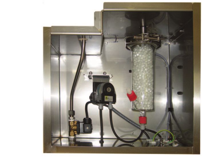
Manual JES-370

Inhalt                                                     Table of Content
1. Einleitung                                    3         1. Introduction                                      3
  1.1. Montage                                   3           1.1. Mounting                                      3
  1.2. Modular                                   3           1.2. Versatile                                     3
  1.3. Service und Sicherheit                    3           1.3. Service and security                          3
  1.4. Allgemeine Sicherheitsinformation         3           1.4. General safety information                    3
2. Beschreibung                                  4         2. Description                                       4
  2.1. Modell - Übersicht                        6           2.1. Model overview                                6
3. Bestellnummern                                7         3. Order codes                                       7
4. Technische Daten                              10        4. Technical data                                    10
  4.1. Druckverlauf                              11          4.1. Pressure characteristics                      11
  4.2. Gasfluss Diagramm                         11          4.2. Flow charts                                   11
5. Installation, Sichtkontrolle                  12        5. Installation, unpacking                           11
6. Installationsvorschriften                     12        6. Installation instructions                         12
  6.1. Montage                                   12          6.1. Mounting                                      12
  6.2. Kondensatabtransport (Option)             14          6.2. Condensate removal (option)                   14
  6.3. Kalibriergasanschluss (Option)            14          6.3. Calibration port (option)                     14
  6.4. Montage an vertikalem Kamin               15          6.4. Vertical duct installation                    15
  6.5. Montage an horizontalem Kamin             15          6.5. Horizontal duct installation                  15
  6.6. Montagepositionen                         16          6.6. Mounting positions                            16
  6.7. Montage In-situ Vorfilter                 16          6.7. Mounting of In-situ pre filter                16
  6.8. Elektrischer Anschluss                    17          6.8. Electrical connections                        17
  6.9. Anschluss von Federzugklemmen             18          6.9. Connection of spring type terminal            18
7. Temperaturregler Allgemein                    18        7. Temperature controller abstract                   18
8. Inbetriebnahme                                23        8. Start up                                          23
9. Wartung und Service                           24        9. Maintenance and service                           24
  9.1. Ersetzen des Filterelementes              24          9.1. Replacement of filter element                 24
  9.2. Ersetzen des ABS Glasabscheidefilters     25          9.2. Replacement of ABS glass separator filter     25
  9.3. Kondensatpumpe                            25          9.3. Condensate pump                               25
10. Fehlerdiagnose Checkliste                    28        10. Fault diagnostic check list                      28
11. Abmessungen                                  29        11. Dimensions                                       29

© 2020 JCT Analysentechnik GmbH                            © 2020 by JCT Analysentechnik GmbH
Reproduktion im Ganzen oder auszugsweise ohne vor-         Reproduction in whole or in part in any form or medium
herige schriftliche Genehmigung verboten.                  without written permission is prohibited
Alle verwendeten Markenzeichen sind Eigentum der ent-      All trademarks not explicitly mentioned are property of
sprechenden Rechteinhaber.                                 their legal owners.
JCT bietet diese Betriebsanleitung "wie vorliegend" ohne   JCT provides this operating manual "as is" without any
jede Garantie in irgendeiner Art, weder ausdrücklich       warranty of any kind, either express or implied, including
noch stillschweigend, einschließlich Garantien oder Be-    warranties or conditions of merchantability or fitness for
dingungen der Marktgängigkeit oder Eignung für einen       a particular purpose.
bestimmten Zweck.
Technische Änderungen vorbehalten.                         Subject to technical modifications without notice.

BA_DE_JES370_v1.4       –––––––––––––––––––––––––– [ 2 / 30 ] ––––––––––––––––––––––––––
Manual JES-370
1. Einleitung                                                1. Introduction
Die beheizte Gasentnahmesonde JES-370 dient zur              The heated gas sampling probe JES-370 is designed for
kontinuierlichen Entnahme von staub- und aerosol-hal-        continuous use in DENOX plants (SCR) even when the
tigen Gasen bei DENOX Anlagen (SCR). Wasserdampf             sample contains dust and aerosols. Water vapour and
und hohe korrosive Gasfeuchte müssen über dem Tau-           high corrosive gases must be kept above their dew point
punkt gehalten werden, damit keine Veränderung des           to prevent corrosion and sample degradation prior to the
Gases vor den Analysengeräten oder der Probenaufbe-          analysis or sample conditioning.
reitung stattfinden kann.
Die Gasentnahmesonde JES-370 ist in verschiedenen            The JES-370 can be delivered in several versions to
Versionen lieferbar. Dadurch können unterschiedliche         meet user specific requirements.
Anforderungen erfüllt werden.
Die JES-370 ist mit einem großflächigen, austauschba-        The JES-370 incorporates a non-corrosive heated, re-
ren beheizten Keramik-Filterelement ausgestattet. Das        placeable ceramic filter element. The filter element is
Filterelement ist in einem elektrisch beheizten Edelstahl-   mounted in an electrically heated stainless steel housing
gehäuse montiert und zusätzlich in einem thermisch iso-      covered by a thermal isolated weather protection enclo-
lierten Wetterschutzgehäuse untergebracht. Die               sure. The temperature regulation is done by a mainten-
Temperaturregelung erfolgt durch eine wartungsfreie          ance free, fully electronic temperature controller with
vollelektronische Regelung mit Alarmmeldung bei Unter-       under temperature alarm.The heated sample hose JH
temperatur. Die beheizte Messgasleitung der Serie JH         series is directly connected with a moveable PG42 cable
wird direkt am Gehäuse der Sonde über eine verschieb-        conduit on the probes housing. A universal mounting
bare PG42 Verschraubung montiert. Für die Montage für        clamp is available to connect other types of heated sam-
anderer Heizleitungstypen steht eine Montageschelle          ple hoses. For proper selection of various sample pipe
zur Verfügung. Für eine korrekte und optimale Auswahl        constructions and materials please refer to our trained
der verschiedenen Entnahmerohre und Materialien steht        staff.
Ihnen unser geschultes Personal gerne zur Seite.

1.1. Montage                                                 1.1. Mounting
Die Gasentnahmesonde besteht aus dem beheiztem Fil-          The complete unit consists of the heated filter head, tem-
terkopf, Temperaturregler, Montageflansch, ABS Glas-         perature controller, mounting flange, ABS glass separa-
abscheider,       Prozessabsperrkugelhahn           und      tor filter, process shut off valve and installation material.
Montagematerial. Die Sonde wird horizontal direkt an         Mounting should be done in a horizontal position. The
einem Standard-Prozessflansch montiert. Die JES-370          probe´s design fits for mounting directly to a standard
sollte zwischen 5° und 10° aus der Horizontalen fallend      flange. The JES-370 should be built in an angle between
eingebaut werden, damit anfallendes Kondensat zurück         5° and 10° from the horizontal falling, to allow conden-
in den Prozess abgeleitet werden kann.                       sate flow back into the process.

1.2. Modular                                                 1.2. Versatile
Unterschiedliche Entnahmerohrmaterialien, elektrisch         Different sample pipe materials, electrically heated sam-
beheizte Entnahmerohre, große Vorfilter und viele zu-        ple pipes, large pre filters and many upgrade options
sätzliche Optionen machen die JES-370 anpassungsfä-          make the JES-370 very flexible for different applications.
hig für verschiedenste Applikationen.

1.3. Service und Sicherheit                                  1.3. Service and security
Ein Statuskontakt signalisiert Störung und Untertempe-       A temperature status contact signalizes fault and under
ratur, eine Übertemperaturbegrenzung schützt vor Über-       temperature, an over temperature protection avoids
hitzung. Der Filterwechsel und der Austausch des ABS         overheating. Filter replacement and replacement of the
Glasabscheiders können ohne Werkzeug und ohne De-            ABS glas separator filter can be done easily without any
montage der beheizten Messgasleitung durchgeführt            tools and without disconnecting the heated sample line.
werden.

1.4. Allgemeine Sicherheitsinformation                       1.4. General safety information
Die Gasentnahmesonden sind hochentwickelte Geräte,           Gas sample probes are sophisticated devices intended
die nur von qualifiziertem Personal bedient werden dür-      for use by qualified personnel only. It is necessary that
fen. Es ist notwendig, dass dieses Handbuch von jenen,       this manual is been read and understood by those who
die diese Ausrüstung installieren, benutzen bzw. warten,     will install, use and maintain this equipment.
gelesen und verstanden wurde.

BA_DE_JES370_v1.4        –––––––––––––––––––––––––– [ 3 / 30 ] ––––––––––––––––––––––––––
Manual JES-370
HINWEIS NOTE
Liegt diesem Manual ein Appendix bei, gelten zusätzlich If an appendix is attached to this manual the information
und im Zweifelsfall vorrangig die Informationen des Ap- of the appendix applies additionally and has priority over
pendixes.. manual in case of doubt.
ACHTUNG CAUTION
Die Gasentnahmesonde JES-370 ist nicht für den Ein- The sample probe JES-370 is not suitable for use in ha-
satz in explosionsgefährdeten Bereichen geeignet. zardous areas.
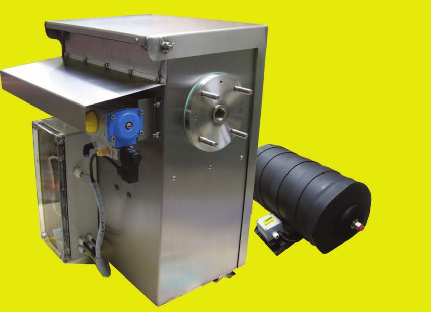
2. Beschreibung 2. Description
BA_DE_JES370_v1.4 –––––––––––––––––––––––––– [ 4 / 30 ] ––––––––––––––––––––––––––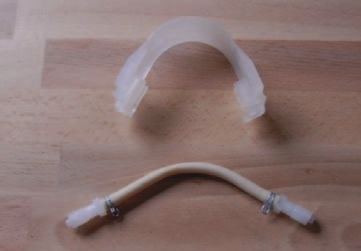
Manual JES-370

1        Flansch                                          1      Flange
2        Gehäusedichtung                                  2      Housing gasket
5        Mantel                                           5      Cylinder
6        Filterelementverschraubung                       6      Filter element screw
7        Filterelementdichtung                            7      Filter element gasket
8        Filterelement                                    8      Filter
9        Filterhalter Trägerelement                       9      Filter retainer
10       Filterhalter Dichtkolben                         10     Filter tighting piston
11       O-Ring B                                         11     O-ring B
12       O-Ring A                                         12     O-ring A
13       Abziehbolzen                                     13     Bolt
15       Schwenkarm                                       15     Pivoting frame
17       Abziehvorrichtung                                17     Extractor
21       T - Griff                                        21     T - handle
22       Alu Mantel                                       22     Aluminium cover
23       Ringheizkörper                                   23     Ring heater element
24       Temperaturfühler Pt 100                          24     Temperature sensor Pt 100
25       Wärme Isolation                                  25     Thermal isolation
26       Gehäuse                                          26     Housing
27       Erdungsanschluss                                 27     Ground connection pin
44       Temperaturregler                                 44     Temperature controller
45       Messgas Eingang                                  45     Sample gas inlet
46       Messgas Ausgang                                  46     Sample gas outlet
48       Kalibriergas Anschluss                           48     Calibration gas port (option)
49       Rückschlagventil                                 49     Non return valve
53       Dichtung für Entnahmerohr                        53     Gasket for sample tube
54       Flanschdichtung                                  54     Flange gasket
55       Puffertank                                       55     Air accumulator
70       Rückschlagventil                                 70     Non return valve
71       Ventil für Vorfilterrückspülung                  71     Valve for pre-filter back purge
72       Prozessabsperrkugelhahn                          72     Process shut off ball valve
73       Aktuator für Prozessabsperrkugelhahn             73     Actuator for process shut off ball valve
74       Magnetventil                                     74     Solenoid valve
75       Anschluss für Vorfilterrückspülung               75     Connection for pre-filter back purge
76       Puffertank beheizt                               76     Heated air accumulator
77       SPS für Rückspülung                              77     PLC for back purge
80       ABS-Filter Gehäuse                               80     ABS-filter housing
81       ABS-Filter Glaskugeln                            81     ABS-filter glas balls
82       ABS-Filter Schnellverschluss                     82     ABS-filter snap closing
83       ABS-Filter GL-Anschlussverschraubung             83     ABS-filter GL hose fitting
84       ABS-filter O-Ring                                84     ABS-filter O-ring
85       Kondensatschlauch                                85     Condensate tube
86       Kondensatpumpe                                   86     Condensate pump
87       Kondensatausgang                                 87     Condensate outlet
88       Temperaturfühler Pt 100                          88     Temperature sensor Pt 100
98       ABS-Filter Frostschutz                           98     ABS-Filter Frostschutz
99       ABS-Filter Heizung                               99     Heater for ABS filter
100      Thermoschalter für ABS-Filter Frostschutz        100    Thermo switch for ABS filter freeze protection

BA_DE_JES370_v1.4      –––––––––––––––––––––––––– [ 5 / 30 ] ––––––––––––––––––––––––––
Manual JES-370
2.1. Modell - Übersicht                                                                         2.1. Model overview

Basismodell beinhaltet                                                                                     Basic model includes
ABS Glasabscheidefilter                                                                                    ABS glass separator filter
Wetterschutzgehäuse                                                                                        Weather protection housing
Prozessabsperrkugelhahn                                                                                    Process shut offff ball valve
Temperaturregler 315°C (einstellbar)                                                                       Temperature controller ( 315°C (adju
                                                                                                                                             j stable)
Vorfilterrückspülung mit Absperr- & Rückschlagventil (nicht bei Option V0)                                 Pre- filter back purge with cutoffff valve & nrv valve (not in option V0)

Verfügbare Varianten                                                                                       Avvailable Features
Flansch                                                                                                    Flange
DN65/PN6                                                     Z1                                            DN65/PN6
2" ANSI                                                      Z2                                            2" ANSI
Filter Element                                                                                             Filter element
2 μm Keramik                                                      F1                                       2 μm ceramic
0,2 μm Keramik oberflächenbeschichtet                             F2                                       0,2 μm ceramic surface coated
Stromversorgung                                                                                            Power supply
230 VAC 50/60Hz                                                        X1                                  230 VAC 50/60Hz
115 VAC 50/60Hz                                                        X2                                  115 VAC 50/60Hz
Prozessabsperrkugelhahn                                                                                    Process shut offff ball valve

Ohne Absperrkugelhahn und ohne Vorfilterrückspülung                          V0                            without shut offff ball valve and without pre-filter back purge
mit manueller Betätigung                                                     V1                            with manual operation
mit pneumatischem Aktuator                                                   V2                            with pneumatic actuator
mit pneumatischem Aktuator und Pilottvventil                                 V3                            with pneumatic actuator and pilot valve
mit elektrischem Aktuator 230 VAC                                            V4                            with electric actuator 230 VAC
ABS Heizung                                                                                                ABS heater
ohne ABS Heizung, mit Kondensatpumpe JSR-25                                       F0                       without ABS heater, with condensate pump JSR-25
Frostwächter für (ABS) Glasabscheider mit JSR-25                                  F1                       freeze protection for (ABS) glass separator filter with JSR-25
Heizung für (ABS) Glasabscheider ohne JSR-25                                      F2                       heater for (ABS) glass separator filter without JSR   R-25
Puffertank                                                                                                 Air accumulator
ohne Puffffertank                                                                      R0                  without air accumulator
Puffertank 5l                                                                          R1                  air accumulator 5l
beheizter Puffertank 5l mit Thermostatregler                                           R2                  heated air accumulator tank 5l with thermostat controller

Zusätzliche Optionen                                                                                       Additional Options
Prozesssteuerung für Vorfliterrückspülung                                                         4        process controller for pre filter back purge
Kalibriergas Anschluss mit Rückschlagventil                                                       5        calibration port with non return valve
Kalibriergas Anschluss mit Rückschlag- & 230VAC Ventil                                            6        calibration port with non return valve & 230VAC cutoffff valve
Kalibriergas Anschluss mit Rückschlag- & 115VAC Ventil                                            7        calibration port with non return valve & 115VAC cutoffff valve
Kalibriergas Anschluss mit Rückschlag- & 24VDC Ventil                                             8        calibration port with non return valve & 24VDC cutoff valve

                 Bestellcode                     JES-370.                                   -              Order code

Lieferumfang: Gerät, Befestigungsmaterial, Flanschdichtung,                                     Scope of delivery: device, mounting material, gasket for flange,
Dichtung für Entnahmerohr, Bedienungsanleitung                                                  gasket for sampling pipe, operating manual

Option: Flansch                                                                                 Option: flange
Es stehen für unterschiedliche Einsatzbedingungen                                               There are two mounting flange types available for diffe-
wahlweise Montageflansch DN65/PN6, Form A nach EN                                               rent mounting conditions: DN65/PN6, form A according
1092-1 oder 2" ANSI 150lbs lt. ASME B16.5 zur Aus-                                              to EN 1092-1 or 2" ANSI 150lbs, according ASME B16.5
wahl. Für andere Dimensionen steht eine große Auswahl                                           . For other dimensions there is a huge selection of adap-
an Adapterflanschen zur Verfügung.                                                              ter flanges available.
Option: Filterelement                                                                           Option: filter element
Das oberflächenbeschichtete 0,2 µm Filterelement er-                                            The surface coated 0,2 µm filter element restrains the
schwert zusätzlich die Ablagerung von Staub- und                                                sedimentation of dust and dirt on the filter surface.
Schmutzpartikeln am Filter.

BA_DE_JES370_v1.4                  –––––––––––––––––––––––––– [ 6 / 30 ] ––––––––––––––––––––––––––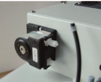
Manual JES-370
Option: Prozessabsperrkugelhahn                                      Option: process shut off ball valve
Der Prozessabsperrkugelhahn dient zur rohgasseitigen                 The process shut off ball valve shuts off the gas flow on
Absperrung des Gasflusses. Zur Betätigung stehen ma-                 the raw gas side. The shut off valve can be operated ma-
nuelle, pneumatische, pneumatische mit Pilotventil oder              nually, pneumatically, pneumatically with pilot valve or
elektrische Ansteuerung zur Auswahl.                                 electrically.

Option: ABS Glasabscheidefilter                                      Option: ABS glass seperator filter
In der unbeheizter Ausführung ist der ABS Glasabschei-               In the unheated version the ABS glass seperator filter is
defilter mit einer Kondensatpumpe ausgerüstet.                       equipped with a condensate pump.Freeze protection is
Ein Frostwächter dient zum Schutz gegen Einfrieren,                  used to protect against super cooling, a heater allows
eine Heizung erlaubt den Betrieb bei tieferen Tempera-               operation at low temperatures
turen.
Option: Prozesssteuerung für Vorfilterrückspülung                    Option: process controller for pre filter back purge
Zur automatischen Prozesssteuerung der Vorfilterrück-                For automatic processing of the pre filter back purge
spülung.                                                             cycle.
Option: Puffertank                                                   Option: air accumulator
Zu Optimierung der Rückspülleistung kann ein lokaler,                A local air accumulator with optional heating can be used
wahlweise beheizter Puffertank eingesetzt werden.                    to optimise the back purge performance.
Option: Kalibriergasanschluss mit                                    Option: calibration port with non return valve
    Art.Nr.           Entnahmerohre (AD 26,9 mm)*                        Part.No.          Sample pipes (OD 26,9 mm)*
 35.00060      1.4571, max. 600°C; L= 1 m                              35.00060      SS316Ti, max. 600°C; l=1 m
 Auf Anfrage   optional 1,5; 2; 2,5 oder 3 m                           On request optional 1,5; 2; 2,5 oder 3 m
 35.00070      Entnahmerohr 1.4841, max. 1100°C; L=1 m                 35.00070      Sample pipe SS314, max. 1100°C; l=1 m
 Auf Anfrage   optional 1,5 m                                          On request optional 1,5 m
 Auf Anfrage   Entnahmerohr Hastelloy C, max. 900°C; L=1 m             On request Sample pipe Hastelloy C, max. 900°C; l=1 m
 Auf Anfrage   optional 1,5; 2 oder 2,5 m                              On request optional 1,5; 2 oder 2,5 m
 35.00050      Entnahmerohr Kanthal, max. 1200°C; L=1 m                35.00050      Sample pipe Kanthal, max. 1200°C; l=1 m
 Auf Anfrage   optional 1,5 oder 2,5 m                                 On request optional 1,5 oder 2,5 m
     In-Situ Vorfilter, 3 µm, 1.4404, max. 550°C, AD 50 mm*              In-Situ pre filter, 3 µm, SS316L, max. 550°C, OD 50 mm*
 35.00703      L= 0,3 m, bis ca. 10 g/m³                               35.00703      L= 0,3 m, up to approx 10 g/m³
 35.00705      L= 0,5 m, bis ca. 20 g/m³                               35.00705      L= 0,5 m, up to approx 20 g/m³
 35.00710      L= 1 m, bis ca. 30 g/m³                                 35.00710      L= 1 m, up to approx. 30 g/m³
 35.00803      L= 0,3 m mit V-Deflektor, bis ca. 10 g/m³               35.00803      L= 0,3 m with V-deflector, up to approx. 10 g/m³
 35.00805      L= 0,5 m mit V-Deflektor, bis ca. 20 g/m³               35.00805      L= 0,5 m with V-deflector, up to approx. 20 g/m³
 35.00810      L= 1 m mit V-Deflektor, bis ca. 30 g/m³                 35.00810      L= 1 m with V-deflector, up to approx. 30 g/m³
                    Verlängerungsrohr für In-Situ Vorfilter*                                Extension tube for In-Situ pre filter*
 35.00910      1.4401 L= 1 m                                           35.00910      SS316 l= 1 m
 35.00920      1.4401 L= 2 m                                           35.00920      SS316 l= 2 m
 35.00925      1.4401 L= 2,5 m                                         35.00925      SS316 l= 2,5 m
 35.00926      Kanthal L= 2,5 m                                        35.00926      Kanthal l= 2,5 m
                Dichtung für Verlängerungs-/Entnahmerohr                               Gasket for extension- /sample tube
 35.00951      Dichtung ¾“, 38 x 27 x 2 mm, SIL C 4430 (320°C)        35.00951    Gasket ¾“, 38 x 27 x 2 mm, SIL C 4430 (320°C)
                                                                     The calibration port allows calibration on the raw gas
Rückschlagventil                                                     side with minimum effort.
Ein Kalibriergasanschluss ermöglicht eine rohgasseitige
Kalibrierung mit minimalem Auswand.

3. Bestellnummern                                                    3. Order codes

*...Sonderlängen auf Anfrage, für mehr Information siehe Datenbät-   *...Other lenghts are available on request, extra data sheets for “JER
ter “JER Entnahmerohre” und “JER-EH Beheizte Entnahmerohre”          sampling pipes” and “JER-EH heated sampling pipes” are available

BA_DE_JES370_v1.4           –––––––––––––––––––––––––– [ 7 / 30 ] ––––––––––––––––––––––––––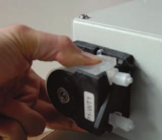
Manual JES-370

   Art.Nr.                  Flanschadapter*                                                          Flanschadapter*
 35.08010     1.4301 DN65/PN6 auf 2 ½“                                  35.08010     SS304 DN65/PN6 to 2 ½“
 35.08030     1.4301 DN65/PN6 auf DN80/PN6                              35.08030     SS304 DN65/PN6 to DN80/PN6
 35.08020     1.4301 DN65/PN6 auf 3“                                    35.08020     SS304 DN65/PN6 to 3“
 35.08040     1.4571 DN65/PN6 auf DN100/PN25                            35.08040     SS316Ti DN65/PN6 to DN100/PN25
 35.01401     Thermische Entkopplung 320mm                              35.01401     Thermal spacer 320 mm
                           Dichtung für Flansch                                                        Flange gasket
 35.00954     Flanschdichtung DN65, SIL C 4430 (320°C)                  35.00954     Flange gasket DN65, SIL C 4430 (320°C)
 35.00957     Flanschdichtung ANSI 2“, SIL C 4430 (320°C)               35.00957     Flange gasket ANSI 2“, SIL C 4430 (320°C)
   Art.Nr.               Zubehör für Gasanschlüsse                       Part.No.           Accessories for gas connections
 35.90080     Einschraubverschraubung 6 mm Rohr, 1.4401                 35.90080    Male connector for 6 mm tube, SS316
 35.90081     Einschraubverschraubung 8 mm Rohr, 1.4401                 35.90081    Male connector for 8 mm tube, SS316
 35.90082     Verschlussstopfen aus 1.4401                              35.90082    Blind plug, SS316
 35.90083     Einschraubverschraubung für 1/4“ Rohr, 1.4401             35.90083    Male connector for 1/4“ tube, SS316
 35.90084     Einschraubverschraubung für 3/8“ Rohr, 1.4401             35.90084    Male connector for 3/8“ tube, SS316
 35.90085     Winkelverschraubung für 6 mm Rohr, 1.4401                 35.90085    Elbow connector for 6 mm tube, SS316
 35.90086     Einschraubverschraubung für 10 mm Rohr, 1.4401            35.90086    Male connector for 10 mm tube, SS316
                    Zubehör für beheizte Messgasleitungen                                     Accessories for heated hoses
 35.00970     PG 42 Verschraubung                                       35.00970    PG 42 fitting
 35.00980     Montageschelle (35...50 mm)                               35.00980    Mounting clamp (35...50 mm)
                                 Verschleißteile                                                      Consumable parts
              Verschleißteilkit bestehend aus 1 x O-Ring A und B,                   Consumable parts kit consisting of 1 x O-ring A and
 35.90104     1 x Filterelement gebundenes SiC, 2 x Flachdich-          35.90104    B, 1 x filter element bonded SiC, 2 x gaskets for high
              tung Kalrez® für Hochtemperatureinsatz                                temperature applications
              Verschleißteilkit bestehend aus 1 x O-Ring A und B,                   Consumable parts kit consisting of 1 x O-ring A and
 35.90105     1 x oberflächenbeschichteten Filterelement, 2 x           35.90105    B, 1 x surface coated filter element, 2 x for high tem-
              Flachdichtung Kalrez® für Hochtemperatureinsatz                       perature applications
 35.90001     O-Ring A, 325°C, Perlast® (FFKM)                          35.90001    O-ring A, 325°C, Perlast® (FFKM)
 35.90002     O-Ring B, 325°C, Perlast® (FFKM)                          35.90002    O-ring B, 325°C, Perlast® (FFKM)
 35.90016     Flachdichtung für Filterelement, 315°C, Kalrez® (FFKM)    35.90016    Gasket for filter element, 315°C, Kalrez® (FFKM)
 35.90009     O-Ring C (ABS Filter), 200°C, Viton® (FKM)                35.90009    O-ring C (ABS filter), 200°C, Viton® (FKM)
 35.90023     ABS Filter Glaskugeln                                     35.90023    ABS filter glass balls
 K3419010     PTFE Paste 113,4 g                                        K3419010    PTFE paste 113,4 g
 12.90392     Schlauchset Kondensatpumpe (5 Stk.)                       12.90392    Hose set condensate pump ( 5 pcs.)
 K1233009A Rollenträger Kondensatpumpe                                  K1233009A   Pulley holder condensate pump
 K1233011     Laufband                                                  K1233011    Tubing cover

          HINWEIS                                                                NOTE
Zum optimalen Betrieb der JES-370 Gasentnahme-                         For optimal performance of the sample gas probe JES-
sonde empfehlen wir die Verwendung von beheizten                       370 we recommend the use of JCT heated sample
JCT Messgasleitungen. Diese sind in unterschiedlichen                  hoses. These are available in different designs and con-
Ausführungen und Endabschlüssen, sowohl für den                        nection configurations for in door and as well for out door
Innen-, als auch für den Außenbereich erhältlich. Weite-               use. Additional installation materials and guidelines for
res Montagematerial und Richtlinien zur fachgerechten                  professional mounting are also available at JCT.
Montage der Heizleitung sind ebenfalls bei JCT erhält-
lich.

BA_DE_JES370_v1.4           –––––––––––––––––––––––––– [ 8 / 30 ] ––––––––––––––––––––––––––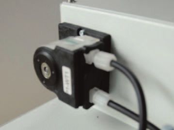
Manual JES-370
Ersatzteile Spare parts
ABS-Filtergehäuse mit Kondensatausgang, ABS filter housing with condensate outlet, 1xGL18 U,
35.90022 35.90022
1xGL18 U, 1xGL18 S 1xGL18 S
35.90026 ABS-Filtergehäuse, 1xGL18 S 35.90026 ABS filter housing, 1xGL18 S
35.90071 T-Griff Nachrüstsatz 35.90071 T-handle assembly kit
35.90025 GL Anschlussverschraubung für ABS Filter 35.90025 GL connector for ABS filter
35.90096 Rückschlagventil 3/8" Kalrez® (320°C) 35.90096 Non return valve 3/8” Kalrez® (320°C)
35.90024 Spannverschluss für ABS Filter 35.90024 Fastener for ABS filter
35.90027 Anschlusskopf (Hastelloy) für ABS Filter 35.90027 Pipe connector (Hastelloy) for ABS filter
35.90260 Temperaturfühler PT 100 35.90260 Temperature sensor PT 100
35.90028 Temperaturschalter Frostwächter 35.90028 Temperature switch for freeze protection
35.90055 Heizelement 115 VAC, 800 W 35.90055 Heater element 115 VAC, 800 W
35.90056 Heizelement 230 VAC, 800 W 35.90056 Heater element 230 VAC, 800 W
35.90058 Heizelement Frostwächter 115 VAC, 125W 35.90058 Heater element freeze protection 115 VAC, 125 W
35.90057 Heizelement Frostwächter 230 VAC, 125W 35.90057 Heater element freeze protection 230 VAC, 125 W
35.90230 Temperaturregler mit Gehäuse 115-230 VAC 35.90230 Temperature controller with housing, 115 -230 VAC
35.90231 Temperaturregler Platine (PCB) 35.90231 PCB temperature controller without housing
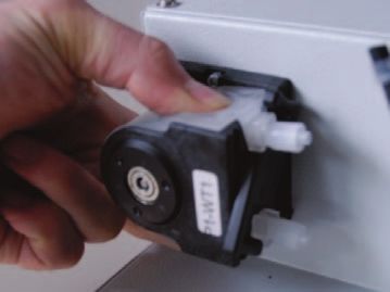
K1233002A Kondensatpumpe komplett K1233002A Condensate pump complete
K1233066 Synchronmotor K1233066 Synchronic motor
K1233014 Pumpengehäuse mit Drehriegel K1233014 Pump housing with latch
K8822416 Ventil Rückspülung 24 VDC K8822416 Back purge valve 24 VDC
K8822429 Ventil Rückspülung 110 VAC K8822429 Back purge valve 110 VAC
K8822419 Ventil Rückspülung 230 VAC K8822419 Back purge valve 230 VAC
K1039023 Puffertank 5 l K1039023 Air accumulator 5 l
K12330XX Puffertank 5 l beheizt K12330XX Heated air accumulator 5 l
35.90301 Steuergerät für Rückspülung 35.90301 Back purge controller
4. Technische Daten 4. Technical data
Betriebsdaten Operational data
Filterelement Keramik, Porengröße 2 µm Filter element Ceramic, pore size 2µm
40/20x135 mm 40/20x135 mm
Option Beschichtet 0,2 µm Option Surface coated 0,2 µm
Filteroberfläche 170 cm2 Filter surface 170 cm2
Arbeitsdruck max. 200 kPa abs. Operating pressure max. 200 kPa abs.
Durchfluss bis zu 180 NL/h, applikati- Flow rate up to 180 NL/h, depends on
onsabhängig application
Gasberührende Materialien 1.4571, SiC; Perlast® Sample gas wetted parts SS316Ti, SiC; Perlast®
Temperatureinstellbereich 5 … 315°C Temperature adjustment range 5 … 315°C
Werkseinstellung 280°C Factory defaults 280°C
Aufheizzeit ca. 45 min Heat up time approx. 45 min
Umgebungstemperatur 5°C...+55°C Ambient temperature 5°C...+55°C
mit Frostwächter -5°C...+55°C with freeze protection -5°C...+55°C
mit beheiztem ABS Filter -10°C...+55°C with heated ABS filter -10 °C...+55°C
Betriebstemperatur Frost- +30°C +/- 3°C Operating temperature +30°C +/- 3°C
wächter freeze protection
Betriebstemperatur ABS Fil- +130°C Operating temperature ABS +130°C
ter filter
Absperrkugelhahn mit pneu- Process shut off valve with
matischem Aktuator pneumatic actuator
Steuerdruck 5...10 barg control pressure 5...10 barg
Luftverbrauch 0,18 l/h gas consumption 0,18 l/h
BA_DE_JES370_v1.4 –––––––––––––––––––––––––– [ 9 / 30 ] ––––––––––––––––––––––––––
Manual JES-370
Durchfluss (Rückspülung)      ca. 90 Nm³/h @ 4 bar             Flow rate (back purging)       approx. 90 Nm³/h @ 4 bar
                              160 Nm³/h @ 7 bar                                               160 Nm³/h @ 7 bar
Luft für Rückspülung          Instrumentenluft nach ISO        Air for back purge             instrument air according to
                              8573-1 Class 1.2.1                                              ISO 8573-1 Class 1.2.1
Schutzart                     Elektronik: IP 65                Protection class               Electronic: IP 65
                              Sonde: IP 43                                                    Probe: IP 43
Einsatzort                    Nur für die Ex -freie Zone zu-   Area classification            For use in safe, non hazar-
                              lässig                                                          dous area only
                       Konstruktion                                                     Construction
Abmessungen über alles        696x613x443 mm BxHxT             Dimension over all             696x613x443 mm WxHxD
Klemmenkasten              340x150x100 mm HxBxT                Junction box                   340x150x100 mm HxWxD
Totvolumen                 177 cm3                             Dead volume                    177 cm3
Montageflansch *1          DN 65, PN 6, Form A nach            Mounting flange *1             DN 65, PN 6, form A accor-
                           EN 1092-1; 1.4571; Stehbol-                                        ding to EN 1092-1; SS316Ti;
Option                     zen M12x41 mm                       Option                         threaded bolts M12x41 mm
                           2“ANSI; 150lbs.; Lochbild                                          2“ANSI; 150lbs., hole pattern
                           nach ASME B16.5; Stehbol-                                          according to ASME B16.5;
                           zen M16x48 mm                                                      threaded bolts M16x48 mm
Einbauwinkel               Empfohlen 5° bis 10° aus            Mounting angle                 range 5° to 10° with respect to
                           der Horizontalen fallend                                           the horizontal, sloping down
Einbaulage                 Verdrehwinkel max. 10°              Mounting position              torsion angle max. 10°
Gewicht                    ca. 30 kg                           Weight                         approx. 30 kg
Gehäusematerial, -farbe    1.4301, Edelstahl natur             Housing material, colour       SS304, stainless steel natural
ABS Filter                 Filterkugeln aus Borosilikat-
                                                               ABS filter                     Filter balls of borosilcate
                           glas
                                                                                              glass
Messgas Eingang            G3/4“ Innengewinde
                                                               Sample gas inlet               G3/4“ female thread
Messgas Ausgang            PVDF Schlauchverschrau-
                                                               Sample gas outlet              PVDF hose fitting DN 4/6
                           bung DN 4/6 mm
                                                                                              mm
Kalibriergasanschluss      6 mm Schottverschraubung,
                                                               Calibration port               6 mm bulkhead union,
(Option)                   1.4401
                                                               (optional)                     SS316
Anschluss Kondensatentsor- PVDF Schlauchverschrau-
                                                               Connection condensate          PVDF hose fitting DN 4/6
gung (Option)              bung DN 4/6 mm
                                                               drain (option)                 mm
Anschluss für Rückspülung 12 mm Schottverschrau-
                                                               Back purge port                12 mm bulkhead union,
                           bung, 1.4401
                                                                                              SS316
Rückspülgasberührte Mate- 1.4401, Messing, EPDM
                                                               Back purge gas wetted ma-      SS316, brass, EPDM
rialien
                                                               terials
Spülgasbedarf                 max. 1500 l/min bzw. max.        Required amount of instru-     max. 1500 l/min respectively
                              450 l/Zyklus @ 7 bara Ein-       ment air                         max. 450 l/cycle @ 7 bara
                              gangsdruck                                                              inlet pressure
Temperatursensor              Pt100                            Temperature sensor             Pt100
Heizelement                   800 W                            Heater element                 800 W
Leistungsaufnahme             ca. 810 VA                       Power consumption              approx . 810 VA
Frostwächter                  125 - 250 W                      Freeze protection              125 - 250 W
Ventil Rückspülung            9 W, 24 oder 115 oder 230        Valve back purge               9 W, 24 or 115 or 230 VAC
                              VAC +/- 10%                                                     +/- 10%
Pilot Ventil                  5 W, 24 oder 115 oder 230        Pilot valve                    5 W, 24 or 115 or 230 VAC
                              VAC +/- 10%                                                     +/- 10%
Elektrischer Aktuator                                          Electrical actuator
 Leistungsaufnahme            6 VA                              power consumption             6 VA
 Anschlussspannung            230 VAC                           power supply                  230 VAC
 Elektrischer Anschluss       Klemmen max. 1,5 mm2              electrical connection         clamps max. 1,5 mm2
Anschlussspannung             230 VAC/50 Hz +/- 10% oder       Power supply                   230 VAC/50 Hz +/- 10% or
                              115 VAC/60 Hz +/- 10%                                           115 VAC/60 Hz +/- 10%
Elektrischer Anschluss        Federzugklemmen                  Electrical connection          Springtype terminal
                              Klemmbereich 0,08...2,5 mm2                                     clamping range 0,08...2,5 mm2
Schaltvermögen Alarmrelais    Typ. 230 VAC/2 A/                Switching alarm relay of       Typ. 230 VAC/2 A/
Rückspülsteuerung             min. 5 VADC/5 mA                 back purge controller          min. 5 VADC/5 mA
Zulassungen / Zeichen         CE                               Approval / Sign                CE
BA_DE_JES370_v1.4          –––––––––––––––––––––––––– [ 10 / 30 ] ––––––––––––––––––––––––––
Manual JES-370
Puffertank Air accumulator
Volumen 5l Volume 5l
Betriebsdruck 0,95 ... 17 bara Operating pressure 0,95 ... 17 bara
Umgebungstemperatur Ambient temperature
unbeheizt 0 ... +100°C without heater 0 ... +100°C
beheizt -10 ... +100°C with heater -10 ... +100°C
Material 1.4301 Material SS304
Versorgungsanschluss Schneidringverschraubung Supply connection Tube fitting DN 10/12 mm
DN 10/12 mm
Betriebstemperatur beheizter +100°C +/- 5°C Operating temperature hea- +100°C +/- 5°C
Puffertank ted air accumulator
Heizung 200 W Heater 200 W
4.1. Druckverlauf 4.1. Pressure characteristics
(bei neuem Filter) (with new filter)
filter & air @ 20°C
100,00
80,00
delta p [mbar]
60,00
2μ Filter
0,2μ Filter
40,00
20,00
0,00
0 400 600 800 1000 1200 1400 1600 1800
Flow [l/h]
4.2. Gasfluss Diagramm 4.2. Flow charts
A2 A2
IN OUT
IN OUT
V1 V1 F1
F1
V2 V2
A0
A0
V3
V3
R1
R1
Condensate drain
Kondensatausgang
Pneumatic actuator
Pneumatischer Aktuator
Pre filter purge
Vorfilter Rückspülung
5. Installation, Sichtkontrolle 5. Installation, unpacking
Nach dem Auspacken ist das Gerät auf allfällige Trans- Check instrument for any damage caused by shipping.
portschäden zu untersuchen. Wurde ein Schaden fest- If any damage is established, contact the carrier and dis-
gestellt, sind unverzüglich die verantwortliche Spedition tributor immediately.
und der Händler zu benachrichtigen.
BA_DE_JES370_v1.4 –––––––––––––––––––––––––– [ 11 / 30 ] ––––––––––––––––––––––––––Manual JES-370
Es ist zu überprüfen, ob die Gerätelieferung Ihrer Bestel- Check instrument and any other parts against order.
lung entspricht.
6. Installationsvorschriften 6. Installation instructions
• Bei Arbeiten am elektrischen Teil des Gerätes ist es • Disconnect mains before working on electrical part
vom Netz zu trennen. of equipment.
• Das Gerät muss entsprechend den örtlich geltenden • The equipment has to be connected and grounded
Vorschriften angeschlossen und geerdet werden. according to the local rules and regulations.
• Für einen sicheren Betrieb der Sonde ist diese mit • In order to guarantee safe operation the electronic
einer verriegelnd abschaltenden Untertemperatur- is equipped with interlocking under temperature mo-
überwachung ausgestattet. Die Rücksetzung erfolgt nitoring. For reset disconnect and connect power
durch spannungsfrei Schalten der Elektronik. again.
• Der Betreiber ist angehalten, den potentialfreien • It is highly recommended to use the volt free status
Statuskontakt zu benutzen bzw. zu überwachen. contact. Only this assures a reliable operation of the
Nur dies gewährt einen sicheren Betrieb der Sonde. probe.
• Es ist zwingend notwendig, die Elektronik vor Strah- • It is essentially necessary to keep the electronics
lungshitze zu schützen. (Thermische Isolation). Die away from radiant heating (thermal insulation). The
maximale Umgebungstemperatur darf 55°C nicht ambient temperature must not exceed 55°C.
überschreiten. • The flange temperature must not exceed 320°C. Ot-
• Die Flanschtemperatur darf 320°C nicht überschrei- herwise a change of construction is necessery, eg.
ten, sonst ist eine konstruktive Änderung, z.B: Ein- use of a thermal spacer.
satz eines Thermal Spacers, notwendig.
• Die Sonde muss immer mit einer Mindestneigung • The probe mounting has to be done always with a
von 5° gegen das Entnahmerohr hin montiert wer- minimum inclination of 5° towards the sampling pipe.
den. Dies ist erforderlich um einen allfällig möglichen This is necessary to prevent a possible flow back
Rückfluss des Kondensates in die Entnahmesonde from condensate into the probe.
zu verhindern.
6.1. Montage 6.1. Mounting
• Entnahmerohr und/oder Vorfilter mit Dichtung am • Mount sampling pipe and/or pre filter with gasket on
Sondenflansch montieren. the flange of the gas sampling probe.
• Sonde mit Dichtung am Prozessflansch montieren. • Mount probe with gasket on the process flange.
• Einbauwinkel gemäß technischer Spezifikation be- • Take care for correct mounting angel according tech-
achten. nical specification.
• ABS-Filtergehäuse mit ABS Filterkugeln befülllen • Fill ABS-filter housing with ABS-filter balls and mount
und mit Spannverschluss am Anschlusskopf mon- it with fastener on the connecting head. Check the
tieren. Auf korrekte Ausrichtung des Filtergehäuses correct alignment of the filter housing (see picture)
(siehe Foto) sowie auf Sitz der O-Ring Dichtung and the fitting of the o-ring gasket!
achten!
BA_DE_JES370_v1.4 –––––––––––––––––––––––––– [ 12 / 30 ] ––––––––––––––––––––––––––Manual JES-370
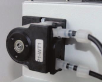
• Beheizte Messgasleitung mit verschiebbarer PG42 • Attach heated sample line with moveable PG42
oder Montageschelle am Gehäuse befestigen und cable conduit or mounting clamp to probe housing
mit dem Anschluss am ABS Glasabscheider gas- and connect it with the connector fitting gas-tight to
dicht verbinden. the ABS glass seperator filter.
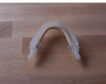
• Schlauch DN 4/6 mm mit Klemmring und Überwurf- • For condensate drain connect DN 4/6 mm tubing
mutter für die Kondensatentsorgung an der Konden- with nut and ferrule to condensate pump and protect
satpumpe anbringen und Ableitung frostsicher drain tubing from freezing.
verlegen.
• Optionalen Puffertank elektrisch und pneumatisch • Connect optional air accumulator electrically and
mit dem Rückspülanschluss verbinden und mit In- pneumatically with back purge connection and sup-
strumentenluft versorgen. ply instrument air.
PG 42 Montageschelle PG 42 Mounting clamp
HINWEIS NOTE
Die beheizte Messgasleitung muss zugentlastet werden The heated sample line must be strain relieved and must
und darf nicht am Fitting abgehängt werden. not be hung on the fitting
ACHTUNG CAUTION
Niemals Fett bei der Montage des Entnahmerohrs ver- Never use grease for mounting sample pipe!
wenden!
BA_DE_JES370_v1.4 –––––––––––––––––––––––––– [ 13 / 30 ] ––––––––––––––––––––––––––Manual JES-370
• Anschluss für Rückspülung: • back purge port connection:
Versorgung mit Instrumentenluft von 3,0 ... 7,0 bar her- Supply instrument air with 3,0 ... 7,0 bar.
stellen.
HINWEIS NOTE
Bei Einsatz eines beheizten Entnahmerohres ist die ent If a heated sample pipe is used follow the corresponding
sprechende Bedienungsanleitung zu beachten. manual.
6.2. Kondensatabtransport (Option) 6.2. Condensate removal (option)
Zur kontinuierlichen Kondensatentsorgung kann die Ga- To ensure continuous removal of condensate the gas
sentnahmesonde mit der Kondensatpumpe JSR-25 aus- samling probe can be equipped with the JSR-25 con-
gerüstet werden(Förderleistung ca. 0,30 l/h). densate pump (approx. capacity 0,30 l/h).
ACHTUNG CAUTION
Betriebsdruckbereich der Kondensatpumpen von 20 - To avoid leakage of the condensate pump the operating
220 kPa abs einhalten! Die Dichtheit der Kondensat- pressure must be between 20 - 220 kPa abs. The tubing
pumpe wird außerhalb dieser Werte beeinträchtigt. Der of the condensate pump is subject to wear and has to
Pumpschlauch ist ein Verschleißteil. Er muss regelmä- be checked regularly and replaced, if necessary.
ßig kontrolliert und bei Bedarf ausgetauscht werden.
ACHTUNG CAUTION
Kondensat kann gefährliche Substanzen enthalten! Das Condensate may contain hazardous substances! The
anfallende Kondensat ist oft sauer. Entsprechende condensate is often acidic. Appropriate safety measures
Schutzmaßnahmen sind bei der Kondensatableitung at the draining point should therefore be taken and reg-
vorzusehen und die einschlägigen Vorschriften sind bei ulations for the disposal of acid liquids should be ad-
der Entsorgung zu beachten! Entsprechende Schutzklei- hered to! Wear appropriate protective clothing!
dung tragen!
6.3. Kalibriergasanschluss (Option) 6.3. Calibration port (option)
• Schlauch für Kalibriergas mit Kalibriergasanschluss • Connect tube for calibration gas gas-tight with cali-
gasdicht verbinden. bration port.
HINWEIS NOTE
Bei Einsatz von Heizleitungen mit zwei frontseitig he- For heated hoses with two inner cores on front side:
rausgeführten Innenseelen: Open connections at check valve and bulkhead con-
Verbindungen bei Prüfventil und Schottverschraubung nector, remove calibration gas pipe and connect calibra-
lösen, Kalibriergasrohr entfernen und Kalibriergasleitung tion tube directly on check valve with the bulkhead
mit Front und Backferrul der Schottverschraubung direkt ferrules
am Rückschlagventil montieren.
BA_DE_JES370_v1.4 –––––––––––––––––––––––––– [ 14 / 30 ] ––––––––––––––––––––––––––Manual JES-370 6.4. Montage an vertikalem Kamin 6.4. Vertical duct installation 6.5. Montage an horizontalem Kamin 6.5. Horizontal duct installation BA_DE_JES370_v1.4 –––––––––––––––––––––––––– [ 15 / 30 ] ––––––––––––––––––––––––––
Manual JES-370

6.6. Montagepositionen                                   6.6. Mounting positions

6.7. Montage In-situ Vorfilter                           6.7. Mounting of In-situ pre filter

BA_DE_JES370_v1.4      –––––––––––––––––––––––––– [ 16 / 30 ] ––––––––––––––––––––––––––
Manual JES-370
6.8. Elektrischer Anschluss                                   6.8. Electrical connections
•     Örtliche Netzspannung, Netzfrequenz und Leis-           •    Check local voltage, frequency and power consump-
      tungsaufnahme mit den Angaben am Typenschild                 tion against type plate.
      vergleichen.                                            •    Connect a 2-pole switch in mains supply; the sample
•     In der Energieversorgungszuführung ist ein 2-poli-           probe is not equipped with a switch.
      ger Netzschalter einzubauen, die Sonde besitzt kei-     •    The equipment has to be connected and additionally
      nen eigenen Netzschalter.                                    grounded with a wire of sufficient diameter on the
•     Das Gerät muss entsprechend den örtlich geltenden            ground connection of the housing according to the
      Vorschriften angeschlossen, sowie zusätzlich über            local rules and regulations.
      den Erdungsanschluss am Gehäuse, mit einem Lei-         •    Always operate contacts within specified ratings. For
      ter ausreichenden Querschnitts geerdet werden.               connection of inductive and capacitive loads use
•     Die Kontakte sind zu jeder Zeit innerhalb der spezi-         suitable protection circuits (f.i. recovery diodes for
      fizierten Werte zu betreiben. Induktive und kapazi-          inductive and serial resistance for capacitive loads).
      tive     Lasten     sind     mit   entsprechenden            Relays are illustrated in current- less conditions (fail
      Schutzmaßnahmen anzuschließen (z.B. Freilaufdio-             safe).
      den bei induktive Lasten und Serienwiderstände bei      •    The operator must provide suitable stress relief
      kapazitiven Lasten). Relais sind in stromlosen Zu-      •    The unit contains no fuse; external fuse on site is re-
      stand (Fail safe) dargestellt.                               quired.
•     Der Betreiber muss eine entsprechende Zugentlas-        •    Terminals are suitable for flexible or solid braided
      tung der Kabel gewährleisten.                                wires from 0,2 ... 2,5mm2
•     Das Steuergerät verfügt über keine Sicherungen.         •    Connect power supply to terminal –X01 according
      Diese sind extern zu stellen.                                to wiring diagram.
                                                              •    Connect status contact to terminal –X01 according
•     Klemmen sind für ein- oder mehrdrähtige Kabel von
                                                                   to wiring diagram.
      0,2 … 2,5mm2 geeignet.
                                                              •    Choose timing intervals according table:
•     Netzanschluss mit Klemme –X01 verbinden (siehe
      Schaltplan).
•     Statuskontakt mit Klemme –X01 verbinden (siehe
      Schaltplan).
•     Rückspül-Intervall nach folgender Tabelle einstellen:
    PLC Input                    Intervall                        PLC Input                    Interval
        I1                       2 Stunden                           I1                         2 hours
        I2                       4 Stunden                           I2                         4 hours
        I3                       8 Stunden                           I3                         8 hours
        I4                      12 Stunden                           I4                         12 hours
        I5                      24 Stunden                           I5                         24 hours

BA_DE_JES370_v1.4         –––––––––––––––––––––––––– [ 17 / 30 ] ––––––––––––––––––––––––––
Manual JES-370
ACHTUNG CAUTION
Die Tür des Gehäuses darf für Installations- und War- Cabinet doors and covers may be removed during in-
tungszwecke nur geöffnet werden, wenn die Verschmut- stallation or maintenance only if there is a negligible risk
zungsgefahr für die Elektrik geringfügig ist. of pollution of the electric / electronic circuits inside.
Die Abdeckung ist sofort nach Beenden der Arbeiten und Covers must be closed immediately after completion of
für Lagerzwecke wieder zu schließen. installation works, maintenance or during storage peri-
ods.
Bei jeglichen Arbeiten am Steuergerät ist das Gerät ab- Disconnect power before repair or maintenance.
zuschalten bzw. vom Netz zu nehmen.
HINWEIS NOTE
Nach Netzanschluss durchläuft das Steuergerät auto- After power supply the unit performs immediately one
matisch einen kompletten Rückspülzyklus. complete back purge cycle.
HINWEIS NOTE
Statuskontakt ist während des Rückspülzyklus aktiv. The status contact is closed while back purge cycle is
active.
6.9. Anschluss von Federzugklemmen 6.9. Connection of spring type terminal
• Feder mit geeignetem Betätigungswerkzeug (2,5 x • Open spring with a suitable tool (2,5 x 0,4 mm).
0,4 mm) öffnen. • Insert cable.
• Leiter einführen. • Release spring.
• Feder entlasten.
7. Temperaturregler Allgemein 7. Temperature controller abstract
Die Elektronik dient zur stetigen Temperaturregelung der The electronic is for continuous temperature regulation
Gasentnahmesonde JES-370. Die Elektronik ist in of the sample gas probe JES-370.The electronic is
einem Gehäuse an der Unterseite der Gasentnahme- mounted on the bottom side of the sample gas probe
sonde JES-370 angebracht. Über den direkt am Son- JES-370. For temperature measurement and regulation
denkörper angebrachten PT100 Temperatursensor wird a PT100 RTD sensor is directly mounted on the body of
der Temperaturwert gemessen und zur Temperaturrege- the heated probe. The monitoring and alarming of low
lung herangezogen. In der Elektronik wird eine Überwa- and high limit temperature and setting of a volt free alarm
chung auf Über- und Untertemperatur durchgeführt, relay is also controlled by the electronic. For safe gal-
wobei diese Grenzwertverletzungen als potentialfreier vanic cut off a security relay with mechanical contacts is
Statuskontakt ausgegeben werden. Zur sicheren galva- wired in series to the solid state relay.
nischen Abschaltung ist seriell zum SSR ein Sicherheits-
relais mit mechanischen Kontakten geschaltet.
BA_DE_JES370_v1.4 –––––––––––––––––––––––––– [ 18 / 30 ] ––––––––––––––––––––––––––Manual JES-370
7.1. Technische Daten Regler 7.1. Technical data controller
Anschlussspannung 115 - 230 VAC +/- 10% Supply voltage 115 - 230 VAC +/- 10%
Leistungsaufnahme ca. 810 VA Power consumption approx. 810 VA
Einstellbereich Solltempera- 5…315°C; in Schritten von Adjustable temperature 5…315°C; in steps of 5°K
tur 5°K range
Einschaltverzögerung 0,5 sec Power-on delay 0,5 sec
Temperaturfühler Pt100 Zweileiter Klasse B Temperature sensor Pt100 two wire class B
Regelgenauigkeit ± 2K Accuracy ± 2K
Alarmtemperaturgrenzen -30°K fix / +20°K fix Alarm limit ranges set values -30°K fix / +20°K fix
Solltemperatur
Alarmverzögerung 10 sec Alarm delay 10 sec
Statusrelais potentialfreier Wechsler Status relay Volt free changeover contact
Schaltvermögen Statusrelais Typ. 230 VAC / 2A / min. Switching capacity status Typ. 230 VAC / 2A / min. 5
5 VADC / 5mA relay VADC / 5mA
Schaltvermögen SSR 1x800W 115/230 VAC Ring- Switching capacity SSR 1 x 800 W 115/230 VAC ring
heizkörper; nullspannungs- heater; zero cross switching
schaltend
Absicherung Schmelzsicherung T 6, Fusing Lead fuse T 6,3 A/230 VAC
3 A/230 VAC
Zulässige Umgebungstem- -30...+65°C Permissible ambient tempe- -30...+65°C
peratur rature
Einschaltdauer 100 % On- time 100 %
Kabeleingang Stromversor- M - Verschraubung 20 x 1,5 Cable entry supply M - conduit 20 x 1,5
gung
Kabeleingang Statuskontakt M - Verschraubung 16 x 1,5 Cable entry status contact M - conduit 16 x 1,5
Anschlussklemmen Klemm- Federzugklemmen Connection terminal Spring type terminal
bereich Cage Clamp® 0,08 mm² - clamping range Cage Clamp® 0,08 mm² -
2,5 mm² 2,5 mm²
Schutzart IP 65 Protection class IP 65
Befestigung Schraubbefestigung an der Mounting Screw connection on gas
Gasentnahmesonde sample probe
Montagelage Vertikal unter dem Sonden- Mounting position Vertical below sample probe
gehäuse housing
Diagnoseanzeige / Betriebs- 3 x LED Diagnostic / Operation indi- 3 x LED
anzeige cator
Gehäuse Außenabmessun- 120 x 160 x 90 mm (HxBxT) Housing dimensions 120 x 160 x 90 mm (HxWxD)
gen
Gewicht Gewicht ca. 0,6 kg Weight approx. 0,6 kg
Zulassungen / Zeichen CE Zulassungen / Zeichen CE
Technische Änderungen vorbehalten. Subject to change without notice.
ACHTUNG! CAUTION!
Sicherung immer durch gleiche Type und Leistung er- Replace fuse always with same type and rating!
setzen!
7.2. Spannungsversorgung 7.2. Power supply
Durch den Einsatz eines Weitbereichsnetzteils ist eine The unit is equipped with a wide range power supply
Versorgungsspannung 90 …230 VAC zulässig. which allows a supply range from 90 to 230 VAC.
ACHTUNG CAUTION
Der Ringheizkörper der Sonde muss entsprechend der The ring heater element must be suitable for the re-
benötigten Anschlussspannung ausgeführt sein! quired supply voltage.
BA_DE_JES370_v1.4 –––––––––––––––––––––––––– [ 19 / 30 ] ––––––––––––––––––––––––––Manual JES-370
7.3. Elektrischer Anschluss 7.3. Electrical connections
7.4. Temperaturüberwachung 7.4. Temperature control
Fällt / Steigt die Temperatur für 10 sec. unter / über die Lowers / rises the temperature for at least 10 sec. under
min. / max. Temperaturgrenze ab, wird die Status LED / over the min. / max. of the temperature boundary the
für Unter- / Übertemperatur aktiviert. Darüber hinaus fällt status LED for under- / over temperature will be acti-
das Statusrelais ab. Bei Übertemperatur wird zusätzlich vated. Additionally the status relay is de-energised. If
der Heizungskreis des SSR galvanisch getrennt. Der the max. temperature boundary is exceeded, also the
Temperaturwert ist +20 /-30 K vom eingestellten Solltem- SSR heater circuit is galvanically disconnected. The
peraturwert. temperature boundary is +20 /-30 K from the adjusted
temperature set value.
Während der Aufheizphase wird Untertemperatur aus-
During the heat up sequence under temperature is indi-
gegeben (LED/Relais) bis die eingestellte Solltemperatur
cated (LED/Relay) until the temperature set value minus
minus der Alarmtemperatur min. (-30 K) erreicht wurde.
the low boundary of -30 K is reached.
Beim Anlegen der Versorgungsspannung läuft eine
For fault suppression during power on a delay of 0,5 sec.
kurze Einschaltverzögerungszeit von 0,5 sec. zur Stör-
is equipped.
unterdrückung ab.
7.5. Heizung 7.5. Heater
Die Heizungsregelung erfolgt über ein von der Regel- The heater control is done by the control electronic with
elektronik gesteuertes Solid State Relais SSR mit einem a solid state relay SSR with a series wired security relays
seriell geschalteten Relais zur sicheren galvanischen for safe galvanic isolation in fault condition. For SSR pro-
Trennung im Fehlerfall. Zum Schutz des SSR ist eine tection a lead fuse rated T 6,3 A is wired in series. Hea-
Schmelzsicherung T 6,3 A in Serie geschaltet. Die Heiz- ting pulses are displayed by the yellow heater LED.
impulse werden mit der gelben Heizung LED angezeigt.
7.6. Störung - Alarm 7.6. Fault - alarm
Das mit potentialfreiem Wechselkontakt ausgestattete The status relays is operated in working principle and is
Statusrelais wird im Arbeitstromprinzip betrieben (d.h. im equipped with a volt free status contact (energised in
Gut Zustand angezogen). Bei aktivem Alarm ist auch good condition). In case of alarm the security relays is
das Sicherheitsrelais abgefallen. Nach 10 sec ununter- also de-energised.If a fault continues uninterrupted for
brochenem Auftreten des Fehlerzustands wird der Alarm 0 sec the alarm is visually displayed and signalled by the
visuell angezeigt und mit dem Statusrelais ausgegeben. status relay.
Kürzere Unterbrechungen führen dabei zu keinen Ab- Short distortions will not be displayed and do not lead to
schaltungen oder Signalisierungen. Die Fehlersignalisie- a fault condition. Failure indication is done by lighting up
rung wird durch Aufleuchten der roten Fehler LED the red LED. The fault code is signalized by short flas-
angezeigt; wobei jeweils durch lange Blinksignale ge- hing LED pulses between long flash pulses (refer to
trennt der Fehlercode mit kurzen Blinkimpulsen signali- table).
siert wird (siehe Tabelle).
The controller locks in fault condition. A resuming of con-
Der Regler schaltet verriegelt ab. Eine Wiederaufnahme trol operation is only possible by power reset (short in-
des Regelbetriebs ist nur durch einen Netzreset möglich terruption of supply voltage).
(kurzzeitige Unterbrechung der Versorgungsspannung).
Always operate contacts under specified ratings. For
Die Kontakte sind zu jeder Zeit innerhalb der spezifizier- connection of inductive and capacitive loads use suitable
ten Werte zu betreiben. Induktive und kapazitive Lasten protection circuits (e.g. recovery diodes for inductive and
sind mit entsprechenden Schutzmaßnahmen anzu- serial resistance for capacitive loads). Relays are illus-
schließen (z.B. Freilaufdioden bei induktiven Lasten und trated in current- less conditions (fail safe).
Serienwiderstände bei kapazitiven Lasten) Relais sind
in stromlosen Zustand (Fail safe) dargestellt.
BA_DE_JES370_v1.4 –––––––––––––––––––––––––– [ 20 / 30 ] ––––––––––––––––––––––––––Sie können auch lesen