JCT ANALYSENTECHNIK GMBH 5/20
←
→
Transkription von Seiteninhalten
Wenn Ihr Browser die Seite nicht korrekt rendert, bitte, lesen Sie den Inhalt der Seite unten
5/20

JCT                      B EDIENUNGSANLEITUNG
A NALYSENTECHNIK G MBH   O PERATING M ANUAL

                         JES-360Ex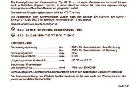
Manual JES-360Ex

Inhalt                                                            Table of Content
1. Einleitung                                             3        1. Introduction                                            3
  1.1. Allgemeine Sicherheitsinformation                  3          1.1. General safety information                          3
  1.2. Bestimmungsmäßige Verwendung                       4          1.2. Intended use                                        4
  1.3. Qualifikation des Personals                        4          1.3. Qualification of the staff                          4
  2.1. Varianten                                          4        2. Description                                             4
3. Bestellcodes                                           6          2.1. Variants                                            4
4. Technische Daten                                       9        3. Order codes                                             6
  4.1. Montage                                            11       4. Technical data                                          9
  4.2. Modular                                            11         4.1. Mounting                                            11
  4.3. Service und Sicherheit                             11         4.2. Versatile                                           11
  4.4. Druckverlauf                                       11         4.3. Service and security                                11
  4.5. Gasfluss Diagramm                                  12         4.4. Pressure characteristics                            11
  4.6. Druck-Temperatur Diagramm Prozessabsperrventil     12         4.5. Flow charts                                         12
  5. Installation, Sichtkontrolle                         12         4.6. Pressure-temperature chart process shut-off valve   12
6. Installationsvorschriften                              12       5. Installation, unpacking                                 12
  6.1. Montage                                            13         6.1. Mounting                                            13
  6.2. Elektrischer Anschluss                             16         6.3. Terminal strip                                      16
  6.3. Klemmleiste                                        16       7. Start up                                                17
7. Inbetriebnahme                                         17       8. Maintenance and service                                 18
8. Wartung und Service                                    18         8.1. Replacement of filter element                       18
  8.1. Ersetzen des Filterelementes                       18       9. Demounting                                              20
9. Demontage                                              20       10. Information about variants                             20
  10.1. Pneumatischer Aktuator für Prozessabsperrventil   20         10.1. Pneumatic actuator process shut-off valve          20
  10.2. Puffertank                                        20         10.2. Air accumulator                                    20
11. Fehlerdiagnose Checkliste                             21       11. Fault diagnostic check list                            21
12. Abmessungen                                           22       12. Dimensions                                             22
1. Zertifikate PTC Heizelement                            27       1. Certificates PTC heater                                 27
2. Zertifikate Klemmkasten                                29       2. Certificates junction box                               29
3. Zertifikate Klemmkasten                                33       3. Certificates junction box                               33

© 2020 JCT Analysentechnik GmbH                                    © 2020 by JCT Analysentechnik GmbH
Reproduktion im Ganzen oder auszugsweise ohne vor-                 Reproduction in whole or in part in any form or medium
herige schriftliche Genehmigung verboten.                          without written permission is prohibited
Alle verwendeten Markenzeichen sind Eigentum der ent-              All trademarks not explicitly mentioned are property of
sprechenden Rechteinhaber.                                         their legal owners.
JCT bietet diese Betriebsanleitung "wie vorliegend" ohne           JCT provides this operating manual "as is" without any
jede Garantie in irgendeiner Art, weder ausdrücklich               warranty of any kind, either express or implied, including
noch stillschweigend, einschließlich Garantien oder Be-            warranties or conditions of merchantability or fitness for
dingungen der Marktgängigkeit oder Eignung für einen               a particular purpose.
bestimmten Zweck.
Technische Änderungen vorbehalten.                                 Subject to technical modifications without notice.

BA_DE_JES360Ex_v1.021                         ––––––––––––––– [ 2 / 38 ] –––––––––––––––––
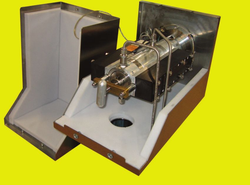
Manual JES-360Ex
1. Einleitung                                                1. Introduction
Die beheizte Gasentnahmesonde JES-360Ex dient zur            The heated gas sampling probe JES-360Ex is designed
kontinuierlichen Entnahme von staub- und aerosol-hal-        for continuous use in extractive sampling systems even
tigen Gasen bei extraktiven Analysensystemen. Wasser-        when the sample contains dust and aerosols. Water va-
dampf und hohe korrosive Gasfeuchte müssen über              pour and high corrosive gases must be kept above their
dem Taupunkt gehalten werden, damit keine Verände-           dew point to prevent corrosion and sample degradation
rung des Gases vor den Analysengeräten oder der Pro-         prior to the analysis or sample conditioning.
benaufbereitung stattfinden kann.
Die Gasentnahmesonde JES-360Ex ist in vielen unter-          The JES-360Ex can be delivered in a lot different versi-
schiedlichen Konfigurationen lieferbar um unterschied-       ons to meet diverse user specific requirements.
lichsten Anforderungen gerecht zu werden.
Die JES-360Ex ist mit einem großflächigen, austausch-        The JES-360Ex incorporates a non-corrosive heated, re-
baren beheizten Keramik-Filterelement ausgestattet.          placeable ceramic filter element. The filter element is
Das Filterelement ist in einem elektrisch beheizten Edel-    mounted in an electrically heated stainless steel housing
stahlgehäuse montiert und zusätzlich in einem thermisch      covered by a thermal isolated weather protection enclo-
isolierten Wetterschutzgehäuse untergebracht. Die JES-       sure. The Model series JES-360Ex is built to be equip-
360Ex Modellreihe kann mit verschiedenen Ventilen und        ped with various valves and a high efficient pre filter and
einer hocheffektiven Vorfilter und Rückspüleinrichtung       back purge techniology “Back Flush”. The gas sampling
“Back Flush” ausgestattet werden. Die Gasentnahme-           probes can be built for different temperature classes T3
sonde kann für unterschiedliche Temperaturklassen T3/        / T4. The temperature regulation is done by a mainten-
T4 gebaut werden. Die Temperaturregelung erfolgt             ance free, self regulating PTC heater elements with low
durch eine wartungsfreie selbtregelnde PTC Heizung mit       temperature alarm.The heated sample hose JHX series
Alarmmeldung für Untertemperatur. Die beheizte Mess-         is directly connected with a moveable PG42 cable con-
gasleitung der Serie JHX wird direkt am Gehäuse der          duit on the probes housing. A universal mounting clamp
Sonde über eine verschiebbare PG42 Verschraubung             is available to connect other types of heated sample
montiert. Für die Montage anderer Heizleitungstypen          hoses. For proper selection of various sample pipe con-
steht eine Montageschelle zur Verfügung. Für eine kor-       structions and materials please refer to our trained staff.
rekte und optimale Auswahl der verschiedenen Entnah-
merohre und Materialien steht Ihnen unser geschultes
Personal gerne zur Seite.

1.1. Allgemeine Sicherheitsinformation                       1.1. General safety information
Messgassonden sind hochentwickelte Geräte, die nur           Sample gas probes are sophisticated devices intended
von qualifiziertem Personal bedient werden dürfen. Es        for use by qualified personnel only. It is necessary that
ist notwendig, dass dieses Handbuch von jenen, die           this manual has been read and understood by those who
diese Geräte installieren, benutzen bzw. warten, gelesen     will install, use and maintain this equipment.
und verstanden wurde. Eine Handhabung des Gerätes            Operation of the applience has to be done also accor-
hat ebenso unter Berücksichtigung der jeweils geltenden      ding to the effective security regulations and rules for ac-
Sicherheitsbestimmungen und Unfallverhütungs- vor-           cident prevention.
schriften zu erfolgen.
Eine Nichtbeachtung kann zu Sach- und / oder Perso-          Nonobservance may lead to personal injury and or ma-
nenschäden führen.                                           terial damage.
Bei Nichtbeachtung der Sicherheitsvorrichtungen und          JCT does not take liability for non observance of security
der in dieser Betriebsanleitung aufgeführten Hinweise        advices, rules and laws which are referenced in this ma-
übernimmt JCT keine Haftung. Dies gilt sowohl bei der        nual. This includes installation, operation, maintenance
Installation, beim Betrieb als auch bei Wartung und Re-      and service and also if it is not written in this manual.
paratur der Geräte, auch dann, wenn in dieser Bedie-
nungs- und Wartungsanleitung nicht ausdrücklich darauf
hingewiesen wird.
Die JCT Analysentechnik GmbH haftet nicht bei eigen-         JCT Analysentechnik GmbH is not responsible for arbi-
mächtigen Änderungen des Gerätes oder für deren un-          trary changes on the device neither for inappropriate
sachgemäße Handhabung oder Verwendung.                       operation or use.
Wenn anzunehmen ist, dass ein gefahrloser Betrieb des        If hazardous free operation of the module is not possible,
Gerätes nicht mehr möglich ist, muss das Gerät außer         the user must stop operation and prevent further use.
Betrieb gesetzt und gegen unbeabsichtigten Betrieb ge-
sichert werden.
Es ist anzunehmen, dass ein gefahrloser Betrieb nicht        Reasons for putting the module out of order are:

BA_DE_JES360Ex_v1.021                    ––––––––––––––– [ 3 / 38 ] –––––––––––––––––
Manual JES-360Ex
mehr möglich ist, wenn:                                        •   Unit is visibly damaged
• das Gerät sichtbare Beschädigungen aufweist                  •   if the equipment does not work any longer
• wenn das Gerät nicht mehr arbeitet                           •   incorrect storage under inappropriate conditions
• nach langer Lagerung unter ungünstigen Verhältnis-           •   if the device has been subject to frequent moving
   sen
• nach schweren Transportbeanspruchungen
1.2. Bestimmungsmäßige Verwendung                              1.2. Intended use
Die Geräte sind nur für den Einsatz in Gasanalysensys-         The appliances are designed for use in gas analysis sys-
temen bestimmt. Bitte Beachten Sie die Angaben in den          tems only. Please observe the technical specifications
technischen Spezifikationen hinsichtlich Umgebungs-            regarding ambient and supply conditions and admissible
und Versorgungsbedingungen sowie zulässige Druck-              pressure and temperature limits.
und Temperaturgrenzen.

1.3. Qualifikation des Personals                               1.3. Qualification of the staff
Für die in dieser Betriebsanleitung beschriebenen Tätig-       For the activities described in these operating instructi-
keiten ist eine entsprechend qualifizierte Fachkraft erfor-    ons, a suitably qualified specialist is required. This ap-
derlich. Dies gilt vor allem für Arbeiten in den Bereichen     plies in particular for work in the fields
• Produktauswahl, Projektierung und Modifikation               • Product selection, configuration and modification
• Montage, Demontage und Lagerung des Geräts                   • Assembly, disassembly and storage of the device
• Installation                                                 • Installation
• Inbetriebnahme                                               • Start up
• Instandsetzung, Reparatur und Reinigung                      • Maintenance, repair and cleaning
Fachkräfte, die diese Tätigkeiten ausführen, müssen            Professionals executing these tasks must have a level
einen Kenntnisstand haben, der relevante nationale Nor-        of knowledge that includes relevant national standards
men und Bestimmungen umfasst.                                  and regulations.

Für Tätigkeiten in explosionsgefährdeten Bereichen sind        For operation in hazardous areas additional knowledge
weitere Kenntnisse erforderlich; empfohlen wird ein Ken-       is necessary; recommended level of awareness as di-
nisstand der in folgenden Normen beschrieben ist:              scribed in the following standards:
IEC/EN 60079-14, IEC/EN 60079-17, IEC/EN 60079-19              IEC/EN 60079-14, IEC/EN 60079-17, IEC/EN 60079-19

2. Beschreibung                                                2. Description
2.1. Varianten                                                 2.1. Variants
Filterelemente aus verschiedenen Materialien                   Filter elements of various materials
•     Keramik                                                  • Ceramic
•     Glasfaser                                                • Glass fibre
•     PTFE                                                     • PTFE
•     Edelstahl                                                • Stainless steel
•     Glaswolle                                                • Pyrex wool

Oberflächenbeschichtetes Filterelement                         Surface coated filter element
Das oberflächenbeschichtete 0,2 µm Filterelement er-           The surface coated 0,2 µm filter element restrains the
schwert die Ablagerung von Staub- und Schmutzparti-            sedimentation of dust and dirt on the filter surface.
keln am Filter.

Prozessabsperrventil                                           Process shut-off valve
Die Gasentnahmesonden JES-360Ex können mit einem               The gas sampling probes JES-360Ex can be equipped
Absperrkugelhahn zur rohgasseitigen Absperrung des             with a process shut-off ball valve to shut off the gas flow
Gasflusses ausgestattet werden.                                on the raw gas side.
Die Steuerung des Ventils kann manuell, pneumatisch            The process shut-off valve is controlled manually, pneu-
oder elektrisch erfolgen.                                      matically or electrically.

BA_DE_JES360Ex_v1.021                      ––––––––––––––– [ 4 / 38 ] –––––––––––––––––

Manual JES-360Ex
Reingasseitige Absperrung                                     Isolation ball valve probe outlet
Die Gasentnahmesonden JES-360Ex können mit einem              The gas sampling probes JES-360Ex can be equipped
Absperrkugelhahn zur reingasseitigen Absperrung des           with a shut-off ball valve to shut off the gas flow on the
Gasflusses ausgestattet werden. z.B Absperrung wäh-           probe outlet. f.i. shut off furing back purge / Back Flush
rend des Rückspül- / Back Flush Vorganges.                    or process.

Anschluss für Sondenfilter Rückspülung                        Back purge port for sample probe filter
Eine periodische Rückspülung des Filterelements mit In-       Periodical back purging of the filter element with instru-
strumentenluft – in Kombination mit dem oberflächenbe-        ment air – combined with a surface coated filter element
schichteten Filterelement – erhöht die Standzeit              – improves the operating life additionally. It is recommen-
zusätzlich. Sie wird bei kleinen Partikeln ab 500 mg/m3       ded for small particles exceeding 500 mg/m3 (e.g. in ce-
(z.B. in der Zementindustrie) und bei größeren Partikeln      ment industry) and for large particles exceeding 1000
ab 1000 mg/m3 empfohlen.                                      mg/m3.

Vorfilter Rückspülung “Back Flush”                            Pre filter back purge “Back Flush”
Hocheffiziente Vorfilter Rückspülung für stark Staubbe-       High efficient pre filter back purge for very dusty enviro-
lastete Bereiche.                                             ments.

Steuerung Filterrückspülung / Vorfilter “Back Flush”          Controller filter back purge / pre filter “Back Flush”
Zur automatischen Ventilsteuerung des Rückspül und /          For automatic valve control of the back purge- and / or
oder Back Flush Prozesses ist ein ein integriertes Steu-      back flush process is an integrated controller available.
ergerät erhältlich.

Anschluss für Kalibriergas                                    Calibration port
Ein Kalibriergasanschluss ermöglicht eine rohgasseitige       The calibration port allows calibration on the raw gas
Kalibrierung mit minimalem Aufwand.                           side with minimum effort.

Rückspül-Steuerventile und Reduktionsventile                  Back purge control valves and reduction valves
Direkt am Sondengehäuse angebaute Rückspül-Steu-              Directly on the probe-mounted backpurge control valves
erventile mit großer Durchgangsöffnung ermöglichen ef-        with a large passage opening allow efficient backpurge
fiziente Rückspülergebnisse bei kompakter Bauweise.           results with compact design. These valves are available
Diese Ventile stehen in mehreren Spulenspannungen             in several coil voltages.
zur Verfügung.                                                To reduce the pressure shocks occurring during the back
Zur Reduzierung der bei der Rückspülung auftretender          purge of the sample gas gas output, the pressure re-
Druckstößen am Messgasausgang kommt das in der                duction valve JBPRV integrated in the connection fitting
Anschlussverschraubung integrierte Druckminderventil          is used.
JBPRV zum Einsatz.

Steuerungen und Pilotventile für Prozessabsperrventil         Actuators and pilot valves for process shut-off valves
Ausführungen der Gasentnahmmesonden mit Prozess-              Versions of the sampling probes with process-side shut-
seitiger Absperrung sind mit einem Volldurchgangs Ku-         off are equipped with a full-bore size ball valve and can
gelhahn ausgestattet welcher manuell, pneumatisch             be operated manual, pneumatic or electrical. A pilot
oder elektrisch Betätigt werden kann. Für pneumatische        valve on the actuator can also be installed for pneumatic
Ansteuerung kann ein Pilotventil am Aktuator ange-            control. For managing the entire backprurge process a
bracht werden. Für den gesamten Steuerungsablauf              back purge controller can be integrated.
kann eine Rückspülsteuerung integriert werden.

Puffertank                                                    Air accumulator
Zur Versorgung der Rückspülung / Back Flush stehen            Unheated air accumulators with a volume of 2 or 5 liters
unbeheizte Puffertanks mit 2 oder 5 Liter Volumen zur         can be used for back purge / Back Flush.
Verfügung.

BA_DE_JES360Ex_v1.021                    ––––––––––––––– [ 5 / 38 ] –––––––––––––––––
Manual JES-360Ex
3. Bestellcodes 3. Order codes
Lieferumfang: Gerät, Befestigungsmaterial, Flanschdich- Scope of delivery: device, mounting material, gasket for
tung, Dichtung für Entnahmerohr, Bedienungsanleitung. flange, gasket for sampling pipe, operating manual.
JES-360 Ex Standard Version JES-360 Ex standard version
JES-360Ex
Basismodell beinhaltet Basic model includes
Back Flush (Vorfilterrückspülung) mit Rückschlagventil (nicht bei Option V0) Pre- filter back flush with non return valve (not for option V0)
Wetterschutzgehäuse Weather protection housing
Selbstlimitierende Heizung Self-limiting heater
Verfügbare Varianten Available Features
Flansch Flange
DN65 5/
/PN6 Z1 DN65 5/
/PN6
2" ANSI Z2 2" ANSI
Filter Filter
2 μm Keramik F1 2 μm ceramic
0,2 μm Keramik oberflächenbeschichtet F2 0,2 μm ceramic surface coated
Prozessabsperrkugelhahn Process shut off ball valve
ohne Absperrkugelhahn und ohne Vorfilterrückspülung V0 without shut off ball valve and without pre-filter back flush
ohne Absperrkugelhahn V1 without shut off ball valve
mit manueller Betätigung V2 with manual operation
mit pneumatischem Aktuator V3 with pneumatic actuator
mit pneumatischem Aktuator und Pilotventil 24 VDC ATEX V8 with pneumatic actuator and pilot valve 24 VDC ATEX
mit pneumatischem Aktuator und Pilotventil 115 VAC ATEX V9 with pneumatic actuator and pilot valve 115 VAC ATEX
mit pneumatischem Aktuator und Pilotventil 230 VAC ATEX V10 with pneumatic actuator and pilot valve 230 VAC ATEX
Heizung (ATEX) Heating (ATEX)
Temperatur Klasse T3, 1 Heizer S0 Temperature class T3, 1 heater
Temperatur Klasse T3, 2 Heizer S1 Temperature class T3, 2 heaters
Temperatur Klasse T4, 1 Heizer S2 Temperature class T4, 1 heater
Temperatur Klasse T4, 2 Heizer S3 Temperature class T4, 2 heaters
Rückspülsteuerventil/Eingang Sondenfilter Back purge valve/port sample probe filter
ohne K0 without
Rückspülanschluss mit Rückschlagventil K1 back purge port with non return valve
Rückspülanschluss mit Rückschlagventil ATEX 24 VDC K5 back purge port with non return valve A
ATEX 24 VDC
Rückspülanschluss mit Rückschlagventil ATEX 115 VAC 50/60Hz K6 back purge port with non return valve A
ATEX 115 VAC 50/60Hz
Rückspülanschluss mit Rückschlagventil ATEX 230 VAC 50/60Hz K7 back purge port with non return valve A
ATEX 230 VAC 50/60Hz
Back Flush-Steuerventil für Vorfilter Rückspülung Pre filter Back Flush valve
ohne J0 without
ATEX 24 VDC J4 ATEX 24 VDC
ATEX 115 VAC 50/60Hz J5 ATEX 115 VAC 50/60Hz
ATEX 230 V VAAC 500/ /60Hz J6 ATEX 230 V VA
AC 50 0//60Hz
Reingasabsperrung Isolation ball valve probe outlet
ohne U0 without
mit manueller Betätigung U1 with manual operation
mit pneumatischem Aktuator U2 with pneumatic actuator
mit pneumatischem Aktuator und Pilotventil 24 VDC ATEX U7 with pneumatic actuator and pilot valve 24 VDC ATEX
mit pneumatischem Aktuator und Pilotventil 115 VAC ATEX U8 with pneumatic actuator and pilot valve 115 VAC ATEX
mit pneumatischem Aktuator und Pilotventil 230 VAC ATEX U9 with pneumatic actuator and pilot valve 230 VAC ATEX
Puffertank Air accumulator
ohne R0 without
Puffertank 2l R1 air accumulator 2l
Puffertank 5l R2 air accumulator 5l
Montageöffnung für Messgasleitung Fitting aperture for heated sample line
Für Montageschelle Durchmesser 35-50mm M1 for mounting clamp diameter 35-50mm
Für Montageschelle Durchmesser 58-61mm M2 for mounting clamp diameter 58-61mm
Anschlüsse Connection ports
Zöllig A1 inch
Metrisch A2 metric
Zusätzliche Optionen Additional Options
andere Others
Kalibriergas Anschluss mit Rückschlagventil C calibration port with non return valve
Untertemperatur Status Kontakt O low temperature status contact
Bestellcode JES-360Ex. Z F V S K J U A - Order code JES-360Ex.
BA_DE_JES360Ex_v1.021 ––––––––––––––– [ 6 / 38 ] –––––––––––––––––
BA_DE_JES360Ex_v1.021
(" )% #' (" & )% ' % * $$ )% $# $"
* $*
Manual JES-360Ex
! #'
'$ *%
$(
*"
'' $ $'
#*
'( #$
*&
)' !$
!"
*# !#
') ('
#
!(
#!
!% )!
*( *)
$"$
## !% *' *) )& )*
(% *( *)
––––––––––––––– [ 7 / 38 ] –––––––––––––––––
/
-.,4/10
,! !* /-
/-,
1
-,4/10
,$
,4/10
,0 -
- /,!
/
-.1,1// 1-./,! /
-.,4/10
,! /-
/-,
. ,
,1// 1-./,$
.
-./, -,. ,-
,!
/
-.1,1// 1-./,! 1, /-.,4/10
,// / ./ ,(&,+,$&,
1,4/10
,4
/ ./ ,(&,+,$&, , ,0 -
- /,!
3
1,
,
,1// 1-./,
,(&,+,$&,
3
1,
,1// 1-./,
,(&,+,$&, , ,. ,-
,!
Manual JES-360Ex

   1     Flansch                                                1    Flange
   2     Gehäusedichtung                                        2    Housing gasket
   5     Mantel                                                 5    Cylinder
   6     Filterelementverschraubung                             6    Filter element screw
   7     Filterelementdichtung                                  7    Filter element gasket
   8     Filterelement                                          8    Filter
   9     Filterhalter Trägerelement                             9    Filter retainer
   10    Filterhalter Dichtkolben                              10    Filter tighting piston
   11    O-Ring B                                              11    O-ring B
   12    O-Ring A                                              12    O-ring A
   13    Abziehbolzen                                          13    Bolt
   15    Schwenkarm                                            15    Pivoting frame
   17    Abziehvorrichtung                                     17    Extractor
   21    T - Griff                                             21    T - handle
   22    Alu Mantel                                            22    Aluminium cover
   25    Wärme Isolation                                       25    Thermal isolation
   26    Gehäuse                                               26    Housing
   27    Erdungsanschluss                                      27    Ground connection pin
   30    PTC Heizer                                            30    PTC heater
   35    Gehäuseverschluss                                     35    Housing lock
   39    Kabelverschraubung Netzanschluss                      39    Cable gland power supply
   45    Messgas Eingang                                       45    Sample gas inlet
   46    Messgas Ausgang                                       46    Sample gas outlet
   47    Anschluss Rückspülung (optional)                      47    Back purge port (option)
   48    Kalibriergas Anschluss (optional)                     48    Calibration gas port (option)
   49    Rückschlagventil                                      49    Non return valve
   51    Untertemperaturkontakt                                51    Low temperature contact
   53    Dichtung für Entnahmerohr                             53    Gasket for sample tube
   54    Flanschdichtung                                       54    Flange gasket
   55    Puffertank                                            55    Air accumulator
   60    Anschlussblock                                        60    Connector block
   61    Anschlusstück                                         61    Connector
   62    O- Ring E                                             62    O-ring E
   63    Kugelhahn reingasseitig                               63    Ball valve on pure gas side
   67    Anschluss für Rückspülventil                          67    port for back purge valve
   69    Pilotventil                                           69    pilot valve
   70    Rückschlagventil                                      70    Non return valve
   72    Prozessabsperrkugelhahn                               72    Process shut off ball valve
   73    Aktuator für Prozessabsperrkugelhahn                  73    Actuator for process shut off ball valve
   74    Magnetventil                                          74    Solenoid valve
   75    Anschluss für Vorfilterrückspülung                    75    Connection for pre-filter back purge
   78    Aktuator für Kugelhahn reingasseitig                  78    Actuator for ball valve on raw gas side
   79    Cu-Dichtung                                           79    Cu-Gasket
  101    Klemmenkasten                                         101   Junction box

BA_DE_JES360Ex_v1.021                   ––––––––––––––– [ 8 / 38 ] –––––––––––––––––
Manual JES-360Ex
4. Technische Daten                                               4. Technical data

                        Betriebsdaten                                                  Operational data

Filterelement                     Keramik, Porengröße 2 µm        Filter element                      ceramic, pore size 2µm
                                       40/20x135 mm                                                       40/20x135 mm
Option                               Beschichtet 0,2 µm           Option                              surface coated 0,2 µm

Filteroberfläche                           170 cm2
                                                                  Filter surface                              170 cm2
Prozessdruck                          max. 2 bara abs.
                                                                  Operating pressure                     max. 2 bara abs.
                                      bis zu 600 NL/h,
Durchfluss                                                                                               up to 600 NL/h,
                                    applikationsabhängig          Flow rate
                                                                                                      depends on application

Gasberührende Materialien            1.4401, SiC, Viton®
                                                                  Sample gas wetted parts               SS316, SiC; Viton®

Temperatur                               max.190°C
                                                                  Temperature                               max. 190°C

Aufheizzeit                              ca. 120 min
                                                                  Heat up time                           approx. 120 min

Zulässige
                                        -20°C...+60°C
Umgebungstemperatur                                               Permissible
                                                                                                           -20°C...+60°C
                                                                  ambient temperature

                                 Q20 ca. 0,5 Nm³/min @ 4 bara
Durchfluss (Rückspülung) 20°C
                                 Q20 ca. 0,6 Nm³/min @ 5 bara                                      Q20 ca. 0,5 Nm³/min @ 4 bara
                                                                  Flow rate (back purging) 20°C
                                                                                                   Q20 ca. 0,6 Nm³/min @ 5 bara

                                 Q20 ca. 0,4 Nm³/min @ 4 bara
Durchfluss (Rückspülung) 100°C                                                                     Q20 ca. 0,4 Nm³/min @ 4 bara
                                 Q20 ca. 0,5 Nm³/min @ 5 bara     Flow rate (back purging) 100°C
                                                                                                   Q20 ca. 0,5 Nm³/min @ 5 bara

                                 Q20 ca. 1,5 Nm³/min @ 4 bara                                      Q20 ca. 1,5 Nm³/min @ 4 bara
Durchfluss (BackFlush) 20°C                                       Flow rate (Back Flush) 20°C
                                 Q20 ca. 2,6 Nm³/min @ 5 bara                                      Q20 ca. 2,6 Nm³/min @ 5 bara

                                                                                                   Q20 ca. 1,3 Nm³/min @ 4 bara
                                 Q20 ca. 1,3 Nm³/min @ 4 bara     Flow rate (Back Flush) 100°C
Durchfluss (BackFlush) 100°C                                                                       Q20 ca. 2,3 Nm³/min @ 5 bara
                                 Q20 ca. 2,3 Nm³/min @ 5 bara
                                                                                                     inert gas or instrument air
                                 Inertgas oder Instrumenten-      Back purge / flush medium                    acc. to
Rückspülmedium                             luft nach                                                   ISO8573.1 class 1.2.1
                                   ISO8573.1 Klasse 1.2.1
                                                                                                        junction box: IP 65
                                     Klemmkasten: IP 65           Protection class
Schutzart                                                                                                  probe: IP 43
                                        Sonde: IP 43

                                                                  Process shut-off valve             temp. max. 200°C @ 7 bar
Prozessabsperrventil             Temp. max. 200°C @ 7 bar

Öffnungsdruck                                                     Cracking pressure
                                            1/psi                                                              1/psi
Rückschlagventile                                                 non return valve

Technische Änderungen vorbehalten                                 Subject to change without notice

BA_DE_JES360Ex_v1.021                        ––––––––––––––– [ 9 / 38 ] –––––––––––––––––
Manual JES-360Ex
Konstruktion Construction
Abmessungen über alles 260 x 419 x 440 mm BxHxT Dimension over all 260 x 419 x 440 mm WxHxD
mit allen Varianten 600 x 659 x 440 mm BxHxT with all variants 600 x 659 x 440 mm WxHxD
Klemmenkasten 170x170x91 mm HxBxT Junction box 170x170x91 mm HxWxD
Totvolumen 180 cm3 Dead volume 180 cm3
Montageflansch *1 DN 65, PN 6, Form A nach Mounting flange *1 DN 65, PN 6, form A according
EN 1092-1; 1.4401 to EN 1092-1; SS316
Option 2“ANSI; 150lbs.; Lochbild Option 2“ANSI; 150lbs., hole pattern
nach ASME B16.5 according to ASME B16.5
Einbauwinkel Empfohlen 5° bis 15° aus der Mounting angle range 5° to 15° with respect to
Horizontalen fallend the horizontal, sloping down
Einbaulage Verdrehwinkel max. 15° Mounting position Torsion angle max. 15°
Gewicht ca. 15 kg Weight approx. 15 kg
mit allen Varianten ca. 25 kg with all variants approx. 25 kg
Gehäusematerial 1.4301 Housing material SS304
Gehäusefarbe Edelstahl natur Housing colour Stainless steel natural
Messgas Eingang G3/4“ Innengewinde Sample gas inlet G3/4“ female thread
Messgas Ausgang 1/8“ NPT Innengewinde Sample gas outlet 1/8" NPT female thread
Kalibriergasanschluss 6 mm Rohrstutzen, 1.4401 Calibration port pipe stubs 6 mm, SS316
Anschluss für Rückspülung 6 mm Rohrstutzen, 1.4401 Back purge port pipe stubs 6 mm, SS316
Anschluss für Back Flush Schottverschraubung, 12mm Back Flush port bulkhead fitting, 12mm
Rückspülmedium berührte Back purge media wetted
1.4401, Messing, EPDM SS316, brass, EPDM
Materialien materials
Heizelement PTC, selbstlimitierend Heating element PTC, self limiting
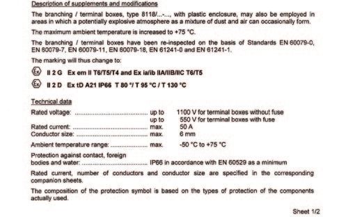
Zündschutzart II 2G Ex d IIC T3 Type of protection II 2G Ex d IIC T3
Heizung “SL Blocktherm” II 2D Ex tD A21 IP65 T200°C heating “SL Blocktherm” II 2D Ex tD A21 IP65 T200°C
II 2G Ex em II T6/T5/T4 II 2G Ex em II T6/T5/T4
Zündschutzart Type of protection
Klemmkasten II 2D Ex tD A21 IP66 junction box II 2D Ex tD A21 IP66
T80°C, T95°C T80°C, T95°C
II 2G Ex mb IIC T4 Gb II 2G Ex mb IIC T4 Gb
Zündschutzart II 2D Ex mb IIIC T130°C Db II 2D Ex mb IIIC T130°C Db
Type of protection
Magnetventile mb IIC T4 Gb mb IIC T4 Gb
mb IIC T130°C Db mb IIC T130°C Db
II 2G Ex h IICT6 Gb II 2G Ex h IICT6 Gb
Zündschutzart II 2D Ex h IIIC T80°C II 2D Ex h IIIC T80°C
Type of protection
Pilotventile ia IIC T6 Ga ia IIC T6 Ga
tb IIIC T80°C Db IP65 tb IIIC T80°C Db IP65
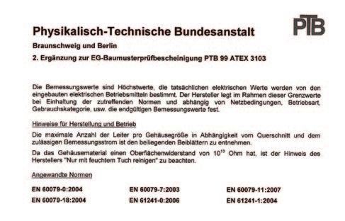
PTB 02 ATEX 1116X PTB 02 ATEX 1116X
Zulassungen / Zeichen Approvals / signs
IECEx PTB 07.0055X IECEx PTB 07.0055X
Heizung heater
PTB 01 ATEX 1016 PTB 01 ATEX 1016
Zulassungen / Zeichen LCIE 02 ATEX 6240 Approvals / signs LCIE 02 ATEX 6240
Klemmkasten IECEx PTB 06.0046 junction box IECEx PTB 06.0046
Zulassungen / Zeichen PTB 14ATEX 2023 X Approvals / signs PTB 14ATEX 2023 X
Magnetventile IECEx PTB 14 0049X solenoid valves IECEx PTB 14 0049X
Zulassungen / Zeichen IECEx PTB 13.0009 Approvals / signs IECEx PTB 13.0009
Pilotventile PTB 09 ATEX 2001 pilot valves PTB 09 ATEX 2001
Elektrik Electric
Anschlussspannung 115...230 VAV 50/60 Hz +/-10% Power supply 115...230 VAV 50/60 Hz +/-10%
Magnetventile 24VDC oder 115VAC oder 230VAC Solenoid valves 24VDC or 115VAC or 230VAC
Pilotventile 24VDC oder 115VAC oder 230VAC Pilot valves 24VDC or 115VAC or 230VAC
Leistungsaufnahme Power consumption
ca. 150 W approx. 150 W
pro Heizelement per heater
Einschaltstrom ca. 2A 230 VAC Inrush current approx. 2A 230 VAC
pro Heizelement ca. 4A 115 VAC per heater approx. 4A 115 VAC
Einschaltdauer 100 % On-time 100 %
BA_DE_JES360Ex_v1.021 ––––––––––––––– [ 10 / 38 ] –––––––––––––––––Manual JES-360Ex
Untertemperaturkontakt Eigensicher Low temperature contact Intrinsically safe
NAT=75°C (NO @ UT) NAT=75°C (NO @ AT)
Schaltvermögen Kontakt max.120 VAC, 1A Switching capacity contact max.120 VAC, 1A
min. 5 VDC/ 1 mA min. 5 VDC/ 1 mA
Wirksame innere Kapazität Effective internal capacitance
Wirksame innere Induktivität Ci = 0,075 nF Ci = 0,075 nF
Li = 0,0Manual JES-360Ex
4.5. Gasfluss Diagramm 4.5. Flow charts
CAL (C) CAL (C)
T0 T0
IN OUT IN OUT
V F1..2 U V F1..2 U
Vorfilter Pre filter
V3 U2 V3 U2
J1..3 J1..3
U3..5 U3..5
V4..6 V4..6
R1..4 K2..4 R1..4 K2..4
Pneumatischer Aktuator Pneumatic actuator
Back Purge (K) Back purge (K)
Pneumatischer Aktuator Pneumatic actuator
Back Flush (J) Back flush (J)
4.6. Druck-Temperatur Diagramm Prozessabsperrventil 4.6. Pressure-temperature chart process shut-off valve
160
140
120
100
p[barg]
80
JES-360Ex
60
40
20
0
0 50 100 150 200 250 300 350
T[°C]
5. Installation, Sichtkontrolle 5. Installation, unpacking
Nach dem Auspacken ist das Gerät auf allfällige Trans- Check instrument for any damage caused by shipping. If
portschäden zu untersuchen. Wurde ein Schaden festge- any damage is established, contact the carrier and distri-
stellt, sind unverzüglich die verantwortliche Spedition und butor immediately.
der Händler zu benachrichtigen. Check instrument and any other parts against order.
Es ist zu überprüfen, ob die Gerätelieferung Ihrer Bestel-
lung entspricht.
6. Installationsvorschriften 6. Installation instructions
• Bei Arbeiten am elektrischen Teil des Gerätes ist es • Disconnect mains before working on electrical part of
vom Netz zu trennen. equipment.
• Das Gerät muss entsprechend den örtlich geltenden • The equipment has to be connected and grounded ac-
Vorschriften angeschlossen und geerdet werden. cording to the local rules and regulations.
• Die Flanschtemperatur darf 200°C nicht überschrei- • The flange temperature must not exceed 200°C.
ten, sonst ist eine konstruktive Änderung, z.B: Ein- Otherwise a change of construction is necessery,
satz eines Thermal Spacers, notwendig. eg. use of a thermal spacer.
Temperaturklasse hinsichtlich Ex-Zone beachten! Please consider Ex temperature class!
BA_DE_JES360Ex_v1.021 ––––––––––––––– [ 12 / 38 ] –––––––––––––––––Manual JES-360Ex
• Der Betreiber ist angehalten, den potentialfreien • It is highly recommended to use the volt free status
Statuskontakt zu benutzen bzw. zu überwachen. contact. Only this assures a reliable operation of the
Nur dies gewährt einen sicheren Betrieb der Sonde. probe.
• Die Sonde muss immer mit einer Mindestneigung • The probe mounting has to be done always with a
von 5° gegen das Entnahmerohr hin montiert wer- minimum inclination of 5° towards the sampling pipe.
den. Dies ist erforderlich um einen allfällig möglichen This is necessary to prevent a possible flow back
Rückfluss des Kondensates in die Entnahmesonde from condensate into the probe.
zu verhindern.
6.1. Montage 6.1. Mounting
• Sonde mit Dichtung am Prozessflansch montieren. • Mount probe with gasket on the process flange.
• Einbauwinkel gemäß technischer Spezifikation be- • Take care for correct mounting angel according tech-
achten. nical specification.
• 1/8“ NPT Einschrauber am Messgas Ausgang mon- • Mount 1/8“ NPT male connector at sample gas out-
tieren. let.
• Beheizte Messgasleitung mit verschiebbarer PG42 • Attach heated sample line on probe enclosure with
oder Montageschelle am Gehäuse befestigen und moveable PG42 cable conduit or mounting clamp.
mit dem Einschrauber gasdicht verbinden. Connect the line with the connector fitting gas-tight.
PG 42 Montageschelle PG 42 Mounting clamp
HINWEIS NOTE
Die beheizte Messgasleitung muss zugentlastet werden The heated sample line must be strain relieved and must
und darf nicht am Fitting abgehängt werden. not be hung on the fitting
VORSICHT CAUTION
Niemals Fett bei der Montage des Entnahmerohrs ver- Never use grease for mounting sample pipe!
wenden!
• Bei Modellen mit Anschluss für Rückspülung: • for models with back purge port:
Instrumentenluftschlauch mit dem Anschluss für Connect tube with instrument air gas-tight with back purge
Rückspülung gasdicht verbinden. port.
6.1.1. Kalibriergasanschluss 6.1.1. Calibration gas port
• Schlauch für Kalibriergas mit Kalibriergasanschluss • Connect tube for calibration gas gas-tight with cali-
gasdicht verbinden. bration port.
BA_DE_JES360Ex_v1.021 ––––––––––––––– [ 13 / 38 ] –––––––––––––––––Manual JES-360Ex 6.1.2. Montage an vertikalem Kamin 6.1.2. Vertical duct installation 6.1.3. Montage an horizontalem Kamin 6.1.3. Horizontal duct installation BA_DE_JES360Ex_v1.021 ––––––––––––––– [ 14 / 38 ] –––––––––––––––––
Manual JES-360Ex
6.1.4. Montagepositionen                                6.1.4. Mounting positions

6.1.5. Montage In-situ Vorfilter                        6.1.5. Mounting of In-situ pre filter

BA_DE_JES360Ex_v1.021              ––––––––––––––– [ 15 / 38 ] –––––––––––––––––
Manual JES-360Ex
6.2. Elektrischer Anschluss 6.2. Electrical connections
• Örtliche Netzspannung, Netzfrequenz und Leis- • Check local voltage, frequency and power consump-
tungsaufnahme mit den Angaben am Typenschild tion against type plate.
vergleichen. • Connect a 2-pole switch in mains supply; the sample
• In der Energieversorgungszuführung ist ein 2-poli- probe is not equipped with a switch.
ger Netzschalter einzubauen, die Messgassonde • The equipment has to be connected and additionally
besitzt keinen eigenen Netzschalter. grounded with a wire of sufficient diameter on the
• Das Gerät muss entsprechend den örtlich geltenden ground connection of the housing according to the
Vorschriften angeschlossen, sowie zusätzlich über local rules and regulations.
den Erdungsanschluss am Gehäuse, mit einem Lei- • The conductor isolation must reach to the terminal.
ter ausreichenden Querschnitts geerdet werden. The conductor itself must not be damaged (nicked)
• Die Leiterisolation muss bis an die Klemme heran- when removing the insulation.
reichen. Beim Abisolieren darf der Leiter selbst nicht • Ensure that the maximum permissible conductor
beschädigt (gekerbt) werden. temperatures are not exceeded by suitable selection
• Durch Auswahl einer geeigneten Anschlussleitung of cables and means of running them. The rated
ist sicherzustellen dass die max. zulässigen Leiter- cross-section of the wire strands from the cable
temperaturen nicht überschritten werden. Der Be- must be at least 1mm² and may not exceed 2,5mm².
messungsquerschnitt der Leitungsadern des Kabels • Always operate contacts within specified ratings. For
muss mindestens 1mm² betragen und darf 2,5mm² connection of inductive and capacitive loads use
nicht überschreiten. suitable protection circuits (f.i. recovery diodes for
• Die Kontakte sind zu jeder Zeit innerhalb der spezi- inductive and serial resistance for capacitive loads).
fizierten Werte zu betreiben. Induktive und kapazi- Relays are illustrated in current- less conditions (fail
tive Lasten sind mit entsprechenden safe).
Schutzmaßnahmen anzuschließen (z.B. Freilaufdio- • The operator must provide suitable stress relief.
den bei induktive Lasten und Serienwiderstände bei
• Fusing has to be done on site according local rules
kapazitiven Lasten). Relais sind in stromlosen Zu-
and regulations.
stand (Fail safe) dargestellt.
• The opening of the terminal connection box must
• Der Betreiber muss eine entsprechende Zugentlas-
only take place in a voltage-free state.
tung der Kabel gewährleisten.
• Eine Absicherung die den örtlich geltenden Vor-
schriften entspricht ist bauseits vorzusehen.
• Die Öffnung des Klemmenanschlusskastens darf
nur im spannungsfreien Zustand erfolgen.
6.3. Terminal strip
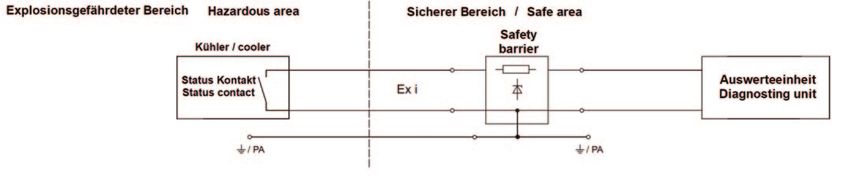
6.3. Klemmleiste Connect the status contacts according to connection di-
Statuskontakte gem. Anschlussschema anschließen. Es agram. It is to be ensured that the potential-free contacts
ist sicherzustellen das die potentialfreien Kontakte durch are operated intrinsically safe by means of on-site mea-
bauseitige Maßnahmen eigensicher betrieben werden sures (e.g. safety barrier, provide proof of intrinsic safety
(z.B. Sicherheitsbarriere, Eigensicherheitsnachweis according EN/IEC 60079-11 chap. 5.7).
nach EN/IEC 60079-11 kap 5.7).
BA_DE_JES360Ex_v1.021 ––––––––––––––– [ 16 / 38 ] –––––––––––––––––Manual JES-360Ex
VORSICHT CAUTION
Dieses Gerät wird mit Netzspannung betrieben. Beim This unit is operated with mains power. During operation
Betrieb dieses Gerätes stehen zwangsläufig bestimmte some parts of the unit are energised with dangerous volt-
Teile dieses Gerätes unter gefährlicher Spannung! age!
Im Betrieb kann das Gehäuse der Sonde sehr heiß wer- During operation the housing of the probe can get very
den. Durch Abnahme des Gehäuses werden heiße Teile hot. Removing the probe housing will expose heated
zugänglich. Bei jeglichen Arbeiten an der Sonde ist das parts. Disconnect power before repair or maintenance
Gerät abzuschalten, die Abkühlung abzuwarten und in and ensure that the internal temperature has dropped to
jedem Fall sind Schutzhandschuhe zu tragen. Beim Be- a safe level before working on it. Always wear heat re-
rühren der internen Teile der Sonde besteht Verbren- sistant gloves. There is burn hazard if necessary precau-
nungsgefahr. tionary steps are not taken.
Bei Nichtbeachtung der Warnhinweise können schwere If these warning notices are ignored possible serious in-
Personenschäden und/oder Sachschäden auftreten. juries and/or damages may be caused.
7. Inbetriebnahme 7. Start up
1. Kontrolle der vorschriftsgemäßen Installation 1. Check of the proper installation
2. Überprüfung des Gerätes auf Beschädigung 2. Review the equipment for damage
3. Während Installation und Inbetriebnahme 3. Ensure that during installation and start up the
Zonenfreigabe sicherstellen. installation site is declared as safe zone.
4. Sicherstellen, dass das Prozessabsperrventil 4. Make sure that the process shut-off valve (vari-
(Variante) geschlossen ist (dh. quer zur Son ant) is closed (i.e. set at right angle to the longi-
den Längsachse steht, bzw. keine Druckluft tudinal axis of the probe, or rather no
oder Strom am Aktuator). compressed air or mains on actuator).
5. Sicherstellen, dass Gerät und Anschlussraum 5. Make sure the unit and connecting room are
sauber sind und sich keine Fremdkörper darin clean and no foreign substances are inside.
befinden. 6. Check all screws, nuts, terminals and cable en-
6. Kontrolle aller Schrauben, Muttern Klemmen tries for a tight fit.
und Leitungseinführungen auf festen Sitz. 7. Check for leaks.
7. Dichtheitsprüfung durchführen.
CAUTION
VORSICHT Before switching on sample probe ensure that the oper-
Vor dem Einschalten ist sicherzustellen, dass die am ating voltage of the unit and the line voltage are identi-
Gerät eingestellte Betriebsspannung und die Netzspan- cal.
nung übereinstimmen. 8. Switch on the power supply of the sample probe.
8. Energieversorgung der Sonde einschalten. After a lead time of approx. 120 min operation
Nach einer Vorlaufzeit von ca. 120 min ist die temperature will be reached. As long as the tem-
Betriebstemperatur erreicht. Solange die Sonde perature is below the set value the fault indica-
den eingestellten Grenzwert nicht überschritten tion contact indicates alarm. (Alarm indication:
hat, signalisiert der Störmeldekontakt den open contact)
Alarmzustand. (Alarmzustand: Kontakt geöffnet) 9. Turn t-handle of process shut-off valve (variant)
9. Prozessabsperrventil (Variante) durch Drehen by 90° to open it (ie. t-handle stands in line with
des T-Griffs um 90° öffnen. (dh. T-Griff steht in probe).
einer Achse mit dem Sondenkörper)
HINWEIS NOTE
Allfällige Geruchsbildung beim erstmaligen Aufheizen ist Any smell at the first time heat up is normal and is no
normal und stellt keinen Gewährleistungsanspruch dar. reason for a warranty claim.
Neue Filterelemente und Dichtungen können in den ers- New filter elements and sealings may influence the mea-
ten Stunden die Messergebnisse beeinflussen. Es wird surement results. It is recommended to purge the gas
empfohlen, die Gasentnahmesonde in aufgeheiztem Zu- sampling probe diligently in heated condition.
stand ausreichend zu spülen.
BA_DE_JES360Ex_v1.021 ––––––––––––––– [ 17 / 38 ] –––––––––––––––––Manual JES-360Ex
HINWEIS NOTE
Die Rückspülung des Filters erfolgt von innen nach With the back purge pulses the filter is cleaned from the
außen. Daher kann etwas Staub im Filterghäuse zurück- inside to the outside. Therefore some dust may remain
bleiben. Das ist normal und beeinträchtigt die Funktion in the filter housing. This is normal and does not harm
der Entnahmesonde nicht. the function of the sampling probe in any way.
Aufgabe von Kalibriergas: Feeding of calibration gas:
1. Kalibriergas mit leichtem Überdruck (ca. 2l/min über 1. Feed calibration gas with minor over pressure (ap-
Druck des Messgasstroms) in Kalibriergasanschluss prox. 2l/min more than sample gas flow) into calibration
einströmen lassen. port.
2. Abströmen des überschüssigen Kalibriergases erfolgt 2. Excess calibration gas flows off into the process.
in den Prozess.
HINWEIS NOTE
Bei vorhandenen sein eines Prozessabsperrhans kann In presence of an process shut off valve, it can be closed
dieser geschlossen werden um Prüfgas zu sparen. to reduce amount of calibration gas.
8. Wartung und Service 8. Maintenance and service
HINWEIS NOTE
Ist es zu Wartungs- oder Reparaturzwecken notwendig, If an item is returned to JCT Analysentechnik, for main-
das Gerät an JCT Analysentechnik zu schicken, ist das tenance or repair reasons, it will only be accepted after
RMA-Formular auf der Website vollständig auszufüllen the RMA form on our website has been completed
(www.jct.at/rma). Andernfalls kann das Gerät zum (www.jct.at/rma). This is to ensure the security of JCT
Schutz der JCT Mitarbeiter nicht übernommen werden. staff.
Recycling Recycling
Das Gerät enthält Bauteile, die wiederverwertet werden The unit contains elements which are suitable for recy-
können, sowie Bauteile, die speziell entsorgt werden cling, and components which need special disposal. You
müssen. Sorgen Sie deshalb dafür, dass das Gerät nach are therefore requested to make sure that the unit will
der Verwendung der Wiederverwertung zugeführt wird. be recycled by the end of its service life.
8.1. Ersetzen des Filterelementes 8.1. Replacement of filter element
Filterelemente und Dichtungen sind Verbrauchsteile und Filter elements, O-rings and gaskets are consumables
sind abhängig von den Einsatzbedingungen regelmäßig, and have to be replaced regularly, at least once a year.
mind. 1mal pro Jahr zu warten. Es ist sicherzustellen, Ensure that sealing surfaces are clean and unhurt.
dass die Dichtflächen sauber und unversehrt sind.
Turning off the heater at ambient temperatures below
Abschalten der Heizung bei Temperaturen unterhalb von -25 °C (~-13 °F) may destroy the sealing materials of the
-25°C kann zu einer Zerstörung der Dichtwerkstoffe füh- gas sample probe.
ren.
HINWEIS NOTE
Die Keramikfilterelemente sind von ihrer Beschaffenheit The ceramic filter elements are very fragile by their na-
sehr zerbrechlich. Daher die Elemente vorsichtig hand- ture. Handle those elements with care and avoid drop-
haben und nicht fallen lassen. ping them.
BA_DE_JES360Ex_v1.021 ––––––––––––––– [ 18 / 38 ] –––––––––––––––––Manual JES-360Ex
Verbrennungsgefahr! Burn hazard!
Hitzebeständige Handschuhe benutzen. Use heat resistant gloves.
VORSICHT CAUTION
Das Gehäuse der Sonde kann sehr heiß sein! The housing of the probe may get very hot!
Bei Prozessüberdruck können explosive und/oder toxi- Take care, in case of process over pressure, explosive
sche Gase austreten. and/or toxic gas emanation is possible.
Entsprechende Maßnahmen sind bei Wartung und Ser- To avoid accidents take care for necessary safety pre-
vice sowie Ersetzen oder Reinigen des Filterelementes cautions in case of service and maintenance.
zu treffen. Während Service und Wartungsarbeiten Zo- Ensure that during service and maintenance works the
nenefreigabe sicherstellen. installation site is declared as safe zone.
VORSICHT CAUTION
Durch Fallenlassen von Teilen kann es möglicherweise Dropping parts can lead to formation of sparks!
zu Funkenbildung kommen!
Bei jeglichen Arbeiten am System darf die Schutzleiter- When carrying out any work on the system the earth
verbindung am Gerät nicht getrennt werden! connection must not be disconnected!
VORSICHT
CAUTION
Durch die Staubkummulation kann es im Inneren der The dust accumulation may lead to the formation of an
Sonde zur Entstehung einer zündfähigen Atmosphäre ignitable atmosphere inside the probe.
kommen.
HINWEIS
NOTE
Gehäusedeckel nicht am Erdungsband abhängen.
Do not use earthing cable to hold weight of housing
cover.
Für den Ersatz der Filterelemente sind folgende Schritte
For cleaning or replacing following steps should be
vorzunehmen: done:
1. Prozessabsperrventil (Option) schließen. 1. Close process shut-off valve (option)
2. Elektrische Zuleitung abschalten und warten bis die 2. Switch off the power supply and wait for cooling
Sonde abgekühlt ist. down of the probe.
3. Wetterschutzhaube abnehmen. 3. Remove the weather protection housing.
4. Durch Drehen des Griffs (Pos. 21) das Filterelement 4. Turn away the handle (pos. 21) for pulling out the
herausziehen. Schwenkarm zur Seite klappen und filter element. Swing the pivoting lever sideways and
Filterkolben herausziehen. pull out the support tube with the filter element.
5. Filterelementverschraubung (Pos. 6) vom Träger- 5. Loosen tighten piston (pos. 6) from the support
element (Pos. 9) lösen. Filterelement und Flach- tube (pos. 9). Pull out filter element and gaskets.
dichtungen herausnehmen.
6. Filter (Pos. 8) und/oder Flachdichtungen (Pos. 7) er-
6. Replace filter element (pos. 8) and/or gaskets (pos.
setzen. Nut am Dichtkolben des Filterhalter Träger-
7). Clean groove on tighting piston of filter retainer
elements (Pos. 10) reinigen und die zwei O-Ringe
(pos. 10) and remove O-rings (pos. 11 and 12) with
mit einem nicht metallischen Werkzeug (Holz- oder
a non-metallic tool (wood or plastic wedge).
Kunststoffkeil) entfernen (Pos. 11 und 12).
7. Neue O-Ringe dünn mit PTFE-Paste benetzen und
7. Apply a thin wetting of PTFE paste on O-rings and
aufziehen.
pull them on.
8. Flachdichtungen (Pos. 7) und Filter (Pos. 8) montie-
8. Remount gaskets (pos. 7) and filter element (pos.
ren.
8).
9. Filterelementverschraubung festziehen (Pos. 6).
9. Screw on the filter element-screw (pos. 6).
10. Dichtungsflächen in der Sonde reinigen.
BA_DE_JES360Ex_v1.021 ––––––––––––––– [ 19 / 38 ] –––––––––––––––––Manual JES-360Ex
11. Anschließend erfolgt Montage in umgekehrter Rei- 10. Clean the sealing surfaces in sample probe.
henfolge.
11. Mount all other parts in vice versa sequence.
NOTE
HINWEIS
Any smell at the first time heat up is normal and is no
Neue Filterelemente und Dichtungen können in den ers- reason for a warranty claim.
ten Stunden die Messergebnisse beeinflussen. Es wird
New filter elements and sealings may influence the mea-
empfohlen, die Gasentnahmesonde in aufgeheiztem Zu-
surement results. It is recommended to purge the gas
stand ausreichend zu spülen.
sampling probe diligently in heated condition.
9. Demontage 9. Demounting
• Sichere Zonenbedingungen in und um das Gerät
• Ensure safe condition in and around appliance.
herstellen.
• Disconnect units supply at site.
• Gerät anlagenseitig spannungsfrei machen.
• Take heated hose regarding its manual out of ser-
• Beheizte Messgasleitung gemäß dessen Bedie-
vice.
nungsanleitung außer Betrieb nehmen.
• Disconnect fitting from sample probe and loosen
• Fitting an der Sonde lösen, verschiebbare PG42
moveable PG42 from cabinet and remove heated
vom Gehäuse lösen und beheizte Messgasleitung
sample gas hose.
entfernen.
• Ensure that sample probe can be removed from pro-
• Sicherstellen, dass Sonde ohne Gefährdung vom
cess without endangerment.
Prozess getrennt werden kann.
• Remove probe from process flange.
• Sonde vom Prozessflansch abmontieren.
• Disconnect cabinet grounding.
• Erdungsanschluss vom Gehäuse trennen.
• Store and dispose with expertise.
• Fachgerechte Aufbewahrung bzw. Entsorgung
10. Informationen zu den Varianten 10. Information about variants
10.1. Pneumatischer Aktuator für Prozessabsperrventil 10.1. Pneumatic actuator process shut-off valve
Den Anschluss des Aktuators mit einem Druckluft- Connect actuator with pneumatic hose. The process
schlauch herstellen. Das Prozessabsperrventil ist ohne shut-off valve is closed when not triggered (failsafe).
Ansteuerung geschlossen (failsafe).
Abmessungen über alles 178 x 461 x 395 mm BxHxT Dimension over all 178 x 461 x 395 mm WxHxD
Gewicht ca. 13,8 kg Weight approx. 13,8 kg
Steuerdruck 2...10 barg Control pressure 2...10 barg
Luftverbrauch 0,18 l/h Air consumption 0,18 l/h
Medium Instrumentenluft nach Medium instrument air acc. to
ISO8573.1 Klasse 1.2.1 ISO8573.1 class 1.2.1
10.2. Puffertank 10.2. Air accumulator
Volumen 2l 5l Volume 2l 5l
Betriebsdruck 0,95...17 bara Operating pressure 0,95...17 bara
Umgebungstemperatur -10...+100°C Ambient temperature -10...+100°C
Material Hochlegierter Stahl, rostfrei Material High alloy steel, non-corrosive
Gewicht ca. 1,7 kg ca.3,6 kg Weight approx. 1,7 kg approx. 3,6 kg
Pneumatische Anschlüsse G 1/2“ Inneng. G 1“ Inneng. Pneumatic connections G 1/2” female G 1” female
BA_DE_JES360Ex_v1.021 ––––––––––––––– [ 20 / 38 ] –––––––––––––––––Manual JES-360Ex
11. Fehlerdiagnose Checkliste 11. Fault diagnostic check list
Störung Ursache / Abhilfe Malfunction Cause / remedy
Kein Betrieb • Spannungsversorgung und Sicherungen
überprüfen No operation • check power supply and fuses
Untertempe- • Betriebsbedingungen sind außerhalb der
ratur techn. Spezifikationen Low tempe- • operating conditions beyond specificati-
Betriebsbedingungen prüfen rature ons
• Wetterschutz mit thermischer Isolierung check operation conditions
fehlt • weather protection with thermal isolation
Wetterschutzgehäuse anbringen not applied
• Elektrischen Widerstand des mount weather protection cover
Heizkörpers überprüfen • check electrical resistance of heater
wenn nötig ersetzen replace if necessary
Falsche • O-Ringe auf Dichtheit überprüfen Wrong mea- • check O-ring sealings
Messergeb- O-Ringe A & B ersetzen surements replace O- rings A & B
nisse
Aktuator / • Ursache feststellen und beseitigen.
Actuator / • find root cause and fix.
Ventilan- Niemals über den manuellen valve drive Never apply manual force via actuator
triebsstrang Aktuatoranschluss Kraft ausüben! train blocked connection!
blockiert Nicht Beachtung kann zu Fehlfunktion Non observance may lead to malfunction
oder Beschädigung des Gerätes führen or damage or damage!
Flow blocked • filter element clogged
Zu geringer • Verstopftes Filterelement
or too low in case of backpurge
oder blo- bei Rückspülung
check correct back purge operation
ckierter Gas- Funktion der Rückspülung überprüfen
fluss Rückspülintervall verkürzen reduce back purge intervall time
Vorfilter überprüfen (wenn vorhanden) check pre filter (if applicable)
Filterelement ersetzen replace filter element
• Betriebsbedingungen sind außerhalb der • operating conditions beyond
technischen Spezifikationen specifications
Zusätzlichen Vorfilter einsetzen Add additional pre filter (with v- deflector)
(mit V-Deflektor)
BA_DE_JES360Ex_v1.021 ––––––––––––––– [ 21 / 38 ] –––––––––––––––––Sie können auch lesen