SMART HOME READY - Loxone
←
→
Transkription von Seiteninhalten
Wenn Ihr Browser die Seite nicht korrekt rendert, bitte, lesen Sie den Inhalt der Seite unten

SMART HOME READY

       Zertifiziert nach
       certified acc. to
       EN ISO 9001:2008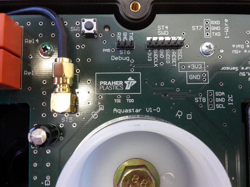
SMART HOME READY

                                   INHALTSÜBERSICHT
1     Urheberrecht                                           4
2     Vorwort zu Bedienungsanleitung                         4
3     Gewährleistungs- und Haftungsansprüche                 5
4     Arbeitssicherheitshinweise                             5
5     Sicherheitshinweise                                    5
6     Restrisiken                                            7
    6.1      Gefährdung durch Strom                          7
    6.2      Gefährdung durch menschliches Fehlverhalten     7
    6.3      Gefährdung durch Strom bei Reinigungsarbeiten   7
7     Allgemein                                              7
8     Bestimmungsgemäße Verwendung                           7
9     Montage                                                8
    9.1      Funktions- und Installationsschema              8
10         Einbinden in die Loxone Config                    9
    10.1     Erstinbetriebnahme:                             9
    10.2     Erneuter Einlernprozess:                        9
11         Elektrischer Anschluss                            11
12         Technische Daten                                  12
13         Anschlussplan für Pumpe und Kugelhahn EO510 ECO   12
    13.1     Anschluss einphasige Pumpe                      12
    13.2     Anschluss drei phasige Pumpe                    12
14         Platinen                                          13
    14.1     Mainboard                                       13
    14.2     Netzteil                                        13
15         Abmessungen                                       14
16         Explosionszeichnung Loxone Aquastar Air           15
17         Demontage Loxone Aquastar Air                     16
18         Zubehör für Loxone Aquastar Air                   17
19         Fehlerbehebung                                    18

www.praherplastics.com                            2
3 www.praherplastics.com
1 Urheberrecht Die Bedienungsanleitung enthält urheberrechtlich geschützte Informationen. Alle Rechte unter Vorbehalt der Praher Plastics Austria GmbH. Die Bedienungsanleitung ist für die Bedienperson bestimmt. Die Vervielfältigung, Reproduktion oder Übersetzung dieser Dokumente in andere Sprachen, ganz oder teilweise, bedarf der ausdrücklichen Genehmigung durch die Praher Plastics Austria GmbH. © 2015 Praher Plastics Austria GmbH Diese Bedienungsanleitung ist in der Absicht geschrieben worden, von denen gelesen, verstanden und in allen Punkten beachtet zu werden, die für den Bereich Loxone Aquastar Air verantwortlich sind. Nur mit der Kenntnis der hier angeführten Hinweise können sie Fehler am Loxone Aquastar Air vermeiden und einen störungsfreien Betrieb gewährleisten. Es ist daher wichtig, dass die vorliegende Dokumentation auch wirklich den zuständigen Personen bekannt ist. 2 Vorwort zu Bedienungsanleitung Diese Bedienungsanleitung soll erleichtern, den Loxone Aquastar Air kennen zu lernen und seine bestimmungsgemäßen Einsatzmöglichkeiten zu nutzen. Die Bedienungsanleitung enthält wichtige Hinweise zum sicheren, sachgemäßen und wirtschaftlichen Betrieb des Loxone Aquastar Air. Ihre Beachtung hilft: Gefahr zu vermeiden Reparaturkosten und Ausfälle zu verhindern die Zuverlässigkeit und Lebensdauer des Loxone Aquastar Air zu erhöhen Die Bedienungsanleitung ergänzt die Anweisungen aufgrund bestehender Vorschriften zur Unfallverhütung und zum Umweltschutz. Sie muss ständig am Einsatzort verfügbar sein und ist von jeder Person zu lesen, die mit dem Loxone Aquastar Air arbeiten will. Dies betrifft: Bedienung, einschließlich Störungsbehebung im Ablauf Pflege Neben der Bedienungsanleitung und den im Verwender Land und an der Einsatzstelle geltenden rechtlichen Regelung zur Unfallverhütung sind auch die anerkannten fachtechnischen Regeln zu beachten. www.praherplastics.com 4
3 Gewährleistungs- und Haftungsansprüche
Gewährleistungs- und Haftungsansprüche bei Personen- und Sachbeschädigung sind
ausgeschlossen, wenn sie auf einen oder mehrere der folgenden Ursachen zurückzuführen
sind.
Nicht bestimmungsgemäße Verwendung des Loxone Aquastar Air
Unsachgemäßes Montieren, in Betrieb nehmen, Bedienen und Warten des Loxone
Aquastar Air
Betreiben des Loxone Aquastar Air bei defekten Sicherheitseinrichtungen oder nicht
ordnungsgemäß angebracht oder nicht funktionsfähige Sicherheits- und
Schutzvorrichtungen
Nichtbeachten der Hinweise in der Bedienungsanleitung bezüglich Montage,
Inbetriebnahme, Betrieb und Wartung des Loxone Aquastar Air
Eigenmächtige bauliche Veränderungen am Loxone Aquastar Air
Mangelhafte Überwachung von Geräteteilen, die einem Verschleiß unterliegen
Unsachgemäß durchgeführte Reparaturen am Loxone Aquastar Air
Fälle durch Fremdkörpereinwirkung und höhere Gewalt am Loxone Aquastar Air
Bei Schäden die durch Nichtbeachten der Bedienungsanleitung entstehen oder Verletzungen
der plombierten Teile, erlischt der Gewährleistungsanspruch.
Für Folgeschäden die daraus resultieren, übernehmen wir keine Haftung!
4 Arbeitssicherheitshinweise
Jede Person, die im Betrieb des Anwenders mit der Montage, Demontage,
Inbetriebnahme, Bedienung und Instandhaltung des Loxone Aquastar Air befasst ist, muss
die komplette Bedienungsanleitung, besonders das Kapitel „Sicherheitshinweise“, gelesen
und verstanden haben.
Die Gebots- und Warnzeichen welche auf Gefährdungen hinweisen sind unbedingt zu
beachten
Gefährliche elektrische Spannung!
Es geht um ihre Sicherheit
5 Sicherheitshinweise
Dieses Gerät wurde nach den Schutzmaßnahmen für elektronische Geräte gebaut und
geprüft und hat das Werk in einem sicherheitstechnisch einwandfreien Zustand verlassen.
Um diesen Zustand zu erhalten und einen gefahrlosen Betrieb sicherzustellen, muss der
Anwender die Sicherheitshinweise beachten, die in dieser Bedienungsanleitung enthalten
sind.
Die Installationsarbeiten dürfen nur von einem befugten und konzessionierten
Elektroinstallateur oder Elektrounternehmen durchgeführt werden.
Dieses Gerät ist nicht dafür bestimmt, durch Personen (einschließlich Kinder) mit
eingeschränkten physischen, sensorischen oder geistigen Fähigkeiten oder mangels
Erfahrungen und/oder mangels Wissen benutzt werden, es sein denn, sie werden durch
einen für ihre Sicherheit zuständigen Person beaufsichtigt oder erhielten von ihr
5 www.praherplastics.com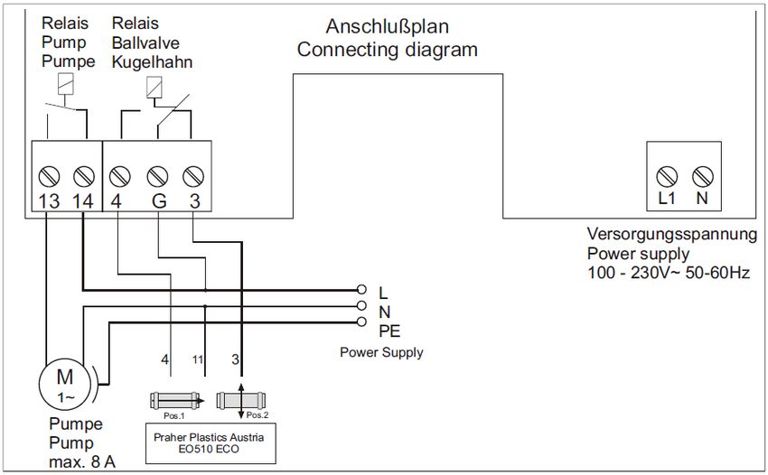
Anweisungen, wie das Gerät zu benutzen ist. Kinder sollten beaufsichtigt werden, um
sicherzustellen dass sie nicht mit dem Gerät spielen.
Die Elektroinstallationen müssen nach den jeweiligen örtlichen und regionalen Vorschriften
(z.B. ÖVE, VDE …) und eventuellen behördlichen Vorschriften ausgeführt werden.
Beim elektrischen Anschluss muss eine Trennvorrichtung in die festgelegte elektr.
Installation eingebaut werden, die es ermöglicht den elektrischen Anschluss allpolig mit
einer Kontaktöffnung von mindestens 3 mm vom Netz zu trennen.
Achten sie darauf, dass die Versorgungsspannung richtig abgesichert ist und ein
Fehlerstromschutzschalter ≤ 30mA installiert ist.
Verwenden sie das Gerät nur in Räumen, in denen keine brennbaren Gase und Dämpfe
vorhanden sein können
Nehmen sie das Gerät nicht sofort in Betrieb, wenn es von einem kalten in einen warmen
Raum gebracht wurde. Das dabei entstandene Kondenswasser kann unter Umständen ihr
Gerät zerstören.
Wenn das Gerät sichtbare Beschädigungen aufweist, nicht mehr arbeitet oder längere Zeit
unter ungünstigen Verhältnissen gelagert wurde, so ist anzunehmen, dass ein gefahrloser
Betrieb nicht mehr möglich ist.
An dieser Stelle ist das Gerät gegen unbeabsichtigte Inbetriebnahme zu sicher, und falls
erforderlich, außer Betrieb zu nehmen.
Beim Öffnen von Abdeckungen oder Entfernen von Teilen, können Spannungsführende
Teile freigelegt werden. Vor einem Abgleich, einer Wartung, einer Instandsetzung oder
einem Austausch von Teilen oder Baugruppen, muss das Gerät von allen
Spannungsquellen getrennt sein, wenn ein Öffnen des Gerätes erforderlich ist, Wenn
danach ein Abgleich eine Wartung oder eine Reparatur am geöffneten Gerät unter
Spannung unvermeidlich ist, darf das nur durch eine versierte Fachkraft geschehen, die
mit den damit verbundenen Gefahren bzw. einschlägigen Sicherheitsvorschriften vertraut
ist.
Kondensatoren im Gerät können noch geladen sein, selbst wenn das Gerät von allen
Spannungsquellen getrennt wurde.
Montage- bzw. Demontage der Armaturen nur im drucklosen Zustand (d.h. Rohrleitung
vorher entleeren).
Bei Armaturen Durchflussrichtung bzw. Fließrichtung beachten!
Jede Person, die sich mit der Bedienung und Instandhaltung des Gerätes
befasst, muss diese Anleitung gelesen und verstanden haben!
Es geht um ihre Sicherheit!
www.praherplastics.com 6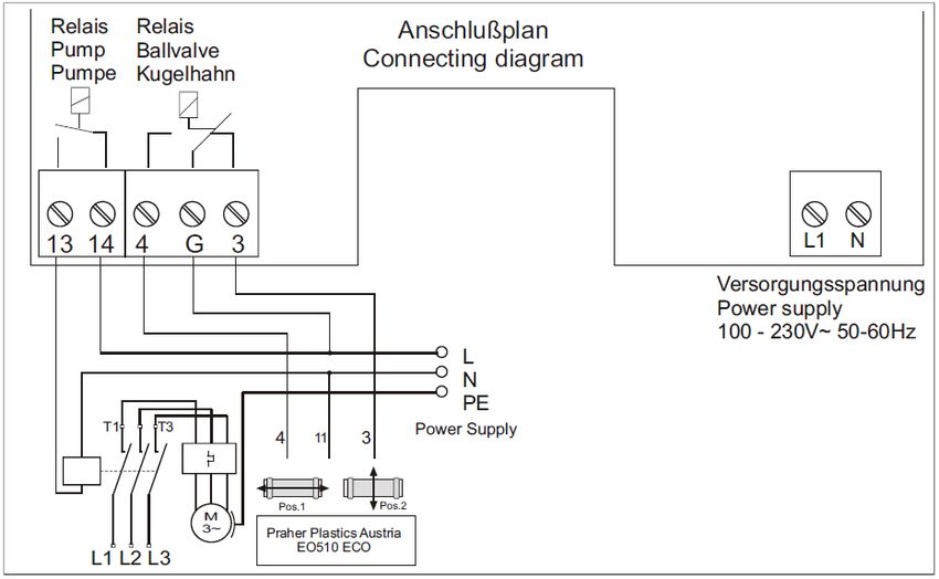
6 Restrisiken
6.1 Gefährdung durch Strom
Manipulationen am Loxone Aquastar Air sind für die Bedienperson
strengstens verboten und dürfen nur von geschulten und befugten Personen
vorgenommen
werden. Die dazugehörigen Ge- und Verbotszeichen sind zu beachten.
6.2 Gefährdung durch menschliches Fehlverhalten
Die Bedienpersonen sind hinsichtlich der Restgefährdung durch elektrischen
Strom sowie der korrekten Bedienung zu unterweisen, sowie auf die
Wirksamkeit der Unterweisung zu kontrollieren.
6.3 Gefährdung durch Strom bei Reinigungsarbeiten
Reinigungsarbeiten am Loxone Aquastar Air dürfen nur im spannungslosen
Zustand durchgeführt werden.
7 Allgemein
Praher Plastics Austria Aquastar Steuerungen sind hochwertige technische Produkte, die
mit großer Genauigkeit und nach modernsten technischen Fertigungsmethoden hergestellt
werden. Sollten trotzdem berechtigte Beanstandungen vorhanden sein, werden diese
natürlich schnellstmöglich behoben. Für das Gerät gilt eine Gewährleistung nach geltendem
EU-Recht. Als Beginn der Gewährleistungsfrist gilt das Kaufdatum.
ACHTUNG! Zur Entlastung der Dichtung steht das Ventil auf einer
Zwischenstellung und ist nicht dicht! Vor Verwendung muss der Antrieb
elektrisch auf Position “Filtern“ gestellt werden
8 Bestimmungsgemäße Verwendung
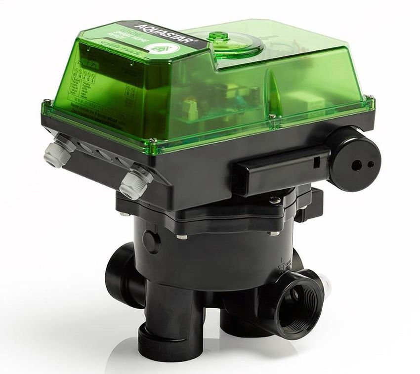
Es handelt sich hierbei um eine Steuereinheit für ein Praher 6 Wege-Ventil die mit einem
Miniserver von Loxone betrieben wird.
Mit einem Loxone Aquastar Air wird vollautomatisch ein Filter per Zeit und Druck
rückgespült und die Pumpe eines Schwimmbades angesteuert sowie diverse Erweiterungen
für die Loxone Steuerung zur Verfügung gestellt.
Es besteht eine zusätzliche elektrische Anschlussmöglichkeit für einen Praher Kugelhahn
EO510 der während des Zyklus öffnet
Der Aquastar darf nie ohne Praher V6-Ventil betrieben werden da ansonsten
Schäden am Gerät entstehen können
7 www.praherplastics.com9 Montage
Geräteinstallation - Installation des Ventils
Binden sie das Ventil entsprechend der Beschriftung und der folgenden Skizze in die
Rohrleitung ein. Verwenden sie Übergangsverschraubungen. Dichten sie bei
Gewindeanschlüssen nur mit Teflonband ab. Das Gerät ist zwar in jeder Lage
funktionsfähig, darf jedoch nicht mit dem Stellantrieb nach unten montiert werden. Bei
einem Niveauunterschied von mehr als 3 Meter im System und Speicher, sollten
Absperr- oder Rückschlagventile eingebaut werden. Ansonsten können zu große Drücke
und Strömungen im Ventil, den Stellantrieb und das Ventil schwer beschädigen. Da beim
Rück- und Nachspülen das Filtermedium ausgespült werden kann, empfehlen wir eine
Drossel in die Kanalleitung einzubauen. Ansonsten kann ein festsitzen des Ventiltellers
auftreten und die einwandfreie Funktion des Aquastars beeinträchtigen. Bei verschmutzen
oder körnigen Medien sind entsprechende Vorfilter einzubauen.
WICHTIG! Während dem Ablauf eines Zyklus muss sichergestellt sein, dass die
Filterpumpe ausgeschaltet ist!
Der Praher Plastics Austria Loxone Aquastar Air ist für die 6-Wege Ventile von Praher
zugelassen. Bei allen anderen Ventiltypen können Fehlfunktionen auftreten da nicht
garantiert werden kann, dass diese mit Abmaßen der Praher 6 Wege Ventile
übereistimmen.
9.1 Funktions- und Installationsschema
Filtern
Filtern der der Flüssigkeit
Flüssigkeit Entleeren
Entleeren vom vom Becken
Becken
(z.B. Wasser)
(z.B. Wasser) mit mit
der der
Pumpe
Pumpe
Becken
Becken→ Pumpe
PumpeVentil Becken Pumpe
Becken→ Pumpe
(zum Filter) Filter Ventil Kanal
→ Ventil (zum
Ventil (vom Filter)
Filter)→ Filter → Ventil→ Kanal
→
BeckenVentil (vom Filter)→ Becken
Filtermedium
Filtermedium reinigen
reinigen (z.B. Umpumpen
Umpumpen der Flüssigkeit
der Flüssigkeit
Sand)
(z.B.imSand)
Gegenstrom
im Gegenstrom ohne Filter
ohne (Filter
Filter ist ist überbrückt)
(Filter
(umgekehrte
(umgekehrteDurchfluss-
Durchflussrichtung im Filter) überbrückt)
richtung im Filter)
Becken→ Pumpe
Becken Pumpe Ventil
Becken→
Becken PumpeVentil
Pumpe → Ventil→ Becken
Becken
→ Filter)
(vom Ventil (vom
FilterFilter)→ Filter
→ Ventil
Ventil (zum Filter)→
(zum Filter) Kanal Kanal
=Klarspülen
Filtermedium reinigen Pump Pump → von Pumpe
von Pumpe
Filtermedium reinigen(z.B.
(z.B. Sand) nach dem Rückspülen
Sand) nach dem Rück- Top → zum Filter
Topzum Filter
spülen
Becken→ Pumpe Bottom → vom Filter
→ VentilPumpe
(zum Filter)→ Bottom vom Filter
Becken Ventil Filter
→Filter)
(zum Filter Filter)→ Kanal
Ventil (vom Return → zum Becken
zum Becken
Return
Ventil (vom Filter) Kanal
Waste → zum Kanal
zum Kanal
Waste
6 Wege Ventilausführung: 11/2“ und 2“
Anschlüsse: Gewinde oder Klebe (alle Anschlüsse offen)
Max. Betriebsdruck: ABS 11/2“, 2“ 3,5 bar
GFK 11/2“, 2“ 6 bar
www.praherplastics.com 810 Einbinden in die Loxone Config
Damit der Loxone Aquastar Air eingelernt werden kann, muss diese zunächst in den
Lernmodus versetzt werden.
10.1 Erstinbetriebnahme:
Wenn die Spannungsversorgung zum ersten Mal eingeschaltet wird, startet der Lernmodus
automatisch.
10.2 Erneuter Einlernprozess:
Möchten Sie den Loxone Aquastar Air neu einlernen, kann der Lernmodus jederzeit auch
manuell gestartet werden. Drücken Sie dazu die Lerntaste für mindestens 5 Sekunden. Der
Loxone Aquastar Air befindet sich nun im Lernmodus.
Die Lerntaste befindet sich auf der Platine (rot eingekreist). Bitte darauf achten, dass die
beigelegte Antenne angeschlossen ist (gelb eingekreist).
Sobald sich das Gerät im Lernmodus befindet, blinken die Status LEDs abwechselnd rot-
grün-gelb.
9 www.praherplastics.comVerbinden Sie sich nun mit Ihrem Miniserver und schalten den Air Monitor ein. Klicken Sie dazu auf die Air Base Extension und aktivieren die Checkbox "Air Monitor". Als nächstes klicken Sie im Lernmonitor auf "Suche Starten". Es werden nun alle Air Geräte gelistet, die sich im Lernmodus befinden. Markieren Sie den Aquastar Air, anschließend geben Sie eine Bezeichnung ein und klicken auf „Gerät erstellen“. Im Peripherie Baum wird nun das Gerät gelistet. Folgende Objekte stehen in der Programmierung zur Verfügung: Neben den klassischen Funktionen eines 6-Wege-Ventils verfügt der Loxone Aquastar Air auch noch über eine 2 analoge Eingänge (1x 0-10V, 1x 0,5-4,5V), 3 frei programmierbare Relais sowie eine 1-Wire Schnittstelle für zum Beispiel Temperatursensoren. Eine ausführliche Beschreibung der einzelnen Objekte, sowie des Poolsteuerungs-Bausteins, welcher die gesamte Poolsteuerung koordiniert und visualisiert, finden Sie online unter www.loxone.com/aquastar www.praherplastics.com 10
11 Elektrischer Anschluss
a) Anschluss der Versorgungsspannung
L1 N 100 – 240 V AC 50/60 Hz ~
b) Anschluss für Pumpe
Potentialfrei: 250VAC 8A bei cosφ=1, 30VDC 8A
13 14 (Bei größeren Lasten muss ein Hilfsrelais verwendet werden)
Auf Position Filtern, Nachspülen, Zirkulieren, Entleeren und nach Ablauf von
ca. 10 sec sind die Klemmen [13 →14] durchgeschaltet.
c) Anschluss für Kugelhahn
Potentialfrei: 250VAC 8A bei cosφ=1, 30VDC 8A
4 G 3 (Bei größeren Lasten muss ein Hilfsrelais verwendet werden)
NO COM NC
Bei ausgeschaltetem Antrieb, auf Position Filtern, Zirkulieren und geschlossen
werden die Klemmen [G→3] durchgeschaltet. Auf Position Entleeren und
während des gesamten Rückspülzyklus sind die Klemmen [G→4]
durchgeschaltet.
d) Potentialfreie Relais
REL1 REL2 REL3
Potentialfrei: 250VAC 5A bei cosφ=1, 30VDC 5A
(Bei größeren Lasten muss ein Hilfsrelais verwendet werden)
Die potentialfreien Relais Rel1 bis Rel3 die als Schließer-Kontakte ausgeführt
sind und dienen als Funktionserweiterung im Loxone System.
e) Drucksensor für Loxone Drucksensoren (Systemdruck oder Niveau)
+24V PS1 GND
Die Klemme PS1 ist für eine Auswertung von 0-10V gedacht die maximale
Spannung beträgt 10V. Hierbei ist der Loxone Drucksensor 0…0,3 Bar oder
0…6 bar optional vorgesehen.
f) Drucksensor für Praher Drucksensoren (Systemdruck)
Die Klemme PS1 ist für eine Auswertung von 0,5-4,5V gedacht die maximale
+5V PS2 GND
Spannung beträgt 5V. Hierbei ist der Praher Drucksensor 0…6 Bar optional
vorgesehen.
Anschluss: Klemme +5V Kontakt Sensor 1
Klemme PS2 Kontakt Sensor 2
Klemme GND Kontakt Sensor 3
g) 1-Wire Schnittstelle
VDD DQ GND Diese Schnittstelle ist zum Anschluss für 1-Wire Sensoren von Loxone gedacht.
h) SMA Antennenstecker
Die Antenne liegt bei und muss unbedingt bei SMA Antennenstecker ST5
angeschlossen sein damit eine Verbindung zum Miniserver aufgebaut werden
kann
11 www.praherplastics.com12 Technische Daten Spannung: 100-240V AC 50/60 Hz Schutzart: IP 65 Frequenz: 50-60 Hz max. Eigenverbrauch: 15 W 11/2“, 2“ 13 Anschlussplan für Pumpe und Kugelhahn EO510 ECO 13.1 Anschluss einphasige Pumpe 13.2 Anschluss drei phasige Pumpe www.praherplastics.com 12
14 Platinen

14.1 Mainboard

14.2 Netzteil

                 13   www.praherplastics.com
15 Abmessungen
1 ½” SM 1 ½” TM 2” SM 3” SM
A 99,5 X 110 170
B 90 X 114 165
C 29,5 31,5 38 50
D 48 47 60 85,5
E 61,5 59,5 81 110
F 163,5 160 210 306
G 304 300 348 445
H 39 42,5 36 50
I 87,5 90 114 165
J 117 117 117 117
K 175 180 228 117
L 125 125 125 330
M 165 165 165 125
N 140 140 140 165
O 18,5 18,5 26 35
P X 62,5 X X
Dimensionen in mm
www.praherplastics.com 1416 Explosionszeichnung Loxone Aquastar Air
1
2
7
9
3
4
10
5
1. Aquastar Gehäusedeckel mit
Moosgummischnur 6
2. SK-Schraube
3. Getriebemotor
4. Aquastar Gehäuseboden 8
5. Gerätestecker und Kabel
für Drucksensor
6. V6ND Ventil 1 ½“, 2“
7. Steuerplatine
8. Drucksensor
9. Pumpenendschalter
10. Ventilteller mit O-Ringen und
Feder
15 www.praherplastics.com17 Demontage Loxone Aquastar Air Für die Demontage des elektronischen Steuerkopfes vom Ventil wird ein Steckschlüssel mit Schlüsselweite 15 mm benötigt. Montage in umgekehrter Reihenfolge (Schritt 1 – 8) ausführen. Schauglas (Schritt 2) und SK-Schraube (Schritt 4) handfest (4 Nm – 8 Nm) montieren. www.praherplastics.com 16
18 Zubehör für Loxone Aquastar Air

   Notgriff                                    Aquastar
   Art.Nr. 101862                              SafetyPack

             Schmutzfilter S4                                    Rückschlagventil S6

   d    DN      A     Z     t       D     PN         D      DN    A         Z       t       D      PN
   50   40      95   104   31,5    101    16         50     40    77        87     31,5   101,5    16
   63   50     109   121   38,5   124,5   16         63     50    87        99     38,5   115,3    16

                     PVC Kugelhahn DN32 – DN50 S6 EO510 ECO 230V

                                                                    PVC                    S6
                                                                       DN          32       40      50
                                                                        d          40       50      63
                                                                       G         1 1/4“   1 1/2“    2“
                                                                       A           77       77       87
                                                                       D         101,5    101,5    115,3
                                                                        E        138,5    138,5    143,5
                                                                       H          159      159      164
                                                                        t         26,5     31,5     38,5
                                                                        Z          87       87       99
                                                                       PN          16       16       16
                                                                  max. bar         3        3       3

                                                17                                        www.praherplastics.com
19 Fehlerbehebung
Antrieb dreht ständig im Kreis ohne eine Position anzufahren
o Gerät wurde ohne zugehörigen Ventil betrieben
Zur Reparatur senden da in diesem Fall bereits ein Defekt vorliegt
Antrieb löst ständig den Rückspülzyklus aus
o Im System befindet sich eine Druckerhöhende Komponenten (z.B.
Solarabsorber)
Drucksensor so einstellen, dass der Loxone Aquastar Air auch bei
erhöhten Druck nicht auslöst
Pumpe schaltet nicht ein bzw. nicht aus
o Relais verschmort
Der maximale Pumpenstrom von 8A wurde überschritten
o Pumpe ist fehlerhaft angeschlossen
Die Pumpe muss immer über die Kontakte 13-14 geschliffen werden
Teller hebt schwer oder Antrieb läuft unregelmäßig bzw. Strömungsgeräusche
sind zu vernehmen
o Die Pumpe wird beim Anheben des Ventiltellers nicht ausgeschaltet
Die Pumpe muss immer über die Kontakte 13-14 geschliffen werden
o Das Gefälle von Wasseroberkannte bis zur Ventil ist zu hoch
Es ist darauf zu achten, dass die Gesamtwassersäule 3m nicht
übersteigt.
o Das V6-Ventil ist verschmutzt bzw. Fremdkörper blockieren das Ventil
Ventil Reinigen und Vorfilter verwenden
www.praherplastics.com 18Notes Notizen 19 www.praherplastics.com
SMART HOME READY

                                       Table of Contents
1     Copyrights                                                     4
2     Introduction to operation manual                               4
3     Warranty and liability                                         5
4     Instructions for safety at work                                5
5     Safety instructions                                            5
6     Residual Risk                                                  7
    6.1      Hazard generated by current                             7
    6.2      Hazard generated by human error                         7
    6.3      Hazard generated by current during cleaning work        7
7     General                                                        7
8     Directions for use                                             7
9     Assembly                                                       8
    9.1      Function- and installation diagram                      8
10         Add the Device into the Loxone Config                     9
    10.1     Initial setup                                           9
    10.2     Re-learning in process:                                 9
11         Electrical Connection                                     11
12         Technical data                                            12
13         Connection diagram for pump and Praher ball valve EO510   12
    13.1     Connection diagram for one phase pump                   12
    13.2     Connection diagram for three phase pump                 12
14         Circuitboards                                             13
    14.1     Mainboard                                               13
    14.2     Power Supply                                            13
15         Dimensions                                                14
16         Exploded view drawing Loxone Aquastar Air                 15
17         Dismantling Loxone Aquastar Air                           16
18         Loxone Aquastar Air Accessories                           17
19         Troubleshooting                                           18

www.praherplastics.com                            2
3 www.praherplastics.com
1 Copyrights
This operation manual contains copyright protected information. All rights reserved to
Praher Plastics Austria GmbH.
This operation manual is designed for use by operating personnel only. Copying,
reproduction or translation of the present document into other languages in whole or
in part is subject to express written permission by Praher Plastics Austria GmbH.
© 2015 Praher Plastics Austria GmbH
Knowledge of the instructions contained in this operation manual is indispensable for
preventing failure and ensuring faultless operation of the Loxone Aquastar Air. Therefore, it is
essential, that the person in charge of operating the equipment is familiar with the present
documentation
2 Introduction to operation manual
This operation manual is intended to facilitate familiarization with the Loxone Aquastar Air and
utilization of the same for the intended purpose.
This operation manual contains important information for safe, proper and economical
operation of the Loxone Aquastar Air. Compliance with these instructions will contribute to
preventing danger
reducing repair costs and equipment failure, and
increasing the liability and service life of the Loxone Aquastar Air
This operation manual supplement the instructions provided by existing accident prevention
and environmental protection regulations. It must be available at the place of utilization of the
equipment at any time and must be read by each person intending to use the Loxone Aquastar
Air . This means
operation, including
correction measures in case of faulty operation and
maintenance
In addition to the operation manual and the compulsory accident prevention regulations
applicable at the place of utilization of the equipment, the generally subject specific technical
rules must be taken into account.
www.praherplastics.com 43 Warranty and liability
Warranty and liability claims in the context of damage to person or property shall be excluded
where such damage results from one or several of the causes listed below:
Improper use of the Loxone Aquastar Air
Improper installation, putting into operation, operation and maintenance of the Loxone
Aquastar Air
Operation of the Loxone Aquastar Air with defective or improper safety devices
Non-compliance with the instructions contained in the operation manual for installation,
putting into operation, operation and maintenance of the Loxone Aquastar Air
Unauthorized modification of the Loxone Aquastar Air
Insufficient monitoring of components subject to wear and tear
Inadequately performed repair of the Loxone Aquastar Air
Damage of the Loxone Aquastar Air resulting from foreign matter or Force Majeure
Enduring damage due to neglect of the operation manual or due to damaging sealed parts
lead to a lapse of the warranty. We do not take any liability for resulting damages thereof!
Please read the operation manual carefully before starting operation.
4 Instructions for safety at work
Each person, involved in the user’s facility, in the installation, dismantling, putting into
operation, operation or maintenance of the Loxone Aquastar Air must have read and
understood the entire operation manual and, in particular, the chapter ‘Safety Instructions’.
The instruction and warning signs calling attention to dangers must be taken into account!
Dangerous voltage!
This is for your own safety
5 Safety instructions
This equipment has been built and examined according to safety precaution for electronic
devices and has left the plant in a perfect safety-related condition
To keep this status and to guarantee a safe operation, the user must observe the safety
instructions, which are included in these instructions
This installation work may only be undertaken by an authorized and licensed installer or
electrical business
This equipment is not intended for it by persons (including children) with reduced physical,
sensory or mental abilities or for lack of experience and/or for lack of knowledge to be used
it is, it by a person responsible for their security is supervised or received from it
instructions, how the equipment is to be used. Children should be supervised, in order to
guarantee that they do not play with the equipment.
The electrical installations must be carried out according to the respective local and regional
regulations (e.g. OEVE, VDE,...) and possible official regulations
5 www.praherplastics.com the electrical connection must have separating device built into the permanently installed
electrical installation, which enables the disconnection of all electrical contacts with a
contact space of min. 3 mm from the mains.
Pay attention that the supply voltage is correctly protected and an earth-leakage circuit
breaker ≤ 30 mA is installed.
Only use the equipment in dry rooms, in which no combustible gasses and vapors are
present.
Do not put the equipment into operation immediately if it has been taken from a cold to a
warm area. The thereby developing condensation water could destroy your equipment
If the equipment has visible damages, does not work anymore or has been stored under
adverse conditions for longer periods, then it is to be expected that a safe operation is no
more possible. In this case the equipment is to be secured against unintentional start-up
and if necessary to be decommissioned.
Live parts can be uncovered when opening the cover or removing parts. Before an
alignment, maintenance, a repair or change of parts or devices, the equipment must be
separated from all voltage supplies, if opening the equipment is necessary. If after that an
alignment, maintenance or a repair on the opened equipment under voltage is inevitable, it
may only be done by experienced, skilled staff, which has knowledge of the associated
dangers and/or the relevant regulations.
Capacitors in the equipment can still be charged, even if the equipment is separated from all
voltage supplies.
Assembly and/or disassembly of the valve only in a pressure-free status (i.e. empty piping
beforehand)
Valve flow and/or direction of flow must be considered.
Each person involved in the operation and maintenance of the equipment
must have read and understood the present operation manual!
It is for your own safety!
www.praherplastics.com 66 Residual Risk
6.1 Hazard generated by current
Manipulation of the Loxone Aquastar Air by operating staff is strictly prohibited
and may only be performed by duly authorized staff, qualified for electrical
work. Compliance with the corresponding instruction and prohibition signs is
required.
6.2 Hazard generated by human error
The operating staff must be instructed in regard to the residual danger
resulting from electricity and familiarized with correct operation. Efficiency of
the safety training must be verified.
6.3 Hazard generated by current during cleaning work
Cleaning of the Loxone Aquastar Air may only be performed after
disconnection from power supply (lever switch).
7 General
Praher Plastics Austria Aquastar controls are significant technical products, which are
manufactured with high accuracy to the most modern technical production methods. Entitled
complaints will naturally be rectified as fast as possible if they occur. The equipment has a
warranty after valid European law. The warranty begins with the purchase date.
ATTENTION! For relief of the sealing system the valve is shipped on
intermediate position and is not sealed! Prior to operation it has to be
electrically set to position “Filter”!
8 Directions for use
The following is a control unit for a Praher 6-way valve that is operated using a Loxone
miniserver. The Loxone Aquastar Air backwashes a filter fully automatically via time and
pressure and controls the pump of a swimming pool as well as various extensions for the
Loxone control unit.
An electrical connection for a Praher ball valve EO510, for opening during the cycle, is
available.
The Aquastar must never be operated without a Praher V6 valve to avoid
damage to the device
7 www.praherplastics.com9 Assembly
Device installation – installation of the valve
Install the valve in the conduit according to the labeling and the sketch below. Use adapter
unions. Threaded connections should be sealed only with Teflon strip. Although the device is
functional in any position, it must not be installed with the actuator facing down. If the
difference in level between system and tank exceeds 3 meters, stop valves or non-return
valves should be installed to prevent severe damage to the actuator and the valve due to
excessive pressure and flow.
As filter medium can be washed out during backwashing and rinsing, we recommend fitting
the drain with a throttle. Otherwise a stuck valve disk can adversely affect the flawless
functioning of the Aquastar. Polluted or grainy filtering media require the use of adequate pre
filters.
Important! During a cycle the filter pump motor must be shut off!
The Praher Plastics Loxone Aquastar Air is approved for 6-way valves by Praher.
Malfunctions can occur with any other valve type as we are unable to guarantee that
these valves match the dimensions of the Praher 6-way valves.
9.1 Function- and installation diagram
Filtering
Filtern the medium (i.e. water)
der Flüssigkeit Draining
Entleeren vomofBecken
the pool
(z.B. Wasser) mit with
der Pumpe
the pump
Pool → Pump → Valve (towards
Becken
filter) →Pumpe
Filter → Ventil
Valve (away Becken
Pool →Pumpe
Pump
(zum Filter) Filter Ventil Kanal
from Filter) → Pool
Ventil (vom Filter) → Valve → Sewer
Becken
Cleaning reinigen
Filtermedium filter medium
(z.B. Circulating
Umpumpen der the medium
Flüssigkeit
Sand)
(i.e.im Gegenstrom
sand) in counter flow ohne Filter (Filter
without Filter ist
(Filter is bypassed)
(umgekehrte
(reversedDurchfluss-
flow direction in filter) überbrückt)
richtung im Filter)
Pool → Pump
Becken Pumpe Ventil
Pool → Pumpe
Becken Pump Ventil → Valve → Pool
Becken
→ Filter)
(vom Valve (away
Filter from filter) → Filter
→ Valve
Ventil (towards
(zum Filter) filter) → sewer
Kanal
Cleaning filter medium
=Klarspülen
Pump Pump → away from pump
von Pumpe
Filtermedium
(i.e. sand)reinigen(z.B.
after backwash cycle
Sand) nach dem Rück- Top → towards filter
Topzum Filter
spülen
Pool → Pump Bottom → away from filter
→ ValvePumpe
(towardsVentil
filter) → Filter Bottom vom Filter
Becken
→Filter)
(zum Filter from filter) → sewer
Valve (away Return → towards pool
zum Becken
Return
Ventil (vom Filter) Kanal
Waste → towards sewer
zum Kanal
Waste
6 way valve type: 11/2“ und 2“
Connections: thread or solvent socket (all connections open)
Max. operating pressure: ABS 11/2“, 2“ 3,5 bar
GFK 11/2“, 2“ 6 bar
www.praherplastics.com 810 Add the Device into the Loxone Config
Before being able to use the Loxone Aquastar Air, it must be learnt-in. To do this the
Aquastar needs to be in learing mode.
10.1 Initial setup
When the Loxone Aquastar Air is powered up for the first time, the learning mode will start
automatically.
10.2 Re-learning in process:
To re-learn the Loxone Loxone Aquastar Air, simply press and hold the learn button for at
least 5 seconds. The Loxone Loxone Aquastar Air is now back in the learning mode.
The learn button is located on the Mainboard (red circled).
Be aware that the antenna is screwed on the SMA connector (yellow circled).
Once the unit is in the learning mode, the status LED flashes red-green-yellow in sequence.
9 www.praherplastics.comNow, open Loxone Config and connect to your Miniserver. Click then on the Air Base Extension and check the checkbox "Start and Dispaly Air Monitor". Now click on 'Start Search'. All Air devices in learning mode will be listed. Now select the device you want to learn in, enter a name and click on "Create Device". The device will now be listed in the Periphery tree. The following objects are now available for configuration as part of the device itself: Beyond the classic functions of a 6-way-back wash valve the Loxone Aquastar Air has 2 analogue inputs (1x 0-10V, 1x0,5-4,5V), 3 free-programmable relais and also a 1-Wire interface. (For example for temperature sensors) For further information about each object and the pool controller function-block please visit: www.loxone.com/aquastar www.praherplastics.com 10
11 Electrical Connection
a) Connection to the supply voltage
L1 N 100 – 240 V AC 50/60 Hz ~
b) Connection for pump
Potential free: 250VAC 8A at cosφ=1, 30VDC 8A
13 14 (Use a Auxiliary relay at greater loads)
For position ’filter’, ’backwash’, ’rinse’, ’waste’ and ‘circulate’ and after a time
lag of approx. 10 sec. the clamps [13 -> 14] are connected.
c) Connection for ball valve
Potential free: 250VAC 8A at cosφ=1, 30VDC 8A
4 G 3 (Use a Auxiliary relay at greater loads)
With switched off actuator, on position FILTER and CIRCULATE, the clamps
NO COM NC
[G→3] are interconnected. On position WASTE and during the whole backwash
cycle the clamps [G→4] are interconnected.
~
d) Potential-free relays
REL1 REL2 REL3
Potential-free: 250VAC 5A at cosφ=1, 30VDC 5A
(Use a Auxiliary relay at greater loads)
The potential-free relays Rel1 to Rel3 are designed as NO contacts and act as a
functional enhancement in the Loxone system.
e) Pressure sensor for Loxone Pressure Sensors
+24V PS1 GND
The PS1 terminal is intended for an evaluation of 0-10V. The maximum voltage is
10V. The 0...0.3 or 0…6 bar Loxone pressure sensor is optionally available.
f) Pressure sensor for Praher Pressure Sensors (System Pressure)
The PS1 terminal is intended to evaluate 0.5-4.5V. The maximum voltage is 5V.
+5V PS2 GND
The 0 ... 6 bar Praher pressure sensor is optionally available.
Connection: Terminal +5V Contact sensor 1
Terminal PS2 Contact sensor 2
Terminal GND Contact sensor 3
g) 1-Wire interface
VDD DQ GND This interface is intended to connect 1-Wire sensors by Loxone.
h) SMA Connector
The antenna is included and has to be screwed in to the SMA connector ST5 to
get a connection to the Miniserver.
11 www.praherplastics.com12 Technical data Voltage: 100-240V AC 50/60 Hz Protection: IP 65 Frequency: 50-60 Hz Max. Power: 15 Watt 11/2“, 2“ 13 Connection diagram for pump and Praher ball valve EO510 13.1 Connection diagram for one phase pump 13.2 Connection diagram for three phase pump www.praherplastics.com 12
14 Circuitboards

14.1 Mainboard

14.2 Power Supply

                    13   www.praherplastics.com
15 Dimensions
1 ½” SM 1 ½” TM 2” SM 3” SM
A 99,5 X 110 170
B 90 X 114 165
C 29,5 31,5 38 50
D 48 47 60 85,5
E 61,5 59,5 81 110
F 163,5 160 210 306
G 304 300 348 445
H 39 42,5 36 50
I 87,5 90 114 165
J 117 117 117 117
K 175 180 228 117
L 125 125 125 330
M 165 165 165 125
N 140 140 140 165
O 18,5 18,5 26 35
P X 62,5 X X
Dimensions in mm
www.praherplastics.com 1416 Exploded view drawing Loxone Aquastar Air
1
2
7
9
3
4
10
5
1. Aquastar lid with foam
rubber cord 6
2. Hexagon screw
3. Gear motor
4. Aquastar body bottom 8
5. Cabel with Connector plug
for pressure sensor
6. V6ND valve 1 ½”, 2”
7. Control board
8. Pressure sensor
(only at Aquastar 4001)
9. Pump end switch
10. Valve plate with O-Rings
and spring
15 www.praherplastics.com17 Dismantling Loxone Aquastar Air For dismantling the electronic drive off the valve a box spanner with a wrench size of 15mm is needed. Carry out Installation in reverse order (step 8 – 1) Inspection glas (step 2) and hexagon screw (step 4) to be screwed stalwartly (4Nm – 8Nm) www.praherplastics.com 16
18 Loxone Aquastar Air Accessories

   Emergency grip                                Aquastar
   Art.Nr. 101862                                SafetyPack

             Line strainer S4                                      Check valve S6

   d    DN      A     Z       t       D     PN         D      DN    A     Z       t          D           PN
   50   40      95   104     31,5    101    16         50     40    77    87     31,5      101,5         16
   63   50     109   121     38,5   124,5   16         63     50    87    99     38,5      115,3         16

                           PVC ball valve DN32 – DN50 S6 EO510 ECO 230V

                                                                           PVC                      S6
                                                                           DN             32         40        50
                                                                            d             40         50        63
                                                                           G            1 1/4“     1 1/2“      2“
                                                                           A              77         77         87
                                                                           D            101,5      101,5      115,3
                                                                            E           138,5      138,5      143,5
                                                                           H             159        159        164
                                                                            t            26,5       31,5       38,5
                                                                            Z             87         87         99
                                                                           PN             16         16         16
                                                                         max. bar         3          3         3

                                                  17                                          www.praherplastics.com
19 Troubleshooting
The drive rotates continually without approaching a position
o Device was operated without a respective valve
Please return for repair; damage has already occurred in this case
The drive continually triggers the backwash cycle
o The system contains pressure boosting components (e.g., Solar absorbers)
Set the pressure sensor in such a way that the Loxone Aquastar Air does
not trip even at increased pressure
The pump fails to switch on or off
o Relay is burnt-out
The maximum pump current of 8A was exceeded
o The pump is not properly connected
The pump must always be looped via contacts 13-14
The disk is not lifting freely, or the drive is not running smoothly, or flow noises
can be heard
o The pump does not switch off when the valve retainer is lifted
The pump must always be looped via contacts 13-14
o The drop from the water surface to the valve is too great
Make sure that the total water column does not exceed 3m.
o The V6 valve is soiled or clogged by debris
Clean the valve and use a pre-filter
www.praherplastics.com 18Notes
Notizen
19 www.praherplastics.com© Praher Plastics Austria GmbH, BA/DEEN/15/03/358/90454
Sie können auch lesen