MIC Alarm Washer Box MIC ALM WAS 24 - Installation Manual deutsch english español français
←
→
Transkription von Seiteninhalten
Wenn Ihr Browser die Seite nicht korrekt rendert, bitte, lesen Sie den Inhalt der Seite unten
MIC Alarm‑Washer Box
MIC‑ALM‑WAS‑24

Installation Manual

deutsch
english
español
français
简体中文
MIC Alarm-Washer Box                                       |    3

deutsch                  Sicherheit                              4

english                  Safety                                24

español                  Seguridad                             39

français                 Sécurité                              58

简体中文                     安全                                    78

Bosch Security Systems                2019-12 | 3.0 | F.01U.382.777
4     de | Sicherheit                                        MIC Alarm-Washer Box

1             Sicherheit
1.1           Wichtige Sicherheitshinweise
              Lesen und befolgen Sie alle folgenden Sicherheitshinweise, und
              bewahren Sie sie zum Nachschlagen auf. Beachten Sie alle
              Warnungen, bevor Sie das Gerät verwenden.
              1.    Reinigen Sie das Gerät nur mit einem trockenen Tuch.
                    Verwenden Sie keine flüssigen Reiniger oder Reiniger in
                    Sprühdosen.
              2.    Installieren Sie das Gerät nicht in unmittelbarer Nähe von
                    Wärmequellen wie Heizkörpern, Heizgeräten, Öfen oder
                    anderen Anlagen (einschließlich Verstärkern), die Wärme
                    erzeugen.
              3.    Verschütten Sie keine Flüssigkeiten über dem Gerät.
              4.    Treffen Sie Sicherheitsvorkehrungen, um das Gerät vor
                    Schäden durch Überspannung oder Blitzeinschlag zu
                    schützen.
              5.    Nehmen Sie Änderungen nur an den Bedienelementen vor,
                    die in der Bedienungsanleitung beschrieben werden.
              6.    Das Gerät darf nur mit der auf dem Etikett genannten
                    Stromquelle betrieben werden.
              7.    Versuchen Sie nicht, das Gerät selbst zu warten, wenn Sie
                    nicht qualifiziert sind. Wartungsarbeiten sind ausschließlich
                    von qualifiziertem Wartungspersonal durchzuführen.
              8.    Bei der Installation sind die Anweisungen des Herstellers
                    und die jeweils zutreffenden Elektrovorschriften zu
                    beachten.
              9.    Verwenden Sie ausschließlich vom Hersteller angegebene
                    Zusatzgeräte und entsprechendes Zubehör.

2019-12 | 3.0 | F.01U.382.777                                 Bosch Security Systems
MIC Alarm-Washer Box Sicherheit | de 5
Hinweis!
Um die Anforderungen an Netzspannungseinbrüche und
i Netzspannungsunterbrechungen gemäß Alarmstandard
EN 50130-4 erfüllen zu können, sind Zusatzgeräte (zum Beispiel
USV) erforderlich. Gemäß der auf dem Datenblatt angegebenen
Leistungsstufe muss die Umschaltzeit der USV 2 bis 6 ms und
die Speicherlaufzeit mehr als 5 Sekunden betragen.
Bosch Security Systems 2019-12 | 3.0 | F.01U.382.7776 de | Auspacken MIC Alarm-Washer Box
2 Auspacken
– Gehen Sie beim Auspacken und bei der weiteren
Handhabung dieses Geräts mit Sorgfalt vor. Prüfen Sie die
Verpackung außen auf sichtbare Schäden. Falls ein Artikel
beim Versand beschädigt wurde, benachrichtigen Sie bitte
umgehend den Spediteur.
– Überprüfen Sie, ob alle in der Teileliste unten aufgeführten
Elemente enthalten sind. Sollten Teile offensichtlich fehlen,
benachrichtigen Sie bitte die zuständige Bosch Security
Systems Vertretung oder den Kundendienst.
– Falls Komponenten beschädigt erscheinen, darf das Gerät
nicht verwendet werden. Bitte setzen Sie sich bei
Beschädigungen mit Bosch Security Systems in Verbindung.
– Der Originalkarton ist die sicherste Verpackung zum
Transport des Geräts. Sollte das Gerät zu
Reparaturzwecken eingesendet werden müssen, ist daher
für den Transport unbedingt dieser Karton zu verwenden.
Bewahren Sie den Karton deshalb auf.
2.1 Teileliste
Im Lieferumfang des Gerätes ist Folgendes enthalten:
– Gehäuse mit drei (3) wasserdichten M16-
Kabelverschraubungen und einem (1) M16-Blindstopfen,
bereits installiert
– Eine (1) wasserdichte M16-Kabelverschraubung, noch nicht
installiert
– Vier (4) Pozidriv-Schrauben für den Deckel
– Vier (4) Schraubenabdeckungen für die Schrauben am
Deckel
– Installationshandbuch
2.2 Zusätzliche erforderliche Teile/Werkzeuge
Installationstechniker müssen folgende Teile bereitstellen, um
den MIC-ALM-WAS-24 zu installieren:
– Stromversorgung, 24 VAC, 50/60 Hz, 1 A
2019-12 | 3.0 | F.01U.382.777 Bosch Security SystemsMIC Alarm-Washer Box Auspacken | de 7
– Kreuzschlitzschraubendreher PH 2 oder Pozidriv-
Schraubendreher PZ 2 für die Deckelschrauben
– Vier (4) M4-Befestigungsschrauben (Nr. 8) und
Unterlegscheiben
– Schraubendreher für die Befestigungsschrauben
Bosch Security Systems 2019-12 | 3.0 | F.01U.382.7778 de | Produktübersicht MIC Alarm-Washer Box
3 Produktübersicht
Die MIC-Alarm-/Waschanlagenschnittstelle (MIC-ALM-WAS-24)
bietet folgende Leistungsmerkmale:
– Benutzeranschlüsse für Alarmeingänge
– Benutzeranschlüsse für Alarmausgänge
– Benutzeranschlüsse für eine Waschanlage (um das
Sichtfenster der Kamera zur Reinigung mit Wasser oder
Reinigungsmittel einzusprühen), die mit der Schnittstelle
verbunden ist
– ein Drucktaster auf der Platine, so dass der Benutzer die
Waschanlage aktivieren/testen kann
Das 3-adrige RS-485-Kabel an der Unterseite der Kamera wird
durch die wasserdichte Kabelverschraubung am Gehäuse
geführt und an der Klemmenleiste P200 der Platine
angeschlossen.
Für den Betrieb des Gerätes ist ein Stromquelle mit 24 VAC,
50/60 Hz, 1 A erforderlich (nicht im Lieferumfang enthalten).
Sämtliche Ein- und Ausgänge (zum Anschließen externer Geräte)
verfügen über einen Schutz gegen elektrostatisch Entladung
(ESD), Interferenzstörungen und Spannungsspitzen.
Das Gehäuse (Schutzklasse IP 67) besteht aus stoßfestem
Polycarbonat für den Einsatz in nassen Umgebungen.
2019-12 | 3.0 | F.01U.382.777 Bosch Security SystemsMIC Alarm-Washer Box Produktübersicht | de 9
(3.11 in.)
79 mm
m
in.)
0m
200
mm
72
12
(7.87
(4.
in.)
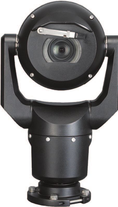
Abbildung 3.1: Typische Konfiguration mit MIC-ALM-WAS-24
1 MIC7000 Kamera 6 24-VAC-Netzteil, 1 A,
50/60 Hz (user-supplied)
Bosch Security Systems 2019-12 | 3.0 | F.01U.382.77710 de | Produktübersicht MIC Alarm-Washer Box
2 MIC Klappbarer DCA- 7 Waschanlagenpumpe
Adapter (MIC-DCA-Hx) (Zubehör)
3 RS-485-Kabel, 3-adrig 8 Schnittstellenkabel für
(user-supplied) Waschanlagensteuerung
(user-supplied)
4 MIC-ALM-WAS-24 Gehäuse 9 Alarmeingang/-ausgang-
Schnittstellenkabel (user-
supplied)
5 Schnittstellenkabel für 10 Überwachter Schalter für
24 VAC (user-supplied) für Sabotagealarm (user-
MIC-ALM-WAS-24 supplied)
2019-12 | 3.0 | F.01U.382.777 Bosch Security SystemsMIC Alarm-Washer Box Technische Daten | de 11
4 Technische Daten
Elektrische Daten
Eingangsspannung 24 VAC ±10 %, 50/60 Hz
Stromverbrauch 1,5 W
Benutzeranschlüsse
Stromversorgung 24 VAC
Alarmeingang 4 potenzialfreie Kontakte (Schließer/
Öffner wählbar)
2 überwachte
Manipulationsalarmeingänge,
Terminierung mit 2,2 kOhm
Abschlusswiderstand
Alarmausgang 3 Open-Collector-Ausgänge, 32 VDC,
150 mA
Relaisausgang 1 potenzialfreier Relaiskontakt,
24 VAC/VDC, 5 A (für
Waschanlagenpumpe)
Alarm/Daten 3-adrige Verbindung, RS-485 (an
externe Alarm-/Waschanlagen-
Zubehöreinheit), bis zu 100 m
Kabelspezifikationen
Anschluss Kabelspezifikation Maximale
Entfernung
Stromversorgung,
3-adrig 0,2-0,5 mm²/ 15 m bei
AWG 24-20 0,2 mm²/
Wasch-
AWG 24
anlagenausgang,
2-adrig
Bosch Security Systems 2019-12 | 3.0 | F.01U.382.77712 de | Technische Daten MIC Alarm-Washer Box
Anschluss Kabelspezifikation Maximale
Entfernung
120 m bei
0,5 mm²/
AWG 20
RS-485,
3-adrig, abgeschirmt 0,08-0,2 mm²/ 100 m bei
AWG 28-24 0,08 mm²/
Alarme,
AWG 28
mehradrig,
abgeschirmt
Empfehlungen zu den Kabeln
Der Kabelmantel des gewählten Kabels sollte für den Einsatz im
Freien geeignet sein (UV- und wetterbeständig, einsetzbar im
Temperaturbereich von -40 bis +60 °C).
Empfohlener Kabeldurchmesset 6-10 mm/AWG 28-24
Abisolierlänge ca. 7 mm
2019-12 | 3.0 | F.01U.382.777 Bosch Security SystemsMIC Alarm-Washer Box MIC-ALM-WAS-24-Layout | de 13
5 MIC-ALM-WAS-24-Layout
Die folgende Abbildung zeigt das Layout der MIC-ALM-WAS-24
mit der Platine und vier (4) installierten Kabelverschraubungen.
Hinweis: Bei Nummer 14 handelt es sich um die zusätzliche
M16-Kabelverschraubung anstelle des M16-Stopfens (der
werkseitig am Gehäuse eingesetzt ist).
Bosch Security Systems 2019-12 | 3.0 | F.01U.382.77714 de | MIC-ALM-WAS-24-Layout MIC Alarm-Washer Box 2019-12 | 3.0 | F.01U.382.777 Bosch Security Systems
MIC Alarm-Washer Box                                MIC-ALM-WAS-24-Layout | de      15

                  1 Loch für Deckelschraube (insgesamt vier [4])

                  2 Loch für Befestigungsschraube (insgesamt vier [4])

                  3 Kabelverschraubung M16 für das 24-VAC-
                     Stromversorgungskabel

                  4 Klemmenleiste (mit 3 Anschlüssen, beschriftet mit P300)
                     für das 24-VAC-Stromversorgungskabel

                  5 [nicht verwendet]

                  6 Klemmenleiste (mit 12 Anschlüssen, beschriftet mit
                     P101) für Alarmverbindungen

                  7 Alarm-LEDs (beschriftet mit A01, A02, A03, A11, A12,
                     A13, A14)

                  8 Klemmenleiste (mit 3 Anschlüssen, beschriftet mit P200)
                     für die RS-485-Verbindung

                  9 Kabelverschraubung M16 für die RS-485-Verbindung mit
                     der Kamera

                10 Klemmenleiste (mit 2 Anschlüssen, beschriftet mit P100)
                     für den Anschluss der Waschanlage

                11 Drucktaster (rot; beschriftet mit PUMP ON) zum
                     Aktivieren/Testen der Waschanlage

                12 Kabelverschraubung M16 für die Verbindung mit der
                     Waschanlage

                13 LED zur Anzeige der Waschanlagenaktivität

                14 Kabelverschraubung M16 für Alarmeingangs-/-
                     ausgangsverbindungen (im Lieferumfang enthalten,
                     jedoch nicht vorinstalliert)

                15 LED zum Anzeigen der Stromversorgung

Bosch Security Systems                                     2019-12 | 3.0 | F.01U.382.777
16 de | MIC-ALM-WAS-24-Layout MIC Alarm-Washer Box
16 LED (beschriftet mit ACTIVITY) zum Anzeigen von
Datenübertragung zwischen der MIC-ALM-WAS-24 und
der Kamera
2019-12 | 3.0 | F.01U.382.777 Bosch Security SystemsMIC Alarm-Washer Box Installation | de 17
6 Installation
Vorsicht!
Die Installation muss von einem qualifizierten
Wartungstechniker vorgenommen werden und den Vorschriften
gemäß ANSI/NFPA 70 (National Electrical Code® (NEC)), dem
! Canadian Electrical Code, Teil I (auch als CE-Code oder CSA
C22.1 bezeichnet) sowie allen örtlich geltenden Vorschriften
entsprechen. Bosch Security Systems haftet nicht für Schäden
oder Verluste, die auf falsche oder nicht ordnungsgemäße
Installation zurückzuführen sind.
Hinweis!
Um die Anforderungen an Netzspannungseinbrüche und
i Netzspannungsunterbrechungen gemäß Alarmstandard
EN 50130-4 erfüllen zu können, sind Zusatzgeräte (zum Beispiel
USV) erforderlich. Gemäß der auf dem Datenblatt angegebenen
Leistungsstufe muss die Umschaltzeit der USV 2 bis 6 ms und
die Speicherlaufzeit mehr als 5 Sekunden betragen.
Hinweis!
i Um die IP-Schutzart des Gehäuses zu erhalten, installieren Sie
nur Kabelverschraubungen mit derselben Schutzart. Beachten
Sie dazu die Installationsanweisungen des betreffenden Teils.
Hinweis: Die in den folgenden Installationsschritten
angegebenen Elementnummern beziehen sich auf die
Nummerierung im MIC-ALM-WAS-24-Layout.
Zur Installation der MIC-ALM-WAS-24 Befolgen Sie diese
Anweisungen.:
1. Wählen Sie einen sicheren Installationsort für das Gerät.
Idealerweise sollte der Ort so gewählt werden, dass das Gerät
weder bewusst noch unbeabsichtigt in seiner Funktion gestört
werden kann und dass die Umgebungsbedingungen den
Spezifikationen entsprechen.
Bosch Security Systems 2019-12 | 3.0 | F.01U.382.77718 de | Installation MIC Alarm-Washer Box
Um eine maximale EMV-Störfestigkeit zu erzielen, installieren Sie
das Gerät in einem für die Umgebung geeigneten Geräteschrank,
der vorschriftsmäßig geerdet ist.
2. Entfernen Sie den Deckel.
– Lösen Sie die vier (4) M4-Schrauben und nehmen Sie den
Deckel des Gehäuses (Element 1) ab.
3. Befestigen Sie das Gerät ggf. auf einer stabilen Oberfläche.
– Suchen Sie die vier (4) Befestigungslöcher (Element 2).
– Bohren Sie vier (4) Löcher in die Montagefläche (siehe
Abmessungen in der folgenden Abbildung).
– Befestigen Sie das Gehäuse mit den M4-Schrauben (Nr. 8)
und Unterlegscheiben (nicht mitgeliefert) an der
Montagefläche.
(3.54 in.)
90 mm
188 mm
(7.40 in.)
Abbildung 6.1: Abmessungen, Befestigungslöcher für MIC-ALM-WAS-24
4. Installationsanweisungen finden Sie auf dem Deckel-Etikett.
– Installationsanweisungen finden Sie in das Etikett auf der
Innenseite den Gehäusedeckel.
2019-12 | 3.0 | F.01U.382.777 Bosch Security SystemsMIC Alarm-Washer Box Installation | de 19
5. Schließen Sie das RS-485-Kabel der Kamera an das Gerät
an.
– Bereiten Sie das Kabel nach Bedarf vor.
– Wählen Sie je nach Installationsort die geeignetste
Kabelverschraubung aus. Empfohlen wird die Verwendung
von Element 9.
– Führen Sie das Kabel durch die Kabelverschraubung in das
Gehäuse.
– Schließen Sie es gemäß den Angaben in der folgenden
Tabelle an die Klemmenleiste P200 (Element 8) an.
Kontakt Beschreibung/Funktion
1 Daten-
2 Masse
3 Daten+
– Überprüfen Sie abschließend die Verbindungen.
6. Schließen Sie das Stromversorgungskabel an.
– Bereiten Sie das Kabel nach Bedarf vor.
– Wählen Sie je nach Installationsort die geeignetste
Kabelverschraubung aus. Empfohlen wird die Verwendung
von Element 3.
– Führen Sie das Kabel durch die Kabelverschraubung in das
Gehäuse.
– Schließen Sie es gemäß den Angaben in der folgenden
Tabelle an die Klemmenleiste P300 (Element 4) an.
Kontakt Beschreibung/Funktion
1 Phase
2 Gehäuseerdung
3 Nullleiter
– Überprüfen Sie abschließend die Verbindungen.
7. Schließen Sie ggf. die Alarmein- und -ausgänge an.
– Bereiten Sie das Kabel nach Bedarf vor.
Bosch Security Systems 2019-12 | 3.0 | F.01U.382.77720 de | Installation MIC Alarm-Washer Box
– Wählen Sie je nach Installationsort die geeignetste
Kabelverschraubung aus. Empfohlen wird die Verwendung
von Element 14.
– Bei Verwendung des Elements 14 entfernen Sie den M16-
Stopfen und setzen Sie an dieser Stelle die zusätzliche
Kabelverschraubung (im Lieferumfang enthalten) für die
Alarmeingangs-/-ausgangsschnittstelle ein.
– Führen Sie das Kabel durch die Kabelverschraubung in das
Gehäuse.
– Schließen Sie die Alarmeingänge (für externe Geräte wie
Türkontakte oder Sensoren) und Alarmausgänge (zum
Schalten von externen Geräten wie Strahler, Alarmsirenen
oder anderen Alarmeinheiten) an die Klemmenleiste P101
(Element 6) gemäß den Angaben in der folgenden Tabelle
an.
Hinweis 1: Die Kontakte der Klemmenleiste P101 sind von
rechts nach links nummeriert.
Hinweis 2: Die MASSE-Anschlüsse können mit einem
beliebigen Alarmeingang oder -ausgang verbunden werden.
Kontakt Beschreibung/Funktion
1 Alarmeingang 1
2 Alarmeingang 2
3 Alarmeingang 3
4 Alarmeingang 4
5 Masse
6 Alarmausgang 1
7 Alarmausgang 2
8 Alarmausgang 3
9 Masse
10 Manipulationsalarm 1
2019-12 | 3.0 | F.01U.382.777 Bosch Security SystemsMIC Alarm-Washer Box Installation | de 21
Kontakt Beschreibung/Funktion
11 Manipulationsalarm 2
12 Masse
– Überprüfen Sie abschließend die Verbindungen.
– Bei der Verwendung von Manipulationsalarmeingängen
schließen Sie einen Abschlusswiderstand von 2,2 kOhm in
der Nähe des Alarmkontakts an.
8. Schließen Sie ggf. die Steuerung der Waschanlagenpumpe
an.
– Bereiten Sie das Kabel nach Bedarf vor.
– Wählen Sie je nach Installationsort die geeignetste
Kabelverschraubung aus. Empfohlen wird die Verwendung
von Element 12.
– Führen Sie das Kabel durch die Kabelverschraubung in das
Gehäuse.
– Schließen Sie das Kabel gemäß den Angaben in der
folgenden Tabelle an der Klemmenleiste P100 (Element 10)
an.
Kontakt Beschreibung/Funktion
1 Schließer-Relaiskontakt
2 Relais-Bezugspotenzial
– Überprüfen Sie abschließend die Verbindungen.
9. Prüfen Sie die Stromversorgung.
– Schalten Sie das Gerät ein.
– Testen Sie ggf. die Funktion der Waschanlage. Drücken Sie
dazu den roten Drucktaster mit der Beschriftung „PUMP
ON“ auf der Platine (Element 11).
Die mit „WASHER“ beschriftete LED (Element 13) leuchtet
als Antwort auf Telemetriebefehle zum Einschalten der
Waschanlage. Die Software der Kamera verhindert, dass die
Waschanlage länger als 10 Sekunden durchgehend läuft,
um ein Leerlaufen der Waschanlagenflasche zu verhindern.
Bosch Security Systems 2019-12 | 3.0 | F.01U.382.77722 de | Installation MIC Alarm-Washer Box
In der folgenden Tabelle sind die Zustände der LEDs auf der
Platine (PCBA) bei ordnungsgemäßer Funktion des Gerätes
aufgeführt.
LED Anzeige Beschreibung
Rote LED EIN Gerät wird mit Strom versorgt
Grüne LEDs Blinken Aktive Alarme
Gelbe LED Blinkt RS-485-Datenübertragung
aktiv
10. Schließen Sie die Montage ab.
– Setzen Sie den Gehäusedeckel wieder auf.
– Ziehen Sie die vier (4) Schrauben des Deckels mit 1–
1,5 Nm fest, um sicherzustellen, dass das Gehäuse
wasserdicht ist.
– Befestigen Sie ggf. die Schraubenabdeckungen auf den
Schrauben, um Manipulationen am Gehäuse zu verhindern.
2019-12 | 3.0 | F.01U.382.777 Bosch Security SystemsMIC Alarm-Washer Box Problembehandlung | de 23
7 Problembehandlung
In der folgenden Tabelle sind die Zustände der LEDs auf der
Platine (PCBA) bei nicht ordnungsgemäßer Funktion des
Gerätes aufgeführt.
LED- LED- Beschreibung Auflösung
Farbe Anzeige
Rote AUS Die Strom- Stellen Sie die
LED versorgung ist Strom-versorgung
ausgeschaltet oder wieder her.
das 24-VAC-Kabel Korrigieren Sie
wurde mit der die Polarität.
falschen Polarität
angeschlossen.
Gelbe AUS Kein Prüfen Sie die
LED Datenaustausch Polarität der
zwischen der MIC- Verbindung mit
ALM-WAS-24 und dem RS-485-
der Kamera. Kabel.
Bosch Security Systems 2019-12 | 3.0 | F.01U.382.77724 en | Safety MIC Alarm-Washer Box
1 Safety
1.1 Important Safety Instructions
Read, follow, and retain for future reference all of the following
safety instructions. Follow all warnings before operating the
unit.
1. Clean only with a dry cloth. Do not use liquid cleaners or
aerosol cleaners.
2. Do not install unit near any heat sources such as radiators,
heaters, stoves, or other equipment (including amplifiers)
that produce heat.
3. Never spill liquid of any kind on the unit.
4. Take precautions to protect the unit from power and
lightning surges.
5. Adjust only those controls specified in the operating
instructions.
6. Operate the unit only from the type of power source
indicated on the label.
7. Unless qualified, do not attempt to service a damaged unit
yourself. Refer all servicing to qualified service personnel.
8. Install in accordance with the manufacturer's instructions in
accordance with applicable local codes.
9. Use only attachments/accessories specified by the
manufacturer.
Notice!
To meet the Mains Supply Voltage Dips and Short Interruptions
i requirements per EN 50130-4 Alarm Standard, ancillary
equipment (for example, UPS) is necessary. The UPS must have
a Transfer time between 2-6 ms and Backup Runtime of greater
than 5 seconds for the power level as specified on the product
data sheet.
2019-12 | 3.0 | F.01U.382.777 Bosch Security SystemsMIC Alarm-Washer Box Unpacking | en 25
2 Unpacking
– This equipment should be unpacked and handled with care.
Check the exterior of the packaging for visible damage. If
an item appears to have been damaged in shipment, notify
the shipper immediately.
– Verify that all the parts listed in the Parts List below are
included. If any items are missing, notify your Bosch
Security Systems Sales or Customer Service
Representative.
– Do not use this product if any component appears to be
damaged. Please contact Bosch Security Systems in the
event of damaged goods.
– The original packing carton is the safest container in which
to transport the unit and must be used if returning the unit
for service. Save it for possible future use.
2.1 Parts List
Each device ships with the following parts:
– Enclosure with three (3) watertight M16 cable glands and
one (1) M16 blanking plug installed
– One (1) watertight M16 cable gland, uninstalled
– Four (4) Pozidriv screws for lid
– Four (4) screw caps to cover the lid screws
– Installation Manual
2.2 Additional Parts/Tools Required
Installers must provide the following items to complete
installation of a MIC-ALM-WAS-24:
– Power source, 24 VAC, 50/60 Hz, 1A
– #2 Phillips-head or Pozidriv screwdriver for the lid screws
– Four (4) M4 (#8) mounting screws and washers
– Screwdriver for the mounting screws
Bosch Security Systems 2019-12 | 3.0 | F.01U.382.77726 en | Product overview MIC Alarm-Washer Box
3 Product overview
The MIC Alarm/Washer Interface (MIC-ALM-WAS-24) provides
the following features:
– user connections for alarms inputs
– user connections for alarm outputs
– user connections for a washer (used to spray water or
cleaner on the viewing window of the camera) that is
connected to the interface
– a push button on the PCBA to allow users to activate/test
the washer
The 3-wire RS-485 cable from the base of the camera feeds
through the watertight cable gland in the enclosure and
connects to terminal block P200 on the PCBA.
The device requires a 24 VAC, 50/60 Hz, 1A power source (user-
supplied). All input/output connections (for external
connections) have surge protection against ESD, RFI and voltage
transients.
The enclosure, rated to IP67, is made of impact-resistant
polycarbonate to withstand exposure to wet environments.
(3.11 in.)
79 mm
m
in.)
0m
200
mm
72
12
(7.87
(4.
in.)
2019-12 | 3.0 | F.01U.382.777 Bosch Security SystemsMIC Alarm-Washer Box Product overview | en 27
Figure 3.1: Typical configuration with MIC-ALM-WAS-24
1 MIC7000 camera 6 24 VAC Power pack, 1A,
50/60 Hz (user-supplied)
2 MIC Hinged DCA (MIC- 7 Washer pump accessory
DCA-Hx)
3 RS-485 cable, 3-conductor 8 Interface cable for washer
(user-supplied) control (user-supplied)
4 MIC-ALM-WAS-24 9 Alarm input / output
enclosure interface cables (user-
supplied)
5 Interface cable for 24 VAC 10 Monitored switch for
(user-supplied) for MIC- Tamper Alarm (user-
ALM-WAS-24 supplied)
Bosch Security Systems 2019-12 | 3.0 | F.01U.382.77728 en | Technical Data MIC Alarm-Washer Box
4 Technical Data
Electrical
Input voltage 24 VAC ± 10%, 50/60 Hz
Power consumption 1.5 W
User Connections
Power 24 VAC
Alarm Input 4 normal dry contacts (selectable
N.O./N.C.)
2 monitored tamper alarm inputs,
2.2K ohm end-of-line termination
Alarm Output 3 open collector outputs, 32 VDC,
150 mA
Relay Output 1 dry contact relay, 24VAC/VDC, 5 A
(for washer pump)
Alarm/Data 3-wire RS-485 (to external alarm/
washer accessory unit) up to 100 m
Cable Requirements
Connection Cable Gage Maximum Distance
Power,
3-conductor 0.2 mm² - 0.5 15 m (50 ft) with 0.2
mm² / mm² / AWG 24
Washer output,
AWG 24 – 20 120 m (400 ft) with 0.5
2-conductor
mm² / AWG 20
RS-485,
3-conductor 0.08 mm² - 0.2 100 m (330 ft) with 0.08
shielded mm² / mm² / AWG 28
AWG 28 - 24
2019-12 | 3.0 | F.01U.382.777 Bosch Security SystemsMIC Alarm-Washer Box Technical Data | en 29
Connection Cable Gage Maximum Distance
Alarms,
Multi-conductor
shielded
Cable Recommendations
The jacket of each selected cable should be suitable for outdoor
use (UV-resistant, weather-resistant, able to meet an operating
temperature range of -40 to +60 °C (-40 to +140 °F)).
Recommended cable diameter 6 - 10 mm (¼” – 3/8”) /
AWG 28 - 24
Stripping length 7 mm (0.25 in.
approximately)
Bosch Security Systems 2019-12 | 3.0 | F.01U.382.77730 en | MIC-ALM-WAS-24 Layout MIC Alarm-Washer Box
5 MIC-ALM-WAS-24 Layout
The figure below illustrates the layout of the MIC-ALM-WAS-24,
with the Printed Circuit Board Assembly (PCBA) and four (4)
cable glands installed. Note: item 14 shows the extra M16 cable
gland in place of the M16 plug (which is factory-installed in the
enclosure).
2019-12 | 3.0 | F.01U.382.777 Bosch Security SystemsMIC Alarm-Washer Box MIC-ALM-WAS-24 Layout | en 31 Bosch Security Systems 2019-12 | 3.0 | F.01U.382.777
32    en | MIC-ALM-WAS-24 Layout                            MIC Alarm-Washer Box

                   1 Hole for lid screw [four (4) total]

                   2 Hole for mounting screw [four (4) total]

                   3 Cable gland, size M16, intended for 24 VAC power cable

                   4 Terminal block (3-pin, labeled P300 / Voltage In) for 24
                      VAC power cable

                   5 [Not used]

                   6 Terminal block (12-pin, labeled P101) for alarm
                      connections

                   7 Alarm LEDs (labeled AO1, AO2, AO3, AI1, AI2, AI3, AI4)

                   8 Terminal block (3-pin, labeled P200) for RS-485
                      connections

                   9 Cable gland, size M16, intended for RS-485 connections
                      from camera

                 10 Terminal block (2-pin, labeled P100) for connections to
                      washer

                 11 Push button (red; labeled PUMP ON) to activate/test the
                      washer

                 12 Cable gland, size M16, intended for connections to
                      washer

                 13 LED (labeled Washer LED) to indicate activity of washer

                 14 Cable gland, size M16, intended for alarm input/output
                      connections [Supplied but not factory-installed]

                 15 LED to indicate power (Red indicates power on)

                 16 LED (labeled ACTIVITY) to indicate communications
                      between the MIC-ALM-WAS-24 and the camera

2019-12 | 3.0 | F.01U.382.777                                Bosch Security Systems
MIC Alarm-Washer Box Installation | en 33
6 Installation
Caution!
Installation must be made by qualified personnel and conform
to ANSI/NFPA 70 (the National Electrical Code® (NEC)),
! Canadian Electrical Code, Part I (also called CE Code or CSA
C22.1), and all applicable local codes. Bosch Security Systems,
Inc. accepts no liability for any damages or losses caused by
incorrect or improper installation.
Notice!
To meet the Mains Supply Voltage Dips and Short Interruptions
i requirements per EN 50130-4 Alarm Standard, ancillary
equipment (for example, UPS) is necessary. The UPS must have
a Transfer time between 2-6 ms and Backup Runtime of greater
than 5 seconds for the power level as specified on the product
data sheet.
Notice!
To maintain the IP (protection) rating of the enclosure, install
i only listed or recognized glands with the same environmental
rating as the enclosure according to the installation instructions
of the gland.
Note: All item numbers referenced in the following steps refer to
the MIC-ALM-WAS-24 Layout.
To install the MIC-ALM-WAS-24, follow these steps:
1. Select a secure installation location for the device. Ideally,
this is a location where the device cannot be interfered with
intentionally or accidentally and that will ensure that
environmental conditions are within the rated specifications.
To provide maximum protection against EMC interference,
install the device inside an environmentally suitable equipment
cabinet that has a good connection to earth ground.
Bosch Security Systems 2019-12 | 3.0 | F.01U.382.77734 en | Installation MIC Alarm-Washer Box
2. Remove the lid.
– Loosen the four (4) M4 screws and remove the lid of the
enclosure (item 1).
3. Mount the device to a stable surface, if desired.
– Locate the four (4) mounting holes (item 2).
– If applicable, drill four (4) holes in the mounting surface,
using the figure below as reference.
– Secure the enclosure to the mounting surface using M4
(#8) screws and washers (not supplied).
(3.54 in.)
90 mm
188 mm
(7.40 in.)
Figure 6.1: Dimensions, mounting holes, MIC-ALM-WAS-24
4. Refer to installation information on the lid label.
– Refer to the label on the inside of the lid of the enclosure
for important installation information.
5. Connect the RS-485 communication cable from the camera
to the device.
– Prepare the cable as needed.
– Select the cable gland in the most suitable location based
on installation conditions. Item 9 is recommended.
– Feed the cable through the cable gland into the enclosure.
2019-12 | 3.0 | F.01U.382.777 Bosch Security SystemsMIC Alarm-Washer Box Installation | en 35
– Make the connections to terminal block P200 (item 8)
according to the table below.
Pin Description / Function
1 Data-
2 Ground
3 Data+
– Check that the connections are secure.
6. Connect the power cable.
– Prepare the cable as needed.
– Select the cable gland in the most suitable location based
on installation conditions. Item 3 is recommended.
– Feed the cable through the cable gland into the enclosure.
– Make the connections to terminal block P300 (item 4)
according to the table below.
Pin Description / Function
1 24VAC
2 Chassis Ground
3 24VAC
– Check that the connections are secure.
7. Connect Alarm inputs and outputs, if desired.
– Prepare the cable as needed.
– Select the cable gland in the most suitable location based
on installation conditions. Item 14 is recommended.
– If you selected the gland location identified as item 14,
remove the M16 plug; insert in its place the extra cable
gland (supplied) for the alarm input / output interface.
– Feed the cable through the cable gland into the enclosure.
– Make the connections for the alarm inputs (for external
devices such as door contacts or sensors) and alarm
outputs (for switching external units such as lamps, alarm
sirens, or other alarm units) to terminal block P101 (item 6)
Bosch Security Systems 2019-12 | 3.0 | F.01U.382.77736 en | Installation MIC Alarm-Washer Box
according to the table below.
Note 1: Pins are numbered from right to left on terminal
block P101.
Note 2: Any of the GND terminals can be used with any
alarm input/output.
Pin Description / Function LED
1 Alarm Input 3 AI1
2 Alarm Input 4 AI2
3 Alarm Input 5 AI3
4 Alarm Input 6 AI4
5 Ground
6 Alarm Output 1 AO1
7 Alarm Output 2 AO2
8 Alarm Output 3 AO3
9 Ground
10 Tamper Alarm Input 1
11 Tamper Alarm Input 2
12 Ground
– Check that the connections are secure.
– If tamper alarm inputs are used, attach a 2.2 K ohm end-of-
line termination near the alarm contact.
8. Connect the washer pump drive, if desired.
– Prepare the cable as needed.
– Select the cable gland in the most suitable location based
on installation conditions. Item 12 is recommended.
– Feed the cable through the cable gland into the enclosure.
– Make the connections to terminal block P100 (item 10)
according to the table below.
2019-12 | 3.0 | F.01U.382.777 Bosch Security SystemsMIC Alarm-Washer Box Installation | en 37
Pin Description / Function
1 Relay Normally Open
2 Relay Common
– Check that the connections are secure.
9. Verify power to the device.
– Apply power to the device.
– If desired, test the washer by pushing the red button
labeled “PUMP ON” on the PCBA (item 11).
The LED labeled “WASHER” on the PCBA (item 13)
illuminates in response to telemetry commands to turn on
the washer. Note that the software in the camera prevents
the washer from running more than 10 seconds
continuously to prevent emptying the washer bottle.
The table below identifies the behavior of the LEDs on the PCBA
when the device is working as expected.
LED Indicator Description
Red LED ON Power ON
Green LEDs Blinking Alarms active
Yellow LED Blinking RS-485 communications
active
10. Complete installation.
– Re-attach the enclosure lid.
– Tighten the four (4) lid screws to 1.5 N m (9 - 13 in. lb) to
ensure that the enclosure is watertight.
– If desired, slide the screw caps over the lid screws to
protect the enclosure from tampering.
Bosch Security Systems 2019-12 | 3.0 | F.01U.382.77738 en | Troubleshooting MIC Alarm-Washer Box
7 Troubleshooting
The table below identifies the behavior of the LEDs on the PCBA
when the device is not working as expected.
LED LED Description Resolution
Color indicator
Red LED OFF Power is OFF or Reconnect
incorrect polarity is power to the
applied to the 24 device.
VAC input connector. Correct polarity.
Yellow OFF Communications Verify RS-485
LED between the MIC- wire polarity.
ALM-WAS-24 and the
camera are not
available.
2019-12 | 3.0 | F.01U.382.777 Bosch Security SystemsMIC Alarm-Washer Box Seguridad | es 39
1 Seguridad
1.1 Instrucciones de seguridad importantes
Lea y siga las instrucciones de seguridad que se detallan a
continuación, y guárdelas para poder consultarlas en el futuro.
Preste atención a todas las advertencias antes de utilizar la
unidad.
1. Límpiela sólo con un paño seco. No utilice limpiadores
líquidos ni aerosoles.
2. La unidad no se debe instalar cerca de fuentes de calor
como radiadores, calefactores, estufas u otros equipos
(incluidos amplificadores) que produzcan calor.
3. No derrame líquido de ningún tipo en la unidad.
4. Tome las precauciones necesarias para proteger la unidad
de tormentas eléctricas y subidas de tensión.
5. Ajuste sólo los controles especificados en las instrucciones
de funcionamiento.
6. Utilice la unidad sólo con el tipo de fuente de alimentación
indicado en la etiqueta.
7. A menos que esté cualificado para ello, no intente reparar
una unidad dañada. Todas las reparaciones deben correr a
cargo de personal de servicio cualificado.
8. Instale esta unidad de acuerdo con las instrucciones del
fabricante y conforme a las normas aplicables en su país.
9. Utilice sólo conexiones y accesorios especificados por el
fabricante.
Aviso!
Para cumplir los requisitos de la norma para alarmas EN
50130-4 sobre fluctuaciones y caídas de la tensión eléctrica, se
i necesita equipo auxiliar, como una fuente de alimentación
ininterrumpida (SAI). La SAI debe tener un tiempo de
transferencia entre 2-6 ms y un tiempo para ejecución de
copias de seguridad superior a 5 segundos para el nivel de
potencia especificado en la hoja de datos del producto.
Bosch Security Systems 2019-12 | 3.0 | F.01U.382.77740 es | Desembalaje MIC Alarm-Washer Box
2 Desembalaje
– Desembale y manipule el equipo con cuidado. Compruebe
el exterior del embalaje por si observa daños visibles. Si
parece que algún componente se ha dañado durante el
transporte, informe al transportista inmediatamente.
– Compruebe que se hayan incluido todas las piezas que se
mencionan en la lista de piezas que aparece a continuación.
Si falta algún artículo, comuníquelo al representante de
ventas o al representante de atención al cliente de Bosch
Security Systems.
– No utilice este producto si algún componente parece estar
dañado. En caso de que algún artículo esté dañado,
póngase en contacto con Bosch Security Systems.
– La caja de cartón original es el embalaje más seguro para
transportar la unidad y deberá utilizarse para su devolución
en caso de que deba repararse. Guárdela, ya que es posible
que la necesite en el futuro.
2.1 Lista de piezas
Cada dispositivo incluye las siguientes piezas:
– Carcasa con tres (3) prensaestopas M16 estancas y una (1)
tapa M16 instalados
– Una (1) prensaestopa M16 estanca sin instalar
– Cuatro (4) tornillos Pozidriv para la tapa
– Cuatro (4) embellecedores para los tornillos de la tapa
– Manual de instalación
2.2 Piezas adicionales y herramientas
necesarias
Los instaladores deben proporcionar los siguientes elementos
para completar la instalación de una unidad MIC-ALM-WAS-24.
– Fuente de alimentación de 24 V CA, 50/60 Hz, 1 A.
– Destornillador de cabeza Phillips o Pozidriv nº 2 para los
tornillos de la tapa.
– Cuatro (4) tornillos de montaje M4 (nº 8) con arandelas.
2019-12 | 3.0 | F.01U.382.777 Bosch Security SystemsMIC Alarm-Washer Box Desembalaje | es 41
– Destornillador para los tornillos de montaje.
Bosch Security Systems 2019-12 | 3.0 | F.01U.382.77742 es | Descripción del producto MIC Alarm-Washer Box
3 Descripción del producto
La unidad de interfaz de alarmas/limpieza MIC (MIC-ALM-
WAS-24) ofrece las siguientes funciones:
– Conexiones de usuario para entradas de alarma
– Conexiones de usuario para salidas de alarma
– Conexiones de usuario para un lavador (usado para
pulverizar agua o un limpiador en la ventana de
visualización de la cámara) que se conecta a la interfaz
– Pulsador en la PCBA (tajeta de circuito impreso) que
permite a los usuarios activar o probar el lavador
La alimentación del cable RS-485 de 3 hilos de la base de la
cámara se realiza a través de la prensaestopa estanca de la
carcasa y se conecta al bloque de terminales P200 en la PCB.
El dispositivo requiere una fuente de alimentación de 24 V CA,
50/60 Hz, 1 A (suministrada por el usuario). Todas las
conexiones de entrada/salida (para conexiones externas) tienen
protección contra las subidas de tensión por descargas de
electricidad estática (ESD), interferencias por radiofrecuencia
(RFI) y sobretensión transitoria.
La carcasa, compatible con IP67, está fabricada en
policarbonato a prueba de impactos para soportar la exposición
a entornos húmedos.
2019-12 | 3.0 | F.01U.382.777 Bosch Security SystemsMIC Alarm-Washer Box Descripción del producto | es 43
(3.11 in.)
79 mm
m
in.)
0m
200
mm
72
12
(7.87
(4.
in.)
Figura 3.1: Configuración habitual con MIC-ALM-WAS-24
1 Cámara MIC7000 6 Paquete de alimentación
de 24 VCA, 1 A y 50/60 Hz
(user-supplied)
Bosch Security Systems 2019-12 | 3.0 | F.01U.382.77744 es | Descripción del producto MIC Alarm-Washer Box
2 MIC con montura DCA con 7 Accesorio de la bomba del
bisagras (MIC-DCA-Hx) lavador
3 Cable RS-485 de 3 8 Cable de interfaz para
conductores (user- controlar el lavador (user-
supplied) supplied)
4 Carcasa de MIC-ALM- 9 Cables de interfaz de
WAS-24 entrada/salida de alarma
(user-supplied)
5 Cable de interfaz de 10 Contacto controlado de la
24 VCA (user-supplied) alarma de sabotaje (user-
para MIC-ALM-WAS-24 supplied)
2019-12 | 3.0 | F.01U.382.777 Bosch Security SystemsMIC Alarm-Washer Box Datos técnicos | es 45
4 Datos técnicos
Especificaciones eléctricas
Tensión de entrada 24 VCA ± 10 %, 50/60 Hz
Consumo de energía 1,5 W
Conexiones de usuario
Alimentación 24 VCA
Entrada de alarma 4 contactos secos normales (N.A./N.C.
seleccionable)
2 entradas de alarma antisabotaje
monitorizadas, terminación final de
2200 ohmios
Salida de alarma 3 salidas de colector abierto, 32 VCC,
150 mA
Salida relé 1 relé de contacto seco, 24 VCA/VCC,
5 A (para la bomba del lavador)
Alarma/datos RS-485 de 3 hilos (para conexión a la
unidad del accesorio lavador/alarma
externa) de hasta 100 m
Requisitos del cable
Conexión Calibre del Distancia máxima
cable
Alimentación,
3 conductores 0,2 mm² - 15 m (50 pies) con
0,5 mm²/ 0,2 mm²/AWG 24
Salida del lavador,
AWG 24 - 20 120 m (400 pies) con
2 conductores
0,5 mm²/AWG 20
RS-485,
blindado de 3 100 m (330 pies) con
conductores 0,08 mm²/AWG 28
Bosch Security Systems 2019-12 | 3.0 | F.01U.382.77746 es | Datos técnicos MIC Alarm-Washer Box
Conexión Calibre del Distancia máxima
cable
Alarmas, 0,08 mm² -
blindado 0,2 mm²/
multiconductor AWG 28 - 24
Recomendaciones del cableado
El revestimiento de los cables seleccionados debe ser adecuado
para su uso en exteriores (resistente a rayos ultravioleta,
resistente a la intemperie, capaz de ajustarse a un rango de
temperatura de funcionamiento de -40 a +60 °C [de -40 a
+140 °F]).
Diámetro de cable recomendado De 6 a 10 mm (¼” - 3/8”)/
AWG 28 - 24
Longitud de pelado 7 mm (0,25 pulg.
aproximadamente)
2019-12 | 3.0 | F.01U.382.777 Bosch Security SystemsMIC Alarm-Washer Box Disposición de MIC-ALM-WAS-24 | es 47
5 Disposición de MIC-ALM-WAS-24
En la figura siguiente se muestra la disposición de la unidad
MIC-ALM-WAS-24, con el ensamblaje de la tarjeta de circuitos
impresa (PCBA) y cuatro (4) prensaestopas instaladas. Nota: el
elemento 14 muestra la prensaestopa M16 adicional en lugar del
tapón M16 (instalado de serie en la carcasa).
Bosch Security Systems 2019-12 | 3.0 | F.01U.382.77748 es | Disposición de MIC-ALM-WAS-24 MIC Alarm-Washer Box 2019-12 | 3.0 | F.01U.382.777 Bosch Security Systems
MIC Alarm-Washer Box                      Disposición de MIC-ALM-WAS-24 | es      49

                  1 Orificio para tornillo de la tapa [cuatro (4) en total]

                  2 Orificio para tornillo de montaje [cuatro (4) en total]

                  3 Prensaestopa, tamaño M16, para cable de alimentación
                     de 24 V CA

                  4 Bloque de terminales (3 patillas, con etiqueta P300)
                     para cable de alimentación de 24 V CA

                  5 [No se utiliza]

                  6 Bloque de terminales (12 polos, con etiqueta P101) para
                     las conexiones de alarma

                  7 LEDs de alarma (con etiquetas A01, A02, A03, A11, A12,
                     A13, A14)

                  8 Bloque de terminales (3 polos, etiqueta P200) para las
                     conexiones RS-485

                  9 Prensaestopa, tamaño M16, para las conexiones RS-485
                     de la cámara

                10 Bloque de terminales (2 polos, con etiqueta P100) para
                     las conexiones al lavador

                11 Pulsador (rojo; con etiqueta PUMP ON) para activar o
                     probar el lavador

                12 Prensaestopa, tamaño M16, para las conexiones al
                     lavador

                13 LED que indica la actividad del lavador

                14 Prensaestopa, tamaño M16, para las conexiones de
                     entrada/salida de alarma [incluida, pero no instalada de
                     serie]

                15 LED indicador de encendido

Bosch Security Systems                                   2019-12 | 3.0 | F.01U.382.777
50 es | Disposición de MIC-ALM-WAS-24 MIC Alarm-Washer Box
16 LED (con etiqueta ACTIVITY) para indicar las
comunicaciones entre la unidad MIC-ALM-WAS-24 y la
cámara
2019-12 | 3.0 | F.01U.382.777 Bosch Security SystemsMIC Alarm-Washer Box Instalación | es 51
6 Instalación
Precaución!
La instalación la debe realizar personal cualificado conforme a
la norma ANSI/NFPA 70 (National Electric Code®, NEC), el
Código Eléctrico Canadiense, parte I (también denominado
! Código CE o CSA C22.1) y todas las normas aplicables en su
país. Bosch Security Systems, Inc. no acepta responsabilidad
alguna por daños ni pérdidas ocasionados por una instalación
incorrecta o inadecuada.
Aviso!
Para cumplir los requisitos de la norma para alarmas EN
50130-4 sobre fluctuaciones y caídas de la tensión eléctrica, se
i necesita equipo auxiliar, como una fuente de alimentación
ininterrumpida (SAI). La SAI debe tener un tiempo de
transferencia entre 2-6 ms y un tiempo para ejecución de
copias de seguridad superior a 5 segundos para el nivel de
potencia especificado en la hoja de datos del producto.
Aviso!
Para mantener el índice de protección IP de la carcasa, instale
i solo prensaestopas reconocidas o catalogadas con la misma
clasificación medioambiental que la carcasa y de acuerdo con
las instrucciones de instalación de la prensaestopa.
Nota: todos los números de artículo mencionados en los pasos
siguientes hacen referencia a la disposición de la unidad MIC-
ALM-WAS-24.
Para instalar la unidad MIC-ALM-WAS-24, siga estos pasos:
1. Seleccione una ubicación de instalación segura para el
dispositivo. Lo ideal sería un lugar en el que el dispositivo no se
pueda manipular intencionada ni accidentalmente y en el que se
pueda garantizar que las condiciones ambientales se mantengan
dentro de las especificaciones indicadas.
Bosch Security Systems 2019-12 | 3.0 | F.01U.382.77752 es | Instalación MIC Alarm-Washer Box
Para ofrecer la máxima protección frente a interferencias EMC,
instale el dispositivo dentro de un compartimento adecuado
para el entorno con una buena conexión a tierra.
2. Retire la tapa.
– Afloje los cuatro (4) tornillos M4 y retire la tapa de la
carcasa (elemento 1).
3. Instale el dispositivo en una superficie estable, si lo desea.
– Localice los cuatro (4) orificios de montaje (elemento 2).
– Si procede, perfore cuatro (4) orificios en la superficie de
montaje usando la imagen siguiente como referencia.
– Fije la carcasa a la superficie de montaje con los tornillos
M4 (nº 8) y las arandelas correspondientes (no
suministrados).
(3.54 in.)
90 mm
188 mm
(7.40 in.)
Figura 6.1: Dimensiones, orificios de montaje, MIC-ALM-WAS-24
4. Consulte la información de instalación sobre la etiqueta de
tapa.
– Consulte la etiqueta sobre el interior de la tapa del recinto
para la información de instalación importante.
2019-12 | 3.0 | F.01U.382.777 Bosch Security SystemsMIC Alarm-Washer Box Instalación | es 53
5. Conecte el cable de comunicación RS-485 de la cámara al
dispositivo.
– Prepare el cable según sea necesario.
– Seleccione la prensaestopa que se encuentre en la
ubicación más adecuada según las condiciones de
instalación. Se recomienda usar el elemento 9.
– Pase el cable por la prensaestopa e introdúzcalo en la
carcasa.
– Realice las conexiones al bloque de terminales P200
(elemento 8) como se indica en la tabla siguiente.
Polo Descripción/función
1 Datos-
2 Toma de tierra
3 Datos+
– Compruebe que las conexiones son seguras.
6. Conecte el cable de alimentación.
– Prepare el cable según sea necesario.
– Seleccione la prensa que se encuentre en la ubicación más
adecuada según las condiciones de instalación. Se
recomienda usar el elemento 3.
– Pase el cable por la prensaestopa e introdúzcalo en la
carcasa.
– Realice las conexiones al bloque de terminales P300
(elemento 4) como se indica en la tabla siguiente.
Polo Descripción/función
1 Tensión de línea
2 Toma de tierra del chasis
3 Tensión neutra
– Compruebe que las conexiones son seguras.
7. Conecte las entradas y salidas de alarma, si lo desea.
– Prepare el cable según sea necesario.
Bosch Security Systems 2019-12 | 3.0 | F.01U.382.77754 es | Instalación MIC Alarm-Washer Box
– Seleccione la prensaestopa que se encuentre en la
ubicación más adecuada según las condiciones de
instalación. Se recomienda usar el elemento 14.
– Si ha seleccionado la ubicación marcada como elemento 14
para la prensaestopa, retire el tapón M16 e inserte en su
lugar la prensaestopa adicional (suministrada) para la
interfaz de entrada/salida de alarma.
– Pase el cable por la prensaestopa e introdúzcalo en la
carcasa.
– Realice las conexiones para las entradas (dispositivos
externos, como contactos de puertas o sensores) y salidas
(encendido y apagado de unidades externas, como
lámparas, sirenas de alarma u otras unidades similares) de
alarma al bloque de terminales P101 (elemento 6) como se
indica en la tabla siguiente.
Nota 1: los polos están numerados de derecha a izquierda
en el bloque de terminales P101.
Nota 2: todos los terminales GND se pueden usar con
cualquiera de las entradas/salidas de alarma.
Polo Descripción/función
1 Entrada de alarma 1
2 Entrada de alarma 2
3 Entrada de alarma 3
4 Entrada de alarma 4
5 Toma de tierra
6 Salida de alarma 1
7 Salida de alarma 2
8 Salida de alarma 3
9 Toma de tierra
10 Alarma antisabotaje 1
2019-12 | 3.0 | F.01U.382.777 Bosch Security SystemsMIC Alarm-Washer Box Instalación | es 55
Polo Descripción/función
11 Alarma antisabotaje 2
12 Toma de tierra
– Compruebe que las conexiones son seguras.
– Si se usan entradas de alarma antisabotaje, conecte una
terminación final de 2.200 ohmios cerca del contacto de la
alarma.
8. Conecte la bomba del lavador, si lo desea.
– Prepare el cable según sea necesario.
– Seleccione la prensaestopa que se encuentre en la
ubicación más adecuada según las condiciones de
instalación. Se recomienda usar el elemento 12.
– Pase el cable por la prensaestopa e introdúzcalo en la
carcasa.
– Realice las conexiones al bloque de terminales P100
(elemento 10) como se indica en la tabla siguiente.
Polo Descripción/función
1 Relé normalmente abierto
2 Relé común
– Compruebe que las conexiones son seguras.
9. Compruebe que el dispositivo recibe alimentación.
– Encienda el dispositivo.
– Si lo desea, pruebe el lavador pulsando el botón rojo con la
etiqueta “PUMP ON” en PCBA (elemento 11).
El LED con la etiqueta “WASHER” en PCBA (elemento 13)
se enciende en respuesta a los comandos de telemetría
para activar el lavador. Tenga en cuenta que el software de
la cámara evita que el lavador funcione más de 10 segundos
seguidos para que la botella del lavador no se vacíe.
En la tabla siguiente se identifica el comportamiento de los LED
en la PCBA cuando el dispositivo funciona según lo previsto.
Bosch Security Systems 2019-12 | 3.0 | F.01U.382.77756 es | Instalación MIC Alarm-Washer Box
LED Indicador Descripción
LED rojo Encendido Alimentado
LED verdes Parpadeo Alarmas activas
LED amarillo Parpadeo Comunicaciones RS-485
activas
10. Complete la instalación.
– Vuelva a colocar la tapa de la carcasa.
– Apriete los cuatro (4) tornillos de la tapa a 1 - 1,5 N/m (9 -
13 lb-pulg.) para asegurarse de que la carcasa quede
estanca.
– Si lo desea, coloque los embellecedores sobre los tornillos
de la tapa para proteger la carcasa a prueba de sabotajes.
2019-12 | 3.0 | F.01U.382.777 Bosch Security SystemsMIC Alarm-Washer Box Solución de problemas | es 57
7 Solución de problemas
En la tabla siguiente se identifica el comportamiento de los LED
en la PCBA cuando el dispositivo no funciona según lo previsto.
Color del Indicador Descripción Resolución
LED LED
LED rojo Apagado El aparato está Vuelva a
apagado o se conectar el
aplica una dispositivo.
polaridad Corrija la
incorrecta al polaridad.
conector de
entrada de
24 V CA.
LED Apagado Las Compruebe la
amarillo comunicaciones polaridad del
entre la unidad cable RS-485.
MIC-ALM-WAS-24 y
la cámara no están
disponibles.
Bosch Security Systems 2019-12 | 3.0 | F.01U.382.77758 fr | Sécurité MIC Alarm-Washer Box
1 Sécurité
1.1 Consignes de sécurité importantes
Lisez et suivez l'ensemble des consignes de sécurité ci-après et
conservez-les pour référence. Respectez tous les avertissements
avant d'utiliser l'appareil.
1. Pour nettoyer l'appareil, utilisez uniquement un chiffon sec.
N'utilisez pas de nettoyants liquides ou en aérosol.
2. Évitez d'installer l'appareil à proximité de sources de
chaleur telles qu'un radiateur, un système de chauffage, un
four ou tout autre dispositif générant de la chaleur
(amplificateurs, etc.).
3. Évitez de renverser des substances liquides sur l'appareil.
4. Prenez les précautions d'usage pour protéger l'appareil
contre les surtensions du réseau électrique et contre la
foudre.
5. Procédez uniquement au réglage des commandes tel
qu'indiqué dans les consignes d'utilisation.
6. Utilisez exclusivement le type d'alimentation indiqué sur
l'étiquette.
7. À moins de disposer des qualifications appropriées,
n'essayez pas de réparer vous-même l'appareil. Toute
opération de réparation doit être confiée à un réparateur
qualifié.
8. Installez l'appareil conformément aux instructions du
fabricant et au code d'électricité local en vigueur.
9. Utilisez uniquement les accessoires et le matériel de
fixation recommandés par le fabricant.
2019-12 | 3.0 | F.01U.382.777 Bosch Security SystemsMIC Alarm-Washer Box Sécurité | fr 59
Remarque!
Pour se conformer à la norme EN 50130-4 relative aux baisses
de tension de l'alimentation principale et aux exigences
i d'interruption en cas de court-circuit, un équipement auxiliaire
(par exemple, alimentation sans interruption) est nécessaire.
L'alimentation sans interruption doit avoir un temps de
transfert compris entre 2 et 6 ms et le temps de réserve doit
être supérieur à 5 secondes pour le niveau de puissance,
conformément aux indications de la fiche technique du produit.
Bosch Security Systems 2019-12 | 3.0 | F.01U.382.77760 fr | Déballage MIC Alarm-Washer Box
2 Déballage
– Cet appareil doit être déballé et manipulé avec précaution.
Vérifiez que l'extérieur de l'emballage ne présente aucun
dommage visible. Si un élément a été endommagé durant le
transport, avertissez immédiatement la société de
transport.
– Assurez-vous que toutes les pièces répertoriées dans la
Liste des pièces ci-dessous se trouvent bien dans
l'emballage. Si certaines pièces ne s'y trouvent pas,
avertissez votre représentant Bosch Security Systems ou le
service à la clientèle.
– N'utilisez pas ce produit si l'un des composants semble
endommagé. Contactez Bosch Security Systems en cas de
dommage.
– Le carton d'emballage d'origine est le conditionnement le
plus sûr pour transporter l'appareil et vous devez l'utiliser si
vous renvoyez celui-ci pour réparation. Conservez-le en vue
d'une utilisation éventuelle.
2.1 Liste des pièces
Chaque dispositif est livré avec les éléments suivants :
– Caisson comportant trois (3) presse-étoupe M16 étanches
et un (1) obturateur M16
– Un (1) presse-étoupe M16 étanche non installé
– Quatre (4) vis Pozidriv pour couvercle
– Quatre (4) bouchons à vis pour recouvrir les vis du
couvercle
– Guide d'installation
2.2 Pièces/outils supplémentaires requis
Les installateurs doivent fournir les éléments suivants pour une
installation complète d'un dispositif MIC-ALM-WAS-24 :
– Source d'alimentation 24 Vca, 50/60 Hz, 1 A
– Tournevis cruciforme n° 2 ou tournevis Pozidriv pour les vis
du couvercle
2019-12 | 3.0 | F.01U.382.777 Bosch Security SystemsSie können auch lesen