Modell der Diesellokomotive Baureihe 232 - Conrad
←
→
Transkription von Seiteninhalten
Wenn Ihr Browser die Seite nicht korrekt rendert, bitte, lesen Sie den Inhalt der Seite unten
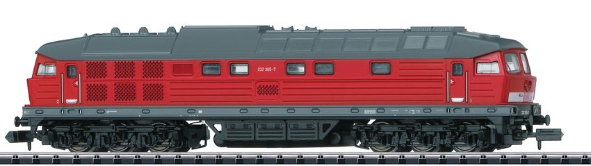
Modell der Diesellokomotive Baureihe 232
D   GB USA   F                                16233
2
Inhaltsverzeichnis:               Seite   Sommaire :                                        Page
Informationen zum Vorbild             4   Informations concernant le modèle réelle              5
Sicherheitshinweise                   6   Remarques importantes sur la sécurité                14
Wichtige Hinweise                     6   Information importante                               14
Funktionen                            6   Fonctionnement                                       14
Hinweise zum Digitalbetrieb           6   Remarques relatives au fonctionement en mode digital 14
Schaltbare Funktionen                 7   Fonctions commutables                                15
Configurations Variablen (CVs)        8   Variables de configuration (CVs)                     16
Wartung und Instandhaltung           18   Entretien et maintien                                18
Ersatzteile                          22   Pièces de rechange                                   22

Table of Contents:                Page
Information about the prototype      5
Safety Notes                        10
Important Notes                     10
Functions                           10
Notes on digital operation          10
Controllable Functions              11
Configuration Variables (CVs)       12
Service and maintenance             18
Spare Parts                         22

                                                                                                    3
Informationen zum Vorbild
Die seit 1973 als Baureihe 132 ausgelieferte Diesellok der
Lokomotivfabrik Woroschilowgrad war eine Weiterent-
wicklung der 1970 in Dienst gestellten BR 130 der DR. Sie
wurde zur Ablösung der Dampflokomotiven beschafft und
im schweren Reise- und Güterzugdienst eingesetzt. In der
Eisenbahnerumgangssprache wurde sie auch als „Ludmilla“
bezeichnet.
Ab 1992 wurden die Maschinen, bei Übernahme der DR
durch die DB, als Baureihe 232 eingereiht.
Spätere Umbauten und der Einsatz verschiedener
leistungsstärkerer Motoren von Kolomna, Caterpillar und
Krupp führten zu den neuen Baureihen 234 und 241. Da die
Ergebnisse der Remotorisierung jedoch nicht den Erwar-
tungen entsprachen, wurden die Umbaumaßnahmen wieder
abgebrochen.
Achsanordnung Co`Co`
Länge ü. Puffer 20.820 mm
Höchstgeschwindigkeit 120 km/h
Dienstmasse 123 t
Nennleistung 2.200 kW (2.940 PS)
Baujahr ab 1970
4Information about the prototype Informations concernant le modèle réel
The class 132 diesel locomotive has been delivered from the La locomotive série 132 construite depuis 1973 par la
Woroschilowgrad locomotive builder since 1973 and was a fabrique de locomotives Woroschilowgrad était un dévelop-
further development of the DR’s class 130 placed into ser- pement de la BR 130 mise en service à la DR en 1970. Elle
vice in 1970. It was purchased to replace steam locomotives a été acquise afin de remplacer les dernières locomotives
and was used in heavy passenger and freight service. The à vapeur au crochet des trains de marchandises et de
railroaders nicknamed it “Ludmilla”. voyageurs lourds. Dans le langage populaire des cheminots,
From 1992 on these units were designated as the class 232 on la surnommait «Ludmilla».
in the takeover of the DR by the DB. A partir de 1992, lors du transfert DR/DB, les machines
Subsequent rebuilding and the use of different more power- furent renumérotées dans la série 232.
ful motors from Kolomna, Caterpillar, and Krupp led to the Des modifications ultérieures et le montage de moteurs
new classes 234 and 241. Since the results of the rebuilding plus puissants provenant des firmes Kolomna, Caterpillar
with new motors did not reach expectations, the rebuilding et Krupp ont été à l‘origine des nouvelles séries 234 et 241.
program was halted. Comme les résultats de cette remotorisation n‘ont pas satis-
fait les attentes, cette expérience n‘a pas eu de suite.
Wheel arrangement C-C Disposition d‘essieux Co`Co`
Length over buffers 20,820 mm / 68 ft. Longueur hors tampons 20 820 mm
3-11/16 in. Vitesse maximale 120 km/h
Maximum speed 120 km/h / 75 mph Poids en ordre de marche 123 t
Service weight 123 metric tons Puissance nominale 2200 kW (2940 CV)
Nominal performance 2,200 kilowatts / (2,940 hp) Construction à partir de 1970
Built starting in 1970
5Sicherheitshinweise Funktionen • Die Lok darf nur mit einem dafür bestimmten Betriebssys- • Eingebaute Elektronik zum wahlweisen Betrieb mit tem eingesetzt werden. konventionellem Gleichstrom-Fahrgerät (max. ±12 Volt), • Die Lok darf nicht mit mehr als einer Leistungsquelle Trix Systems, Trix Selectrix (SX1) und Selectrix 2 (SX2) versorgt werden. oder Digitalsystemen nach NMRA-Norm. • Beachten Sie unbedingt die Sicherheitshinweise in der • Automatische Systemerkennung zwischen Digital- und Bedienungsanleitung zu Ihrem Betriebssystem. Analog-Betrieb. • Analog 14 Volt=, digital 22 Volt~. • Keine automatische Systemerkennung zwischen den • Für den konventionellen Betrieb der Lok muss das Digital-Systemen. Anschlussgleis entstört werden. Dazu ist das Entstörset • Dreilichtspitzensignal im Analogbetrieb nur Vorwärts, im 14972 zu verwenden. Für Digitalbetrieb ist das Entstörset Digitalbetrieb mit der Fahrtrichtung wechselnd. nicht geeignet. • Mit Kinematik für Kurzkupplung und Kupplungsaufnahme • Setzen Sie das Modell keiner direkten Sonneneinstrah- nach NEM. lung, starken Temperaturschwankungen oder hoher Hinweise zum Digitalbetrieb Luftfeuchtigkeit aus. • Beim ersten Betrieb in einem Digital-System (SX1, SX2 • Das verwendete Gleisanschlusskabel darf maximal oder DCC) muss der Decoder auf dieses Digital-System 2 Meter lang sein. eingestellt werden. Dazu ist der Decoder einmal in • ACHTUNG! Funktionsbedingte scharfe Kanten und Spitzen. diesem Digitalsystem zu programmieren (z.B. Adresse Wichtige Hinweise ändern). • Die Bedienungsanleitung und die Verpackung sind • Der Betrieb mit gegenpoliger Gleichspannung im Brems- Bestandteile des Produktes und müssen deshalb aufbe- abschnitt ist mit der werkseitigen Einstellung nicht mög- wahrt sowie bei Weitergabe des Produktes mitgegeben lich. Ist diese Eigenschaft gewünscht, so muss auf den werden. konventionellen Gleichstrombetrieb verzichtet werden • Für Reparaturen oder Ersatzteile wenden Sie sich bitte an (DCC: CV 29 / Bit 2 = 0). Ihren Trix-Fachhändler. • Gewährleistung und Garantie gemäß der beiliegenden Garantieurkunde. • Entsorgung: www.maerklin.com/en/imprint.html 6
Central- Control
                                            66800

                                                                                  f0 - f3 f4 - f7

Schaltbare Funktionen
                                                   1          2   3    4     5

                                                   6          7   8    9     ON

                                                  STOP

                                                         PR       Sx   1/2   Lz

Spitzensignal fahrtrichtungsabhängig   an                                               F0
Geräusch: Signalhorn tief              —                 —                              F1
Geräusch: Betriebsgeräusch             —                 —                              F2
Geräusch: Signalhorn hoch              —                 —                              F3
ABV, aus                               —                 —                              F4
Geräusch: Bremsenquietschen            —                 —                              F5
Geräusch: Bahnhofsansage               —                 —                              F6
Geräusch: Bahnhofsansage               —                 —                              F7
Geräusch: Kabinenfunk                  —                 —                              F8
Geräusch: Schaffnerpfiff               —                 —                              F9
Geräusch: Multiansage                  —                 —                             F10
Geräusch: Zugdurchsage                 —                 —                             F11
Geräusch: Sanden                       —                 —                             F12
Geräusch: Kompressor                   —                 —                             F13
Geräusch: Druckluft ablassen           —                 —                             F14

                                                                                               7
CV Bedeutung Wert DCC ab Werk
1 Adresse 1 – 127 3
2 Minimalgeschwindigkeit 0 – 15 10
3 Anfahrverzögerung 0 – 255 5
4 Bremsverzögerung 0 – 255 5
5 Maximalgeschwindigkeit 0 – 127 60
17 Erweiterte Adresse (oberer Teil) (CV 29, Bit 5=1) 0 – 255 192
18 Erweiterte Adresse (unterer Teil) (CV 29, Bit 5=1) 0 – 255 0
19 Traktionsadresse (0 = inaktiv, Wert + 128 = inverse Fahrtrichtung) 0 – 127 0
21 ^ F1 – F8
Traktions-Modus; Bit 0 – 7 = 0 – 255 0
22 Traktions-Modus; Bit 0 – 1 =^ FLf – FLr, Bit 2 – 5 =
^ F9 – F12 0 – 63 0
Bit 0: Umpolung Fahrtrichtung
Bit 1: Anzahl Fahrstufen 14 - 28/126
29 Bit 2: DCC Betrieb mit Bremsstrecke 0 – 255 6
DCC-, Selectrix- und Gleichstrombetrieb
Bit 5: Adressumfang 17 Bit / 18 Bit
52 Dimmung Licht 0 – 31 31
902 Lautstärke 0 – 255 255
8par Bedeutung Wert SX2 ab Werk
001 Adresse Einer- u. Zehner-Stelle 0 – 99 1
002 Adresse Hunderter- u. Tausender-Stelle 0 – 99 10
011 Anfahrverzögerung 0 – 255 5
012 Bremsverzögerung 0 – 255 5
013 Maximalgeschwindigkeit 0 – 127 60
014 Mindestgeschwindigkeit 0 – 15 10
018 Geschwindigkeit Rangiergang 0 – 127 60
021 Bremsabschnitte; 1 oder 2 0, 1 0
081 Dimmung Licht normal 0 – 31 31
082 Dimmung Licht alternativ 0 – 31 15
Werkseinstellung für SX1: 01-542, erweitert: 00-274
9Safety Notes Functions
• This locomotive is only to be used with the operating • Built-in electronic circuit for optional operation with
system it is designed for. a conventional DC train controller (max. ±12 volts),
• This locomotive must not be supplied with power from Trix Systems, Trix Selectrix (SX1), and Selectrix 2 (SX2),
more than one power pack. or digital systems adhering to the NMRA standards.
• Pay close attention to the safety notes in the instructions • Automatic system recognition between digital and analog
for your operating system. operation.
• Analog 14 volts DC, digital 22 volts AC. • No automatic system recognition between the digital
• The feeder track must be equipped to prevent inter- systems.
ference with radio and television reception, when the • Triple headlights only at the front in analog operation, in
locomotive is to be run in conventional operation. The digital operation triple headlights that change over with
14972 interference suppression set is to be used for this the direction of travel.
purpose. The interference suppression set is not suitable • NEM close coupler mechanism and coupler pocket.
for digital operation. Notes on digital operation
• Do not expose the model to direct sunlight, extreme
• When operating in a digital system for the first time (SX1,
changes in temperature, or high humidity.
SX2, or DCC), the decoder must be set to this digital sys-
• The wire used for feeder connections to the track may be tem. To do this, the decoder must be programmed once in
a maximum of 2 meters / 78 inches long. this digital system (example: change the address).
• WARNING! Sharp edges and points required for operation. • The setting done at the factory does not permit operation
Important Notes with opposite polarity DC power in the braking block.
• The operating instructions and the packaging are a com- If you want this characteristic, you must do without
ponent part of the product and must therefore be kept as conventional DC power operation (DCC: CV 29 / Bit 2 = 0).
well as transferred along with the product to others.
• Please see your authorized Trix dealer for repairs or
spare parts.
• The warranty card included with this product specifies
the warranty conditions.
• Disposing: www.maerklin.com/en/imprint.html
10Central- Control
66800
f0 - f3 f4 - f7
Controllable Functions 1
6
STOP
PR
2
7
3
8
Sx
4
9
1/2
5
ON
Lz
Headlights on F0
Sound effect: Low pitched horn — — F1
Sound effect: Operating sounds — — F2
Sound effect: High pitched horn — — F3
ABV, off — — F4
Sound effect: Squealing brakes — — F5
Sound effect: Station announcements — — F6
Sound effect: Station announcements — — F7
Sound effect: Cab radio — — F8
Sound effect: Conductor whistle — — F9
Sound effect: Multiple announcements — — F10
Sound effect: Train announcement — — F11
Sound effect: Sanding — — F12
Sound effect: Compressor — — F13
Sound effect: Letting off air — — F14
11Factory
CV Discription DCC Value
Setting
1 Address 1 – 127 3
2 Minimum Speed 0 – 15 10
3 Acceleration delay 0 – 255 5
4 Braking delay 0 – 255 5
5 Maximum speed 0 – 127 60
17 Extendet address (upper part) (CV 29, Bit 5=1) 0 – 255 192
18 Extendet address (lower part) (CV 29, Bit 5=1) 0 – 255 0
19 Consist address (0 = inactive, Value + 128 = inverse direction) 0 – 127 0
21 ^ F1 – F8
Motive Power Mode; Bit 0 – 7 = 0 – 255 0
22 Motive Power Mode; Bit 0 – 1 = ^ FLf – FLr, Bit 2 – 5 =
^ F9 – F12 0 – 63 0
Bit 0: Travel direction polarity reversal
Bit 1: number of speed levels 14 – 28/126
29 Bit 2: DCC Operation with braking Block 0 – 255 6
DCC-, Selectrix and DC power operation
Bit 5: address size 17 Bit / 18 Bit
52 Dimming of lights 0 – 31 31
902 Volume 0 – 255 255
12Factory
par Discription SX2 Value
Setting
001 Address for one and ten placeholder 0 – 99 1
002 Address for hundred and thousand placeholder 0 – 99 10
011 Acceleration delay 0 – 255 5
012 Braking delay 0 – 255 5
013 Maximum speed 0 – 127 60
014 Minimum speed 0 – 15 10
018 Speed for switching range 0 – 127 60
021 Braking section; 1 or 2 0, 1 0
081 Dimming of lights, normal 0 – 31 31
082 Dimming of lights, alternative 0 – 31 15
Factory setting for SX1: 01-542, advanced: 00-274
13Remarques importantes sur la sécurité • Elimination : www.maerklin.com/en/imprint.html
• La locomotive ne peut être utilisée qu‘avec le système Fonctionnement
d‘exploitation indiqué.
• Module électronique intégré pour exploitation au choix avec
• La locomotive ne peut être alimentée en courant que par régulateur de marche conventionnel c.c. (max. ±12 volts),
une seule source de courant. Trix Systems, Trix Selectrix (SX1) et Selectrix 2 (SX2) ou
• Veuillez impérativement respecter les remarques sur systèmes numériques conformes à la norme NMRA.
la sécurité décrites dans le mode d’emploi en ce qui • Reconnaissance automatique du système entre exploita-
concerne le système d’exploitation. tions numérique et analogique.
• Analogique 15 volts=, digital 22 volts ~. • Pas de reconnaissance automatique du système entre
• Pour l’exploitation de la locomotive en mode conventi- les systèmes numériques.
onnel, la voie de raccordement doit être déparasitée. A • En mode d’exploitation analogique, fonction du fanal
cet effet, utiliser le set de déparasitage réf. 14972. Le set à trois feux uniquement en marche avant ; en mode
de déparasitage ne convient pas pour l’exploitation en d’exploitation numérique, inversion en fonction du sens
mode numérique. de marche.
• Ne pas exposer le modèle à un ensoleillement direct, • Avec boîtier normalisé NEM à élongation pour attelage
à de fortes variations de température ou à un taux court.
d‘humidité important.
• Le câble de raccordement à la voie utilisé ne doit en Remarques relatives au fonctionnement en mode digital
aucun cas dépasser deux mètres. • Une première exploitation en système numérique
• ATTENTION! Pointes et bords coupants lors du fonction- (SX1, SX2 ou DCC) exige un réglage correspondant du
nement du produit. décodeur. A cet effet, le décodeur doit être programmé
une fois dans ce système numérique (modification de
Information importante l’adresse par ex.).
• La notice d‘utilisation et l’emballage font partie intégrante • L’exploitation avec courant continu de polarité inverse dans
du produit ; ils doivent donc être conservés et, le cas les sections de freinage n’est pas possible avec le réglage
échéant, transmis avec le produit. d’usine. Si cette propriété est désirée, il faut alors renoncer
• Pour toute réparation ou remplacement de pièces, à l’exploitation conventionnelle en courant continu
adressez vous à votre détaillant-spécialiste Trix. (DCC: CV 29 / Bit 2 = 0).
• Garantie légale et garantie contractuelle conformément
au certificat de garantie ci-joint.
14Central- Control
66800
f0 - f3 f4 - f7
Fonctions commutables 1
6
STOP
PR
2
7
3
8
Sx
4
9
1/2
5
ON
Lz
Fanal éclairage activé F0
Bruitage : trompe, signal grave — — F1
Bruitage : Bruit d’exploitation — — F2
Bruitage : trompe, signal aigu — — F3
ABV, désactivé — — F4
Bruitage : Grincement de freins — — F5
Bruitage : Annonce en gare — — F6
Bruitage : Annonce en gare — — F7
Bruitage : Radio cabine — — F8
Bruitage : Sifflet Contrôleur — — F9
Bruitage : Annonce multiple — — F10
Bruitage : Annonce en train — — F11
Bruitage : Sablage — — F12
Bruitage : Compresseur — — F13
Bruitage : Échappement de l‘air comprimé — — F14
15CV Signification Valeur DCC Valeur Parm. Usine
1 Adresse 1 – 127 3
2 Vitesse min 0 – 15 10
3 Temporisation d‘accélération 0 – 255 5
4 Temporisation de freinage 0 – 255 5
5 Vitesse maximale 0 – 127 60
17 Adresse étendue (partie supérieure) (CV 29, Bit 5=1) 0 – 255 192
18 Adresse étendue (partie inférieure) (CV 29, Bit 5=1) 0 – 255 0
19 Adresse pour la traction (0 = inactif, Valeur + 128 = direction inverse) 0 – 127 0
21 ^ F1 à F8
Mode traction, bit 0 à 7 = 0 – 255 0
22 Mode traction; bit 0 à 1 =^ FLf à FLr, Bit 2 à 5 =
^ F9 à F12 0 – 63 0
Bit 0: inversion de polarité, sens de marche
Bit 1: Nombre de crans de marche 14 – 28/126
29 Bit 2: Exploitation DCC avec zone de freinage. 0 – 255 6
DCC-, Selectrix et courant continu
Bit 5: taille d‘adresse 7 Bits / 14 Bits
52 Variation lumière 0 – 31 31
902 Volume 0 – 255 255
16par Signification Valeur SX2 Valeur Parm. Usine
001 Adresse unités et décimales 0 – 99 1
002 Adresse centaines et milliers 0 – 99 10
011 Temporisation d’accélération 0 – 255 5
012 Temporisation de freinage 0 – 255 5
013 Vitesse maximale 0 – 127 60
014 Vitesse minimale 0 – 15 10
018 Vitesse de manoeuvre 0 – 127 60
021 Sections de freinage, 1 ou 2 0, 1 0
081 Variation lumière normale 0 – 31 31
082 Variation lumière alternative 0 – 31 15
Paramètres d’usine pour SX1: 01-542, étendus : 00-274
17OIL
40h
7149
Märklin 66626
7149
X
RI
IT
IN
66623 M
18a
a
b b
19! ! 20
a

                        b
    a                       E15 0250 00

                        d

b                   c

                c
        d
                                     21
22
13
2
1 3
1
2 4
6
4 6
6 5
10
8
9
10
11 8 12
7
11
2
12
12
Details der Darstellung
12 2 können von dem Modell
abweichen.1 Puffer E191 022 Hinweis: Einige Teile werden nur ohne oder mit anderer
2 Schraube E19 7035 28 Farbgebung angeboten.
3 Schnittstellenstecker / Decoder — Teile, die hier nicht aufgeführt sind, können nur im Rahmen
4 Glühbirne E232 115 einer Reparatur im Märklin-Reparatur-Service repariert
5 Motorhalteklammern E13 1481 00 werden.
6 Motor E234 031
7 Drehgestell E308 805
8 Kontaktscheibe E13 1959 15
9 Drehgestell E308 806
10 Zwischenrad E12 2021 00
11 Haftreifen E12 2258 00
12 Kupplung E234 168
13 Lautsprecher E101 066
Glühlampe E15 0250 00
23Due to different legal requirements regarding electro-magnetic compatibility,
this item may be used in the USA only after separate certification for FCC com-
pliance and an adjustment if necessary.
Use in the USA without this certification is not permitted and absolves us of any
liability. If you should want such certification to be done, please contact us –
also due to the additional costs incurred for this.
Gebr. Märklin & Cie. GmbH
Stuttgarter Straße 55 - 57
73033 Göppingen 268975/1216/Sm2Ef
Germany Änderungen vorbehalten
www.trix.de www.maerklin.com/en/imprint.html © Gebr. Märklin & Cie. GmbHSie können auch lesen