Montageanleitung - Lekolar
←
→
Transkription von Seiteninhalten
Wenn Ihr Browser die Seite nicht korrekt rendert, bitte, lesen Sie den Inhalt der Seite unten
Montageanleitung
Assembly Instructions       Montagehandleiding                      Instructions de                    Instrucciones de
                                                                       montage                              montaje

                                                   510018

                                         Spielparcours
                                                      RM-code:

                                                                                                      V-01-met (2021/06/15)

               eibe Produktion + Vertrieb GmbH & Co. KG | Industriestraße 1 | 97285 Röttingen | www.eibe.de           V-2021-04-14
Achtung:
Unterlagen unbedingt aufbewahren! Bei allen Fragen und Reklamationen bitte RM-code angeben.
Montagehinweis:
Die Montageanleitung ist wie folgt in dieser Reihenfolge gegliedert:
Textliche Hinweise & Symbol-Erklärung pro Sprache / Geräte-Daten symbolisch Dargestellt -> Seite 12 /
Wartungsintervalle pro Baugruppe (wenn erforderlich) / Zeichnungen (Mindestraum, Fundamentpläne,
Aufprallflächenplan) / Lieferumfang / Aufbauschritte / 180°-Ansicht / Detailblätter
Nehmen sie sich vor der Montage Ihres Artikels Zeit, die betroffenen Anmerkungen gründlich zu lesen. Beachten Sie
konsequent alle Symbole. Die Aufbauhinweise in der Wartungsanleitung sind zu beachten. Weitere Informationen
finden Sie ebenfalls in der beiliegenden Wartungsanleitung! Weiter sind ggf. in den nachfolgenden Seiten dieser
Dokumentation Sachverhalte z.B. bei Aufbauanleitungsschritten und Detailblättern angegeben, die ebenfalls bei der
jährlichen Hauptinspektion zu berücksichtigen sind. Für eine erfolgreiche und schnelle Montage arbeiten Sie Schritt für
Schritt die vorgegebenen Aufbauschritte ab. Im jeweiligen Aufbauschritt sehen Sie die benötigten Einzelteile, die
Anbauposition und den Verweis zu den passenden Detailblättern. Ein Detailblatt kann mehrfach zum Einsatz kommen.
Unsere gelieferten Teile sind alle mit Teilenummern versehen. Achten Sie bei der Montage auf die korrekte Verwendung
der Teile durch die angegebenen Teilenummern im Aufbauschritt bzw. dem Detailblatt.
Anforderungen an das Geländeprofil:
Bitte orientieren Sie sich an den Angaben in unseren Ausschreibungsunterlagen und dem Fundamentplan. Bitte
vergewissern Sie sich vor Inbetriebnahme, dass alle Montagehilfsmittel entfernt sind. Wenn am Aufstellungsort
außergewöhnliche Bedingungen festzustellen sind wie z.B. Torfboden oder gefrorener Boden, dann müssen diese
Bedingungen bei der Fundamentdimensionierung beachtet werden.
Fußnoten:
Aufprallfläche
a) Die gelbe (innere) Fläche zeigt die Aufprallfläche mit Anforderungen an die Stoßdämpfung.
Bodenbeschaffenheit innerhalb der Aufprallfläche (DE/AT/NL):
Synthetischer
Sand Kies Holzschnitzel Rasen Oberboden Beton Stein
Fallschutz
Bodenbeschaffenheit innerhalb der Aufprallfläche (sonstige Länder):
Synthetischer
Sand Kies Holzschnitzel Rasen Oberboden Beton Stein
Fallschutz
b) Die äußere Linie umschließt die gesamte Aufprallfläche.
Generell muss um jedes Spielgerät ein Abstand von 1,5m bemessen werden, der frei von harten und
scharfkantigen sowie vorstehenden Teilen ist.
Legende Fundamentliste
ID = Fundamentnummer
Type = OF=Ortbetonfundament C20/25,
= FFk=eibe-Fertigfundament,
= FFr=eibe-Fertigfundament rund,
= FFg=eibe-Fertigfundament groß,
= FL3=NACH Montage erstellen!
X = horizontales Maß zum 0-Punkt
Y = vertikales Maß zum 0-Punkt
Z = Lochtiefe zum Oberboden
α = Drehung Fundament
FS = Größe Fundament: Länge x Breite x Höhe (L x W x H)
DS = Größe Drainageschicht: Länge x Breite x Höhe (L x W x H)
SP = Rutschenanbaupunkt (Slide Point)
Rutschen sind nicht im Lieferumfang enthalten.
Sichere Benutzung nur mit eibe Rutsche oder Schließen der Öffnung entsprechend EN 1176.
Detaillierte Angaben wie z.B. Aufprallfläche oder Fundamente entnehmen Sie bitte der separat
beiliegenden Rutschen-Montageanleitung.
eibe Produktion + Vertrieb GmbH & Co. KG | Industriestraße 1 | 97285 Röttingen | www.eibe.de 2/36
Gerätedaten                                     Norm                                            Anzahl Benutzer

Altersklasse                                    Mindestraum                                     Maximale freie Fallhöhe

Wartungsintervall in Monate                     Wartung                                         Übersichtsplan

Pfostenübersicht                                Fundamentplan                                   eibe-Fertigfundament

Ortbetonfundament                               Fundamentliste                                  Detailblatt / Aufbaubeispiel

                                                Ortbetonfundament mit Betonsorte
Aufprallflächenplan                                                                             Lieferumfang
                                                C20/25

                                                Verschleißteil (Nicht in der
Nicht im Lieferumfang enthalten                                                                 Wartezeit in Tagen
                                                Gewährleistung mit inbegriffen)

Aufbauschritt                                   Ansicht um 90° gedreht                          Ansicht um 180° gedreht

Beipack                                         Anzeichnen                                      Maße angeben in m

Maße angegeben in cm                            Messen                                          Ausrichten

                                                Bohren (t = Bohrungstiefe, ø =
Bohren (ø = Bohrdurchmesser)                                                                    Mit Hammer befestigen
                                                Bohrdurchmesser)

                                                Senkbohrungen mit
Schrauben festziehen                                                                            Abschneiden
                                                Verschlussstopfen verschließen

Abstand                                         Achtung                                         Nach Montage entsorgen

Kein Durchhang                                  Keine Überschneidung                            Schraubensicherung

Korrekt                                         Falsch                                          Konzipiert für den betreuten Bereich

                                                Darf nur unter Aufsicht benutzt
Konzipiert für den Innenbereich                                                                 Checkliste
                                                werden!

größtes Teil                                    schwerstes Teil                                 Anzahl Fundamente

                                                Aufprallfläche mit stoßdämpfenden
Fundamentlevel                                                                                  Aufprallfläche gesamt
                                                Anforderungen

Drainage                                        Aushub

                eibe Produktion + Vertrieb GmbH & Co. KG | Industriestraße 1 | 97285 Röttingen | www.eibe.de                   3/36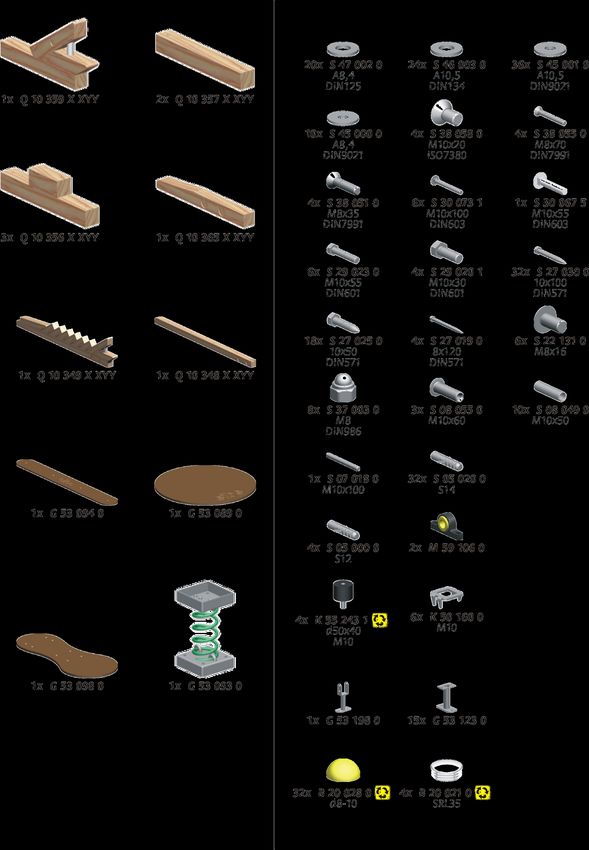
Attention:
Please keep these documents! Please indicate the RM-code on all inquiries and complaints.
Installation notes:
The assembly instructions are structured as follows in this order:
Textual notes & symbol explanation per language / Unit data shown symbolically -> page 12 / Maintenance intervals per
assembly group (if required) / Drawings (minimum space, foundation plans, impact area plan) / Scope of delivery /
Assembly steps / 180° view / Detail sheets /
Before assembling your article, take the time to read the relevant notes thoroughly. Consistently observe all symbols.
Observe the assembly instructions in the maintenance instructions. Further information can also be found in the
enclosed maintenance instructions! In addition, the following pages of this documentation may contain information,
e.g. on assembly instructions and detailed sheets, which must also be observed during assembly. Detail sheets, which
must also be taken into account during the annual main inspection. For a successful and quick assembly, work through
the specified assembly steps step by step. In each assembly step you will see the required individual parts, the assembly
position and the reference to the appropriate detail sheets. A detail sheet can be used several times. Our supplied parts
are all marked with part numbers. When assembling, make sure that you use the parts correctly by referring to the part
numbers given in the assembly step or the detail sheet.
Site requirements:
Please refer to the information in our tender documents and in the foundation plan. Before putting the equipment into
service, ensure that all assembly tools have been removed. Unusual site conditions such as peat soil or frozen
underground must be taken into account for the dimensioning of the foundation.
Fußnoten:
Impact surface
a) Yellow (inner) area shows the impact surface with shock absorption requirements.
Surfacing inside the impact area (DE/AT/NL):
Impact-
Sand Gravel Wood chips turf Top soil concrete stone
attenuating tiles
Surfacing inside the impact area (other countries):
Impact-
Sand Gravel Wood chips turf Top soil concrete stone
attenuating tiles
b) The outer line encloses the entire impact surface.
Generally, a space of 1.5 m around each piece of playground equipment must be kept free of hard and sharp-
edged as well as protruding parts.
Key foundation list
ID = foundation number
Type = OF=concrete foundation C20/25,
= FFk=eibe-prefab foundation small,
= FFr=eibe-prefab foundation round,
= FFg=eibe-prefab foundation large,
= FL3=Prepare AFTER the installation!
X = horizontal measure to 0-point
Y = vertical measure to 0-point
Z = op edge of foundation to surface soil
α = orientation of foundation
FS = Size foundation: length x width x height (L x W x H)
DS = Size drainage layer: length x width x height (L x W x H)
SP = Slide attachment point (Slide Point)
Slides are not included.
Safe use of the equipment only with original eibe slide or by closing the slide opening in accordance with DIN EN
1176.
For detailed information, e.g. impact area or foundations, please see the enclosed slide installation instruction.
eibe Produktion + Vertrieb GmbH & Co. KG | Industriestraße 1 | 97285 Röttingen | www.eibe.de 4/36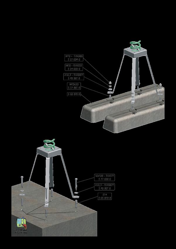
Equipment data                                    Safety standard                                 Number of users

Age group                                         Minimum space                                   Maximum height of fall

Maintenance interval in months                    Maintenance                                     Site plan

Posts overview                                    Foundation plan                                 eibe prefab foundation

Concrete foundation                               Foundation list                                 Detail sheet / assembly example

                                                  Concrete foundation with concrete
Impact zone plan                                                                                  Scope of supply
                                                  C20/25

                                                  Wearing part (excluded from
Not included in the delivery                                                                      Waiting period in days
                                                  guarantee)

Assembly step                                     View rotated by 90°                             View rotated by 180°

Accessories kit                                   Marking                                         Dimensions in m

Dimensions in cm                                  Measuring                                       Alignment

                                                  Drilling (t = drilling depth, ø = drilling
Drilling (ø = drilling diameter)                                                                  Fix with hammer
                                                  diameter)

                                                  Close counterbores with closure
Tightening screws                                                                                 Cutting off
                                                  plugs

Space                                             Attention                                       Dispose after assembly

No passage                                        No overlap                                      Screw locking

Correct                                           Wrong                                           Designed for supervised play areas

                                                  May only be used under
Designed for indoor play areas                                                                    Checklist
                                                  supervision!

Largest part                                      Heaviest part                                   Number of foundations

                                                  Impact zone with shock absorbing
Foundation level                                                                                  Impact zone total
                                                  requirements

Drainage                                          Excavation

                  eibe Produktion + Vertrieb GmbH & Co. KG | Industriestraße 1 | 97285 Röttingen | www.eibe.de               5/36
Attentie
"Deze documenten dient u te bewaren! Bij alle vragen of reclamaties graag de RM-code aangeven. "
Montage instructie
De montage-instructies zijn als volgt opgebouwd:
Tekstuele informatie & uitleg van symbolen per taal / Toestelgegevens symbolisch weergegeven ->
pagina 12 / Onderhoudsintervallen per montage (indien nodig) / Tekeningen (minimale ruimte ,
funderingsplannen, plan van impactgebied) / leveringsomvang / Bouwstappen / 180 ° zicht / Detailbladen
Neem de tijd om de relevante opmerkingen aandachtig te lezen voordat u uw aangekochte artikel gaat
monteren. Neem alle symbolen strikt in acht. De montage-instructies in de onderhoudshandleiding
moeten in acht worden genomen. Verdere informatie vindt u ook in de bijgevoegde
onderhoudsinstructies! Bovendien kunnen de volgende pagina's van deze documentatie informatie
bevatten zoals montage-instructies en worden er specificatiebladen verstrekt waarmee ook bij de
jaarlijkse hoofdinspectie rekening moet worden gehouden. Voor een succesvolle en snelle installatie
doorloopt u de aangegeven montagestappen stap voor stap. In de betreffende montagestap ziet u de
benodigde afzonderlijke onderdelen, de montagepositie en de verwijzing naar de betreffende
detailbladen. Een detailblad kan meerdere keren worden gebruikt. Onze geleverde onderdelen zijn
allemaal voorzien van onderdeelnummers. Zorg er tijdens de montage vo or dat de onderdelen correct
worden gebruikt met de onderdeelnummers die zijn gespecificeerd in de montagestap of op het
detailblad.
Locatie vereisten
Graag wijzen wij u op de documentatie van onze offertes en fundamentplannen. Voordat u het
speeltoestel in gebruik stelt controleren of alle gereedschappen en bouwmaterialen zijn weggehaald.
Afwijkende terrein condities zoals vochtige grond, vorst hebben invloed op de dimensionering van de
fundering.
Voetnoten:
Valdempende ondergrond
a) Gele ( binnen) ruimte geeft de ruimte aan met valdempingseisen.
Grondomstandigheden binnen de vrije valruimte (DE/AT/NL):
Rubber /
natuurlijke
zand grind houtsnippers syntetische gras beton stehen
bodemlaag
valonderground
Grondomstandigheden binnen de vrije valruimte (andere landen):
Rubber /
natuurlijke
zand grind houtsnippers syntetische gras beton stehen
bodemlaag
valonderground
b) De buitenste lijn geeft de volledige obstakelvrije ruimte aan .
In het algemeen moet rond elk speeltoestel een afstand van 1,5 m worden gemeten, vrij van harde, scherpe en
uitstekende delen.
Legenda funderingslijst
ID = funderingsnummer
Type = OF=Stortbeton C20/25,
= FFk=eibe-prefabfundering klein,
= FFr=eibe-prefabfundering rond,
= FFg=eibe-prefabfundering groot,
= FL3=NA montage aan te brengen!
X = horizontale maten naar 0-punt
Y = verticale maten naar 0-punt
Z = bovenzijde van de fundering tot grondniveau
α = orientatie van de fundering
FS = Grootte fundering: lengte x breedte x hoogte (L x B x H)
DS = Grootte drainagelaag: lengte x breedte x hoogte (L x B x H)
SP = Schuif bevestigingspunt (Slide Point)
Glijbanen zijn niet leveringsomvang opgenomen.
Veilig gebruik van het speeltoestel door toepassing van de orginele eibe glijbaan en installatie met in achtneming
van het juist sluiten van kieren van de glijbaan instap volgens DIN EN 1176.
Gedetailleerde opgave van bijvoorbeeld opvangzone, fundamentlocatie is in de apart bijgevoegde
montagehandleiding van de glijbaan opgenomen.
eibe Produktion + Vertrieb GmbH & Co. KG | Industriestraße 1 | 97285 Röttingen | www.eibe.de 6/36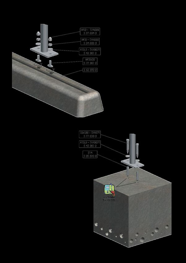
Toestelgegevens                                  Norm                                            Aantal gebruikers

Leeftijds doelgroep                              Minimum ruimte                                  Maximale valhoogte

Onderhoudsfrequentie in maanden                  Onderhoud                                       Overzichtsplan

Palenoverzicht                                   Funderingsplan                                  eibe prefabfundering

                                                                                                 Detail uitwerking /
Stortbeton                                       Fundamentenlijst
                                                                                                 montagevoorbeeld

Obstakelvrije ruimte                             Stortbeton volgens C20/25                       Leverinsgomvang

                                                 Slijtage onderdeel (uitgesloten van
Niet in leveringsomvang opgenomen                                                                Wachttijd in dagen
                                                 garantie)

Montagestap                                      Beeld gedraaid met 180°                         Beeld gedraaid met 180°

Bijpak                                           Markering                                       Maten aangeduid in m

Maten aangeduid in cm                            Meten                                           Meten

                                                 Boren (D = diepte boring, ø =                   Boren (D = diepte boring, ø =
Boren (ø = boring diameter)
                                                 diameter boring)                                diameter boring)

                                                 Afdoppen met bijgeleverde
Schroeven vastdraaien                                                                            Afsnijden
                                                 afdekdoppen

Afstand                                          Let op                                          Na montage verwerken

Geen doorgang                                    Geen overlap                                    Schroefbevestiging

                                                                                                 Ontworpen voor speelplaatsen met
Correct                                          Fout
                                                                                                 toezicht

Ontworpen voor indoor                            Mag alleen onder toezicht worden
                                                                                                 checklist
speelomgevingen                                  gebruikt!

Grootste component                               Zwaarste component                              Aantal fundamenten

                                                 Opvangzone met
Fundering                                                                                        Opvangzone totaal
                                                 schokabsorberende eisen

Afvoer                                           Uitgraving

                 eibe Produktion + Vertrieb GmbH & Co. KG | Industriestraße 1 | 97285 Röttingen | www.eibe.de                7/36
Attention:
Conservez incondicionellement les documents! Communiquez pour toutes les demandes et les réclamations le RM-code, s'il
vous plaît.
Indications du montage:
Les instructions de montage sont organisées de la manière suivante dans cet ordre:
Indications textuels & explication des symboles par langue / Les données de l‘équipement représentées
symboliquement -> Page 12 / Intervalles de maintenance par ensemble (si nécessaire) / Dessin (Espace
minimale, plans des fondations, plan des surfaces d‘impact) / Ce que la livraison comprend / Aufbauschritte
/ Vue à 180° / Fiches techniques
Prenez le temps avant le montage de votre article afin de lire attentivement les notes concernées. Faites
attention à toutes les symbols de manière rigureuse. Les indications d’installation dans les instruction
de maintenance doivent être prises en compte. Vous trouvere z des renseignements supplémentaires
également dans les instructions de maintenance jointes! Ensuite, le cas échéant, des circomstances
sont indiquées dans les pages suivantes de cette documentation, par exemple, dans les phases des
instructions d’installation et des fiches techniques, qui doivent être prises em compte aussi dans
l’inspection principale annuelle. Pour un montage avec succès et rapide liquidez étape par étape les
phases d’installation prédeterminées. Dans la phase d’installation respective v ous verrez les composants
nécessaires, la position d’intégration et la référence aux fiches techniques adéquates. Une fiche technique
peut être utilisée à plusieurs reprises. Toutes nos pièces fournies sont pourvues de numéros de pièce.
Veillez à une utilisation correcte des pièces dans le montage à travers des numéros de pièces indiqués
dans la phase d’installation ou dans la fiche technique.
Exigences quant au profil du terrain:
S’il vous plaît, orientez vous aux informations dans nos dossiers d’appel d’o ffres et le plan des fondations.
S’il vous plaît, assurez-vous avant la mise en service que tous les outils de montage soient éloignés. Lors
de la constatation des conditions extraordinaires, telles que les sols tourbeux ou gelés, dans le lieu du
montage, celles-ci doivent donc être prises en compte pour le dimensionnement des fondations.
Notes infrapaginales:
Surface d’impact
a) La surface (interne) jaune montre la surface d’impact avec les exigences quant à l’absorption de chocs.
Nature du sol dans les limites de la surface d’impact: (DE/AT/NL):
couche
dalles de
sable gravier roulés copeaux de bois gazon superficielle du béton pierre
sécurité
sol
Nature du sol dans les limites de la surface d’impact: (d'autres pays):
couche
dalles de
sable gravier roulés copeaux de bois gazon superficielle du béton pierre
sécurité
sol
b) La ligne extérieure comprend toute la surface d‘impact.
En général, une distance de 1,5 m doit être mesurée autour de chaque équipement de jeu, qui doit être exempt de parties dures
et tranchantes ainsi que de parties saillantes.
Légende liste de fondations
ID = Numéro de fondation
Type = OF=Fondation en béton à couler sur place C20/25,
= FFk=fondation préfabriquée eibe petite,
= FFr=fondation préfabriquée eibe ronde,
= FFg=fondation préfabriquée eibe grande,
= FL3=Créer APRÈS le montage!
X = Mesure horizontale au point 0
Y = Bord supérieur fondation pour le sol supérieur
Z = Bord supérieur fondation pour le sol supérieur
α = Rotation des fondations
FS = Taille de la fondation: longueur x largeur x hauteur (L xlx H)
DS = Taille de la couche de drainage: longueur x largeur x hauteur (L xlx H)
SP = Faites glisser le point d'attache (Slide Point)
Les toboggans ne sont pas inclus dans ce que la livraison comprend.
L’utilisation n’est que secure avec un toboggan eibe ou avec la fermeture de l’ouverture selon l’EN 1176..
Pour des informations détaillées telles que la surface d'impact ou les fondations, veuillez-vous référer aux instructions
d'installation du toboggan jointes séparément.
eibe Produktion + Vertrieb GmbH & Co. KG | Industriestraße 1 | 97285 Röttingen | www.eibe.de 8/36
Données de la structure                          Norme                                           Quantité d‘utilisateurs

Classe d‘âge                                     Espace minimal                                  Hauteur de chute livre maximale

Interval de maintenance en mois                  Maintenance                                     Plan d‘ensemble

Vue d’ensemble des poteaux                       Plan des fondations                             Fondation préfabriquée eibe

Fondation en béton à couler sur                                                                  Feuille de détail / Exemple de
                                                 Liste des fondations
place                                                                                            construction

                                                 Fondation en béton à couler sur
Plan de surface d‘impact                                                                         Ce que la livraison comprend
                                                 place avec sorte de béton C20/25

Non inclus dans ce que la livraison              Pièce consommable (non inclue
                                                                                                 Temps d’attente en jours
comprend                                         dans la garantie)

Phase de construction                            Vue tournée 90°                                 Vue tournée 180°

Accéssoires                                      Traçage                                         Indiquer les dimensions en m

Dimensions indiquées en cm.                      Mésurer                                         Aligner

                                                 Percer (t = Profondeur de perçage,
Percer (ø = Diamètre de perçage)                                                                 Fixer avec un marteau
                                                 ø = Diamètre de perçage)

                                                 Fermer les trous fraisés avec des
Serrer les vis                                                                                   Couper
                                                 bouchons de fermeteure

Distance                                         Attention                                       Éliminer après le montage

Aucune courbure                                  Acun chevauchement                              Dispositif de sécurité pour vis

Correct                                          False                                           Conçu pour les aires surveillées

Conçu pour les aires dans l‘intérieur            Ne peut être utilisé que sous
                                                                                                 Aide-mémoire
des édifices                                     surveillance!

Elément le plus grand                            Elément le plus lourd                           Nombre des fondations

                                                 Surface d'impact avec des
Niveau de fondation                                                                              Surface d'impact le total
                                                 exigences d'absorption des chocs

Drainage                                         Excavation

                 eibe Produktion + Vertrieb GmbH & Co. KG | Industriestraße 1 | 97285 Röttingen | www.eibe.de                  9/36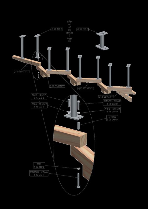
Atención:
¡Guarde siempre los documentos! Indique en todas preguntas y reclamaciones el RM -code (vea la página del título de la
instrucción del montaje).
Indicaciones del montaje:
Las instrucciones de montaje están estructuradas en este orden:
Indicaciones textuales & explicación de símbolos por cada idioma / Datos del equipo representados
simbólicamente -> Página 12 / Intervalo de mantenimiento por cada conjunto (cuando sea necesario) /
Dibujos (Espacio mínimo, planos de la cimentación, plano de las superficies de impacto) / Alcance de
suministro / Pasos de la instalación / Vista de 180° / Hojas de detalle
Tómese el tiempo antes del montaje de su artículo para leer en profundidad las notas correspondientes.
Preste atención a todos los símbolos rigurosamente. Las indicaciones de instalación en las instrucciones
de mantenimiento deben ser tenidas en cuenta. ¡Encontrará informaciones ad icionales del mismo
modo en las instrucciones adjuntas de mantenimiento! Adicionalmente, cuando proceda, circunstancias
son indicadas en las páginas siguientes de esta documentación, tales como pasos de las instrucciones de
montaje y hojas de detalle, que igualmente deben ser consideradas durante la inspección principa l annual.
Para un montaje rápido y exitoso procese paso a paso los pasos de instalación predeterminados. En la
correspondiente fase de instalación ve los repuestos necesarios, la posición de i ntegración y la remisión a las
hojas adecuadas de detalle. Una hoja de detalle puede ser empleada en varias ocasiones. Todas partes
suministradas están provistas de números de parte. Preste atención durante el montaje a la aplicación
correcta de las partes a través de los números indicados de parte en la fase de instalación o en la hoja de
detalle.
Requisitos para el perfil del terreno:
Por favor, oriéntese a las informaciones en nuestra documentación de licitación y el plan de las
cimentaciones. Por favor, asegúrese antes de la puesta en servicio de que todas las herramientas de montaje
estén alejadas. Cuando se comprueben condiciones extraordinarias, tales como suelo de turba o suelo
congelado, en el lugar de instalación, entonces deben considerarse estas condiciones en el
dimensionamiento de las cimentaciones.
Notas a pie de página:
Superficie de impacto
a) la superficie amarilla (interna) muestra la superficie de impacto con requisitos de absorción de choques.
Naturaleza del suelo dentro de la superficie de caída: (DE/AT/NL):
protección
arena grava viruta de madera sintética contra césped tierra hormigón piedra
caídas
Naturaleza del suelo dentro de la superficie de caída: (otros paises):
protección
arena grava viruta de madera sintética contra césped tierra hormigón piedra
caídas
b) La línea exterior rodea toda la superficie de choque.
Generalmente se debe medir una distancia de 1,5 m. alrededor de cada equipo de juego, la cual está libre de partes con aristas
duras y agudas, así como de partes salientes.
Leyenda de la lista de cimentaciones
ID = número de cimentación
Type = OF=cimetación de cemento in situ C20/25,
= FFk=cimentación prefabricada eibe pequeña,
= FFr=cimentación prefabricada eibe redonda,
= FFg=cimentación prefabricada eibe grande,
= FL3=realizar TRAS el ontaje!
X = medida horizontal hacia el punto 0
Y = medida vertical hacia el punto 0
Z = Borde superior de la cimentación hacia el suelo superior
α = Giro de la cimentación
FS = Tamaño de la cimetación: longitud x anchura x altura (L x W x H)
DS = Tamaño de la capa de drenaje: longitud x anchura x altura (L x W x H)
SP = Deslice el punto de fijación (Slide Point)
Los toboganes no están incluidos en el alcance del suministro.
El uso seguro solamente es posible con el tobogán de eibe o bien cerrando la apertura de acuerdo con la DIN EN 1176. Información
detallada como superficie de impacto o cimentaciones, consulte las instrucciones de montaje de toboganes incluidas por separado.
eibe Produktion + Vertrieb GmbH & Co. KG | Industriestraße 1 | 97285 Röttingen | www.eibe.de 10/36Datos del equipo Norma Número de usuarios
Clasificación de edad Espacio mínimo Altura de caída libre máxima
Invervalo de mantenimiento en
Mantenimiento Plan general
meses
Visión general de los postes Plan de cimentación Cimentación prefabricada eibe
Hoja de detalle / Ejemplo de
Cimentación de hormigón in situ Lista de cimentación
montaje
Cimentaciäon de hormigón in situ
Plano de la zona de impacto Alcance del suministro
con tipo de hormigón C20/25
No incluido en el alcance del Pieza de desgate (no incluida en la
Tiempo de espera en días
suministro garantía)
Fase de construción Vista rotada 90° Vista rotada 180°
Accesorios Indicios Medida indicada en m
Talla indicada en cm. Medir Alineación
Taladrar (t = profundidad del
Taladrar (ø = diámetro del taladro) Fijar con un martillo
taladro, ø = diámetro del taladro)
Taladro avellanado con tapones de
Apretar los tornillos Cortar
cierre
Distancia Atención Eliminar tras el montaje
Ningún combadura Ningún solapamiento Seguro de tornillos
Correcto Falso Diseñado para las áreas vigiladas
¡Sólo puede ser usado bajo
Diseñado para las áreas interiores lista de comprobación
supervisión!
Pieza más grande Pieza más pesada Número de fundamentos
Superficie de impacto con requisitos
Nivel fundamento Superficie de impacto total
de absorción de impactos
Drenaje Excavación
eibe Produktion + Vertrieb GmbH & Co. KG | Industriestraße 1 | 97285 Röttingen | www.eibe.de 11/36EN1176 - 1 / 7 8,22 x 7,87 x 2,33 m
0,53 m
0+ 6
eibe Produktion + Vertrieb GmbH & Co. KG | Industriestraße 1 | 97285 Röttingen | www.eibe.de 12/36eibe Produktion + Vertrieb GmbH & Co. KG | Industriestraße 1 | 97285 Röttingen | www.eibe.de 13/36
eibe Produktion + Vertrieb GmbH & Co. KG | Industriestraße 1 | 97285 Röttingen | www.eibe.de 14/36
eibe Produktion + Vertrieb GmbH & Co. KG | Industriestraße 1 | 97285 Röttingen | www.eibe.de 15/36
eibe Produktion + Vertrieb GmbH & Co. KG | Industriestraße 1 | 97285 Röttingen | www.eibe.de 16/36
eibe Produktion + Vertrieb GmbH & Co. KG | Industriestraße 1 | 97285 Röttingen | www.eibe.de 17/36
eibe Produktion + Vertrieb GmbH & Co. KG | Industriestraße 1 | 97285 Röttingen | www.eibe.de 18/36
eibe Produktion + Vertrieb GmbH & Co. KG | Industriestraße 1 | 97285 Röttingen | www.eibe.de 19/36
eibe Produktion + Vertrieb GmbH & Co. KG | Industriestraße 1 | 97285 Röttingen | www.eibe.de 20/36
AS 1

eibe Produktion + Vertrieb GmbH & Co. KG | Industriestraße 1 | 97285 Röttingen | www.eibe.de   21/36
eibe Produktion + Vertrieb GmbH & Co. KG | Industriestraße 1 | 97285 Röttingen | www.eibe.de 22/36
eibe Produktion + Vertrieb GmbH & Co. KG | Industriestraße 1 | 97285 Röttingen | www.eibe.de 23/36
eibe Produktion + Vertrieb GmbH & Co. KG | Industriestraße 1 | 97285 Röttingen | www.eibe.de 24/36
eibe Produktion + Vertrieb GmbH & Co. KG | Industriestraße 1 | 97285 Röttingen | www.eibe.de 25/36
eibe Produktion + Vertrieb GmbH & Co. KG | Industriestraße 1 | 97285 Röttingen | www.eibe.de 26/36
eibe Produktion + Vertrieb GmbH & Co. KG | Industriestraße 1 | 97285 Röttingen | www.eibe.de 27/36
eibe Produktion + Vertrieb GmbH & Co. KG | Industriestraße 1 | 97285 Röttingen | www.eibe.de 28/36
eibe Produktion + Vertrieb GmbH & Co. KG | Industriestraße 1 | 97285 Röttingen | www.eibe.de 29/36
AS 2

eibe Produktion + Vertrieb GmbH & Co. KG | Industriestraße 1 | 97285 Röttingen | www.eibe.de   30/36
eibe Produktion + Vertrieb GmbH & Co. KG | Industriestraße 1 | 97285 Röttingen | www.eibe.de 31/36
eibe Produktion + Vertrieb GmbH & Co. KG | Industriestraße 1 | 97285 Röttingen | www.eibe.de 32/36
eibe Produktion + Vertrieb GmbH & Co. KG | Industriestraße 1 | 97285 Röttingen | www.eibe.de 33/36
AS 3                                        AS 4                                           AS 5
                                                                14

       eibe Produktion + Vertrieb GmbH & Co. KG | Industriestraße 1 | 97285 Röttingen | www.eibe.de   34/36
eibe Produktion + Vertrieb GmbH & Co. KG | Industriestraße 1 | 97285 Röttingen | www.eibe.de 35/36
eibe Produktion + Vertrieb
GmbH & Co. KG
Industriestraße 1
97285 Röttingen
Germany

                             www.eibe.net
Sie können auch lesen