Montageanleitung Mounting instructions TGL-Basic - AS LED ...
←
→
Transkription von Seiteninhalten
Wenn Ihr Browser die Seite nicht korrekt rendert, bitte, lesen Sie den Inhalt der Seite unten

Montageanleitung
                                         Mounting instructions
                                             TGL- Basic

          Bewahren Sie diese Anleitung auf für zukünftige Wartungsarbeiten oder Demontagen. Wichtige Informationen zu AS Leuchten sowie
          zur Leuchtenwartung und –entsorgung finden Sie im Internet:
          www.as-led.de

          Keep these instructions for future maintenance work or dismantling.
          For important information of AS luminaires and on maintaining and disposing of luminaires, please visit our webpage at:
          www.as-led.de

AS LED Lighting GmbH
Seeshaupter Str. 2
82377 Penzberg
Tel. +49 (0) 8856 80006-0
Fax +49 (0) 8856 80006-99
info@as-led.de - www.as-led.de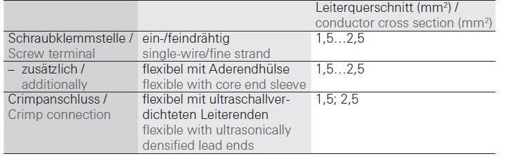
TGL-Basic                                                      Montageanleitung

       Sicherheitshinweise
        Diese Anleitung setzt Fachkenntnisse voraus, die einer abgeschlossenen
        Berufsausbildung im Elektrohandwerk entsprechen!
        •     Arbeiten Sie niemals bei anliegender Spannung an der Leuchte.
              Vorsicht-Lebensgefahr!
        •     Bei Störungen des LED-Moduls wenden Sie sich bitte an AS LED Lighting zum Austausch der Module.
        •     Leitungen nicht auf die Leuchte legen.
        •     Für die Installation und für den Betrieb der Leuchten sind die nationalen Sicherheitsvorschriften zu beachten.
        Wichtige Hinweise zu elektronischen Betriebsgeräten (EVG)
        •     Eine Neutralleiterunterbrechung im Drehstromkreis führt zu Überspannungsschäden in der Beleuchtungsanlage. Neutralleiter – Trennklemme
              deshalb nur spannungsfrei öffnen und vor Wiedereinschalten schließen.
        •     Die maximal zulässige Umgebungstemperatur ta der Leuchte darf nicht überschritten werden. Überschreitung reduziert die Lebensdauer, im
              Extremfall droht Frühausfall.
        •     Anschlussleitungen für Steuereingänge dimmbarer EVG (1-10V, Dali, etc.) 230V netzspannungsfest auslegen.

        Safety notes
        These instructions assume expert knowledge corresponding to a completed professional education as an electrician.
        •     Never work when voltage is present on the luminaire.
              Caution – Risk of fatal injury!
        •     In case of malfunctions with the LED module, please contact us, changing the modules.
        •     Do not place any cables on the luminaire.
        •     Please note national safety instructions for installation and operation of this luminaire.
        Important Information Regarding Electronic Control Gear (ECG)
        •     Interference to the neutral conductor in a three-phase system may result in surge-related damage in the lighting installation. Only open neutral
              conductor –disconnect terminal when disconnected from power supply and close prior to switching back on.
        •     The maximum admissible ambient temperature ta of the luminaire may not be exceeded. Surpassing that temperature reduces the service life
              and, in extreme cases, poses risk of early failure.
        •     Use mains cables for control inputs of dimmable ECG (1-10V, Dali, etc.) which are rated for 230V.

        Bestimmungsgemäße Verwendung
        •     Die Leuchte TGL ist für Aussenbereiche und Feuchträume mit der
        •     Umgebungstemperatur von -25°C bis +50°C bestimmt.
        •     Die Tragfähigkeit der Decke muss durch bauseitige Maßnahmen sichergestellt sein.
        •     Technische Änderungen behält sich die AS LED Lighting GmbH vor.
        •     Der Hersteller übernimmt keine Haftung für Schäden, die durch unsachgemäßen Einsatz entstehen.
        •     Die Lichtquelle/Batterie dieser Leuchte darf nur vom Hersteller oder einem von ihm beauftragten Servicetechniker oder einer vergleichbaren
              Fachkraft ersetzt werden.

        Intended use
        •     The TGL luminaire is intended for outdoor applications and wet rooms at an ambient temperature of -25°C to +50°C.
        •     The ceiling carrying capacity must be secured by appropriate building measures.
        •     Further modification for technical specification only by AS LED Lighting GmbH.
        •     The manufacturer bears no liability for damage caused by inappropriate use or application.
        •     The light source and battery of this luminaire may only be replaced by the manufacturer or by a service technician appointed by him or a
              comparable specialist.

https://www.as-led.de/                                    Seite 1 von 10                                                                  Rev. 16.07.2021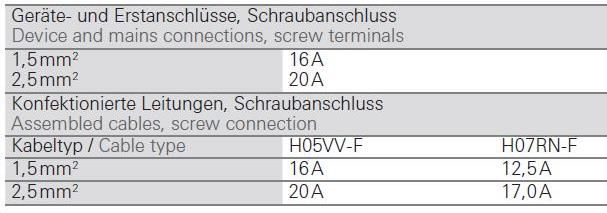
TGL-Basic                                                Montageanleitung
 Leuchten Typen
 Luminaire types
                                                                        L           B         H
                                Modellbezeichnung
                                                                      (mm)        (mm)      (mm)
             TGL-030010-xxx-01-MLH/MLD(-DALI)                         409         102        93
             TGL-030010-xxx-01-MLH/MLD(-DALI)-opal                    409         102        93
             TGL-060010-xxx-02-MLH/MLD(-DALI)                         689         102        93
             TGL-060010-xxx-02-MLH/MLD(-DALI)-opal                    689         102        93
             TGL-090010-xxx-03-MLH/MLD(-DALI)                         969         102        93
             TGL-090010-xxx-03-MLH/MLD(-DALI)-opal                    969         102        93
             TGL-120010-xxx-04-MLH/MLD(-DALI)                         1249        102        93
             TGL-120010-xxx-04-MLH/MLD(-DALI)-opal                    1249        102        93
             TGL-150010-xxx-05-MLH/MLD(-DALI)                         1529        102        93
             TGL-150010-xxx-05-MLH/MLD(-DALI)-opal                    1529        102        93
             xxx=830/840/850/865

 Lieferumfang
 scope of delivery
 https://www.as-led.de/

                                                                             2x       Befestigunsflansch (Beipack)
                                                                                     mounting flange (accessory pack)

                                                    4x
                                           Senkkopfschraube M5x14 Torx (Beipack)
                                           countersunk head screw (accessory pack)
                                                                                           Linsen-Blechschrauben
                                                                                               DIN7981 TORX
                      1x                                                                          C 3,5x19
            TGL Dichtung                                                          4x      Pan head tapping screws
       Seitendeckel 3mm mit                                                                    DIN7981 TORX
          Klebefolie weiß,                                                                        C 3,5x19
        werksseitig montiert
        TGL gasket side cover
       3mm with adhesive foil                                                                     TGL Druckausgleichselement
               white,                                                                              M12, werkseitig montiert
          factory-mounted                                                                         TGL pressure compensation
                                                                                                    element M12, factory-
                                                                                                           mounted
                                                    1x                                                     1x
                            TGL Seitendeckel Rev.5-1, 1xM12-
                             1xM20, ohne Verdrehsicherung
                          TGL side cover Rev.5-1, 1xM12-1xM20,                                                  2x
                                 without twist protection
                                                                                IP-65 Verschraubung Click M20 (1x
                                                                                 werkseitig montiert, 1x Beipack)
                                                                              IP-65 cable gland Click M20 (1x factory
                                                                                     fitted, 1x accessory pack)

https://www.as-led.de/                               Seite 2 von 10                                             Rev. 16.07.2021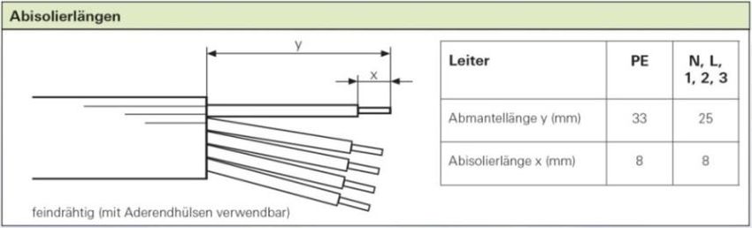
TGL-Basic                                       Montageanleitung
 Abmessungen und Vorbereitung
 Dimensions and Preparation
                                    Bohrungsmaße TGL
                                                                  Abstand     Max.      Min.
                                                                                                Länge   Länge
                                     Typ                          Bohrung   Bohrmaß   Bohrmaß
                                                                                                 [L1]     [L]
                                                                    [A]        [D]       [C]
                   TGL-030010                                       375        385       360     365     409
                   TGL-060010                                       655        665       640     645     689
                   TGL-090010                                       935        945       920     925     969
                   TGL-120010                                      1215       1225      1200    1205    1249
                   TGL-150010                                      1495       1505      1480    1485    1529

 Montage Befestigungsflansch
 Attach the mounting flange

                                2
                                              Befestigungsflansch auf Leuchte schrauben.
                                              Screw the mounting flange on the luminaire.

               1

                                                                                                        1

https://www.as-led.de/                      Seite 3 von 10                                                     Rev. 16.07.2021
TGL-Basic                                                 Montageanleitung
 Decke bohren                                                 Montage Dübel
 Drill the ceiling                                            Drill the ceiling

                                                                                               A
                               A

                      1                                                                  2                     2
                                                  1
                                                                    Dübel und/oder Schrauben für die Deckenmontage
                                                                            nicht im Lieferumfang enthalten.
      Abstand Bohrung A siehe Bild 4 und 5 aus Seite 3.
                                                                      Dowels and/or screws for ceiling mounting are
       Find dimension A in picture 4 and 5 on page 3.
                                                                               not included in the delivery.

 Deckenmontage
 Mounting on ceiling

              1                                                     A
                                                                    1

                                                                                                              1

                2

                                                                                                               2
                                         Abstand Bohrung A siehe Bild 4 und 5 aus Seite 3.
                                          Find dimension A in picture 4 and 5 on page 3.

https://www.as-led.de/                             Seite 4 von 10                                                     Rev. 16.07.2021
TGL-Basic Montageanleitung
Lösen der Erdschraube (Torx10) Netzteileinheit herausziehen
Unscrew and remove the electrical Pull out the Power Supply
ground connection
1
2
Achtung: Die Zahnscheibe und M3x6 Schraube
aufbewahren! Netzteileinheit aus der Leuchte herausziehen
Warning: Keep the lock washer and M3x6 bis die Anschlußklemme (5 polig) frei
screw! zugänglich ist.
Pull out the Power Supply Unit until the cage
clamp (5-pole) is free to use.
Anschlußkabel anschließen Erdschraube mit Zahnscheibe einschrauben
Connect cabel (Torx T10)
Screw in the ground connection screw with lock
washer
Achtung: Handfest anziehen! Mit
Anschlußkabel gemäß VDE-Installationsvorschrift an
Akkuschrauber max. Stufe 3.
der Klemme anklemmen
Warning: Hand screwed! With electric
Connect cabel to cage clamp according to VDE-
drill moment of force maximum is 3!
Standards
https://www.as-led.de/ Seite 5 von 10 Rev. 16.07.2021TGL-Basic Montageanleitung
Netzteileinheit in die Leuchte wieder Seitendeckel montieren
zurückschieben Side cap mounting
Move back the power supply unit
1
2
3 4
Seitendeckel auf den Leuchtenkorpus von oben nach unten schieben bis er über das
Profil rutscht. Anschliessend mit den 4 Blechschrauben (3,5x19) anschrauben.
Darauf achten, dass die Scheibe sauber unter dem überstehenden Rand des
Seitendeckels rutscht. Eventuell mit dem Finger die Scheibe unter den Deckel drücken.
Zusätzlich darauf achten, dass die innenliegende Dichtung sauber im Seitendeckel liegt
und nicht unter die Scheibe verrutscht ist.
Push the side cover onto the luminaire body from top to bottom until it slides over the
profile. Then screw on with the 4 self-tapping screws (3.5x19).
Make sure that the pane slides cleanly under the projecting edge of the side cover. If
necessary, press the pane under the cover with your finger. In addition, make sure that
the inner seal lies neatly in the side cover and has not slipped under the disc.
IP-Verschraubung aufsetzen
Screw in the IP Connector
Aussenschraube der IP-Verschraubung aufsetzen und fest
anziehen bis die Verbindung dicht ist.
Screw in the IP Connector nut till the connection is sealed.
Durchverdrahtung
Electrical wiring through luminaire
Bei dieser Leuchte kann die Durchverdrahtung sowohl auf einer Seite gemacht werden, wie auch auf beiden Seiten.
With this luminaire you can realize an electrical wiring through the luminaire in two ways, one is to make the wiring on one
side, the other way is to make an electrical wiring through the luminaire on both sides.
https://www.as-led.de/ Seite 6 von 10 Rev. 16.07.2021TGL-Basic Montageanleitung
Durchverdrahtung einseitig Durchverdrahtung zweiseitig
Electrical wiring on one side Electrical wiring on both sides
Mit einem Kegelbohrer das Logo für eine M20-Verschraubung Am Seitendeckeln an einem der Logos ein Loch für M20-
ausschneiden. Die mitgelieferte IP-Verschraubung einsetzen und Verschraubungen mit einem Kegelbohrer ausschneiden. Die
verschrauben. mitgelieferte IP-Verschraubung einsetzen und verschrauben.
Darauf achten, dass die innenliegende Dichtung sauber auf dem Darauf achten, dass die innenliegende Dichtung sauber auf dem
Deckel aufliegt. Deckel aufliegt.
Das zweite Kabel durch die IP-Verschraubung ziehen wie unter Das zweite Kabel durch die IP-Verschraubung ziehen und durch
Schritt 2 beschrieben. die Leuchte durchschieben, bis die Anschlüsse bis zur WAGO-
Das Kabel nach VDE-Vorschrift in den 2.ten Polen der WAGO- Klemme reichen.
Klemme befestigen. Seitlich im Gehäuse ist dazu eine Führungsrinne für das Kabel
Drill with a step drill an M20 hole at the AS-logo from inside the vorgesehen, in der das Kabel durchgeführt werden kann.
side cap for the IP connector. After mounting the IP connector Das Kabel nach VDE-Vorschrift in den 2.ten Polen der WAGO-
look at the proper function of the seal inside the side cap. Move Klemme befestigen.
the second cable through the IP connector as described in step 2. Drill with a step drill an M20 hole at the AS-logo from inside the
Connect the second cable according to VDE standards. side cap for the IP connector. After mounting the IP connector
look at the proper function of the seal inside the side cap. Move
1 the second cable through the IP connector as described in step 2
but move the cable through the luminaire body till the cable
comes out at the WAGO cable clamp side. At the side of the
luminaire body is a guide rail for the cable.
Connect the cable into the second poles of the WAGO clamp
according to VDE standards.
.
1
2
3 2
3
4
4
5
5
https://www.as-led.de/ Seite 7 von 10 Rev. 16.07.2021TGL-Basic Montageanleitung Anschlußbelegung (3-polig) Anschlußbelegung (3-polig) Pin assignments of the socket (3-pole) Pin assignments of the socket (3-pole) Belegung Kabel Phase L Braun Neutralleiter N Blau GND PE Grün/Gelb Anschlußbelegung (5-polig) Anschlußbelegung (5-polig) Pin assignments of the socket (5-pole) Pin assignments of the socket (5-pole) Belegung Kabel Phase L1 L Braun Neutralleiter N Blau GND PE Grün/Gelb DALI DA1 Grau DALI DA2 Schwarz Technische Spezifikationen Anschließbare Leiterarten Technical specifications Type of conductors which can be connected Anschließbare Querschnitte (mm²) Bemessungsstrom Connectable cross sections (mm²) Rated current https://www.as-led.de/ Seite 8 von 10 Rev. 16.07.2021
TGL-Basic                                                 Montageanleitung

  Sicherungsautomat              C10        C13         C16       C20       B10       B13       B16       B20         Einschaltstrom

           Installation Ø      1,5 mm²    1,5 mm²      2,5 mm²   2,5 mm²   1,5 mm²   1,5 mm²   2,5 mm²   2,5 mm²    Imax       Pulsdauer

  Anzahl Leuchten:
  TGL-030010-01-MLH              40         56           64        80        24        31        38        48       14A          280μs
  TGL-030010-01-MLH-DALI         40         56           64        80        24        31        38        48       16A          255μs
  TGL-030010-01-MLD              31         41           51        70        19        25        31        42       28A          139µs
  TGL-030010-01-MLD-DALI         31         43           53        66        19        26        32        40       26A          151µs
  TGL-060010-02-MLH              35         50           60        76        23        30        36        46       21A          126µs
  TGL-060010-02-MLH-DALI         30         38           46        58        18        23        28        35      13,6A         304µs
  TGL-060010-02-MLD              16         21           26        35        10        13        16        21       32A          240µs
  TGL-060010-02-MLD-DALI         21         28           36        45        13        17        22        27      22,4A         176µs
  TGL-090010-03-MLH              35         50           60        76        23        30        36        46       21A          126µs
  TGL-090010-03-MLH-DALI         30         38           46        58        18        23        28        35      13,6A         304µs
  TGL-090010-03-MLD              16         21           26        35        10        13        16        21       32A          240µs
  TGL-090010-03-MLD-DALI         21         28           36        45        13        17        22        27      22,4A         176µs
  TGL-120010-04-MLH              16         21           26        35        10        13        16        21       32A          240µs
  TGL-120010-04-MLH-DALI         21         28           36        45        13        17        22        27      22,4A         176µs
  TGL-120010-04-MLD              16         21           26        35        10        13        16        21       30A          253µs
  TGL-120010-04-MLD-DALI         21         28           35        45        13        17        21        27       23A          174µs
  TGL-120010-04-MLH-HT           33         41           53        66        20        25        32        40       5,0A        1000µs
  TGL-120010-04-MLH-DALI-HT      25         32           41        50        15        19        24        30       20A          216µs
  TGL-120010-04-MLD-HT           33         41           53        66        20        25        32        40       5,0A        1000µs
  TGL-120010-04-MLD-DALI-HT      25         32           41        50        15        19        24        30       23A          194µs
  TGL-150010-05-MLH              16         21           26        35        10        13        16        21       32A          240µs
  TGL-150010-05-MLH-DALI         21         28           36        45        13        17        22        27      22,4A         176µs
  TGL-150010-05-MLD              16         21           26        35        10        13        16        21       30A          253µs
  TGL-150010-05-MLD-DALI         21         28           35        45        13        17        21        27       23A          174µs
  TGL-150010-05-MLH-HT           33         41           53        66        20        25        32        40       5,0A        1000µs
  TGL-150010-05-MLH-DALI-HT      25         32           41        50        15        19        24        30       20A          216µs
  TGL-150010-05-MLD-HT           33         41           53        66        20        25        32        40       5,0A        1000µs
  TGL-150010-05-MLD-DALI-HT      25         32           41        50        15        19        24        30       23A          194µs
 Tabelle gilt für transparente und opale Ausführung.
 The table applies to transparent and opal versions.

https://www.as-led.de/                              Seite 9 von 10                                                         Rev. 16.07.2021
TGL-Basic Montageanleitung
Installationshinweis
Installation information
Die Lichtquelle/die Module dieser Leuchte sind austauschbar. Wenn die Lichtquelle ihr Lebensdauerende erreicht hat, können die Module ersetzt
werden. Die Lichtquelle dieser Leuchte darf nur vom Hersteller oder einem von ihm beauftragten Servicetechniker oder einer vergleichbaren
Fachkraft ersetzt werden.
The luminaire light source (s) are interchangeable. When the light source has reached its end of life, the modules can be replaced. The light source
of this luminaire may only be replaced by the manufacturer or by a service technician appointed by him or a comparable specialist.
“Vorsicht, Gefahr des elektrischen Schlags!”
Achtung, gefährliche Spannung > 65Vdc!
Arbeiten an der Leuchte dürfen nur im spannungslosen Zustand durchgeführt werden und
setzen Fachkenntnisse voraus, die einer abgeschlossenen Berufsausbildung im Elektrohandwerk entsprechen!
„Caution, risk of electric shock“
Caution, dangerous voltage> 65Vdc!
Work on the luminaire must only be carried out in a tension - free state.
These instructions assume expert knowledge corresponding to a completed professional education as an electrician.
Nicht zur Abdeckung mit Wärmedämm-Material geeignete Leuchte.
Not suitable for covering with heat-insulating material.
Das Symbol der durchgestrichenen Mülltonne auf Rädern bedeutet, dass das Produkt in der EG einer getrennten Müllsammlung zugeführt
werden muss. Dies gilt für das Produkt und alle mit diesem Symbol gekennzeichneten Zubehörteile. Gekennzeichnete Produkte dürfen nicht
über den normalen Hausmüll entsorgt werden, sondern müssen einer Annahmestelle für das Recycling von elektrischen und elektronischen
Geräte entsorgt werden.
The symbol of the crossed-out wheeled bin means that the product must be sent to a separate waste collection point in the EC. This applies to the
product and all accessories marked with this symbol. Marked products may not be disposed of with normal household waste, but must be disposed
of at a collection point for the recycling of electrical and electronic equipment.
Für die Anwendung diverser Zubehöre sowie weitere Hinweise für die Installation in Aussenbereichen finden Sie weiter Hinweise auf der Homepage des
Herstellers unter:
For using diverse accessories and finding further information for outdoor installations go to the manufacturer homepage at:
https://eshop.wieland-electric.com/wielandCategories
https://www.as-led.de/ Seite 10 von 10 Rev. 16.07.2021Sie können auch lesen