MONTAGEANLEITUNG INSTALLATION GUIDE - tempLED RayProof V2
←
→
Transkription von Seiteninhalten
Wenn Ihr Browser die Seite nicht korrekt rendert, bitte, lesen Sie den Inhalt der Seite unten

MONTAGEANLEITUNG
INSTALLATION GUIDE

tempLED RayProof V2

                     tempLED GmbH
                       V.01/2020
MONTAGEANLEITUNG                                                           INSTALLATION GUIDE

tempLED RayProof V2 Serie                                                  tempLED RayProof V2 series
Allgemeine Sicherheitshinweise                                             General safety notes
                                                             1
Vorsicht!                                                                  Caution!
Gefahr eines elektrischen Schlages!                                        Risk of electric shock!

Montage und Inbetriebnahme der Leuchte nur                                 Mounting and installation of the luminaire only by
durch autorisierte Fachkräfte. Vor jeder Arbeit                            authorized personnel. Disconnect the power sup-
an der Leuchte die Stromzufuhr unterbrechen                                ply and protect it from restart by mistake before
und gegen versehentliches Wiedereinschalten                                working on the luminaire. The luminaire must
sichern. Die Leuchte darf nur mit vollständigem                            only be operated with complete and undam-
und unbeschädigtem Gehäuse in Betrieb genom-                               aged housing. Please secure the main power
men werden. Die Stromzufuhr ist mit geeigneten                             by means of suitable measures, for example a
Maßnahmen (Fehlerstrom-Schutzschalter o.ä.)                                residual current circuit breaker.
abzusichern.

                                                             2
Vorsicht!                                                                  Caution!
Absturzgefahr!                                                             Danger of falling!

Bei der Montage der Leuchte ist darauf zu                                  Please use suitable mounting material (screws,
achten, dass das gewählte Montagematerial                                  wall plugs) and dimensions for the drilling holes
(Schrauben, Dübel) sowie die Dimensionen von                               and screws. They must be suitable for the weight
Bohrlöchern und Schrauben für das Gewicht der                              of the luminaire as well as the composition and
Leuchte und die Beschaffenheit und Tragfähig-                              bearing capacity of the mounting location. No
keit der Montageoberfläche geeignet ist.                                   liability for damages resulting from improper
Keine Haftung für fehlerhaft ausgeführte Monta-                            installation, inexpert operation or modification of
ge, unsachgemäßen Betrieb oder Veränderun-                                 the luminaire!
gen an der Leuchte!

                                                             3
Lieferumfang:                                                                        Package contents:

- Leuchte der RayProof V2-Serie                                                      - RayProof V2 luminaire
- Diffusor (1x)                                                                      - Diffuser (1x)
- Wandhalter (2x)                                                                    - Wall mounting brackets (2x)
- Gummidichtring (1x)                                                                - Rubber sealing ring (1x)
- Sicherungsschrauben (4x)                                                           - Security screws (4x)
- Schnellverschluss:                                                                 - Quick-release fasteners:
  6x bei Leuchtenbaulänge 655 mm                                                       6x for luminaire length 655 mm
  14x bei Leuchtenbaulänge 1.560 mm                                                    14x for luminaire length 1,560 mm
  16x bei Leuchtenbaulänge 1.860 mm                                                    16x for luminaire length 1,860 mm

                          © tempLED GmbH | Marmorwerkstraße 52 | 83088 Kiefersfelden | Deutschland
                              info@tempLED.de | www.tempLED.de | WEEE-Reg.-Nr.: DE 26163456

                                                         V.01/2020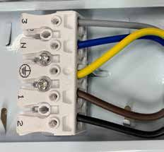
MONTAGEANLEITUNG INSTALLATION GUIDE
tempLED RayProof V2 Serie tempLED RayProof V2 series
Wand- / Deckenmontage Surface mounting
1
Schritt 1: Step 1:
Anzeichnen der Bohrlöcher 14 mm
Marking the drill holes
Zeichnen Sie die Bohrlöcher an der Mark the drill holes on the surface of
Oberfläche des Montageortes an. the mounting location. Please use the
Nehmen Sie dazu die nebenstehende measurement drawing on the left.
55 mm
26 mm
15 mm
Masszeichnung zur Hilfe.
7 mm
4 mm 6 mm
2
Schritt 2: Step 2:
Abstand der Wandhalter Distance between the wall mounting
brackets
360 mm / 1.200 mm / 985 mm
Wandhalterabstand:
bei Leuchtenbaulänge 655mm:
360 mm
Der Abstand der beiden Wandhalter bei Leuchtenbaulänge 1.560 mm:
1.200 mm
The distance of the two wall mounting
zueinander beträgt: bei Leuchtenbaulänge 1.860 mm:
985 mm brackets is:
Bei der Leuchtenbaulänge 655 mm: ========================================
For luminaire housing length 655 mm:
Distance between wall mounting brackets:
360 mm. for luminaire housing length 655mm: 360 mm.
360 mm
Bei der Leuchtenbaulänge 1.560 mm: for luminaire housing length 1,560 mm:
1,200 mm
For luminaire housing length 1,560 mm:
1.200 mm. for luminaire housing length: 1,860 mm:
985 mm
1,200 mm.
Bei der Leuchtenbaulänge 1.860 mm: For luminaire housing length 1,860 mm:
985 mm. 985 mm.
3
Schritt 3: Step 3:
Bohrlöcher anfertigen Drilling the holes
Prüfen Sie ggf. die Stellen der Bohrlö- Please check the drilling spots with a
cher mit einem Leitungssuchgerät und line locator and drill the holes. Choose
fertigen Sie dann die Bohrlöcher an. a drill hole diameter suitable for the
Wählen Sie einen der Montageober- material of the mounting surface and
fläche und dem Gewicht der Leuchte the weight of the luminaire.
angepassten Bohrlochdurchmesser. (symbol illustration)
(Symbolabbildung) Leit
un
ON
/O
FF
g
Lin ssuc
e lo hg
cat erät
or
Driller icon made by Freepik from www.flaticon.com
© tempLED GmbH | Marmorwerkstraße 52 | 83088 Kiefersfelden | Deutschland
info@tempLED.de | www.tempLED.de | WEEE-Reg.-Nr.: DE 26163456
V.01/2020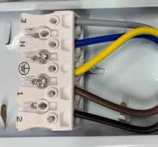
MONTAGEANLEITUNG                                                                      INSTALLATION GUIDE

tempLED RayProof V2 Serie                                                             tempLED RayProof V2 series
Wand- / Deckenmontage                                                                 Surface mounting
                                                              4
Schritt 4:                                                                            Step 4:
Montieren der Wandhalter                                                              Mounting the brackets

Montieren Sie die beiden Wandhalter                                                   Screw the two wall mounting brackets
in den in Schritt 2 dargestellten Ab-                                                 to the surface in the distance shown in
ständen voneinander mit geeignetem                                                    step 2. Use screw material suitable for
Schraubenmaterial für die Montageob-                                                  the mounting surface and the weight
erfläche und dem Gewicht der Leuchte.                                                 of the luminaire. We recommend
Wir empfehlen den Einsatz von Edel-                                                   high-grade steel screws and mounting
stahlschrauben.                                                                       material.

                                                              5
Schritt 5:                                                                            Step 5:
Montieren der Leuchte                                                 CLICK!          Mounting the luminaire

Clipsen Sie das graue Gehäuseun-                                                      Clip the grey housing bottom of the
terteil der tempLED RayProof auf die                                                  tempLED RayProof onto the two wall
beiden Wandhalter links und rechts auf.                                               mounting bracktes on the left and on
                                                                                      the right side.

                                                              6
Schritt 6:                                                                            Step 6:
Abnehmen des LED-Lichtfelds 1                                                         Removing the led light field 1

Nehmen Sie das LED-Lichtfeld links                                                    Remove the LED light field from the
aus dem grauen Gehäuseunterteil in                                                    grey housing bottom on the left side by
dem Sie gleichzeitig die beiden Halte-                                                pressing the two retaining clips [1] and
                                                                         1
klammern [1] zusammendrücken und                                                      simultaneously using the grip [2] to pull
das LED-Lichtfeld am Griff [2] heraus-                                                out the LED light field.
                                              2
ziehen.
Das LED-Lichtfeld ist mit zwei Fang-                                                  The LED light field is secured by two
bändern gesichert.                                                                    catch straps.

                           © tempLED GmbH | Marmorwerkstraße 52 | 83088 Kiefersfelden | Deutschland
                               info@tempLED.de | www.tempLED.de | WEEE-Reg.-Nr.: DE 26163456

                                                          V.01/2020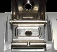
MONTAGEANLEITUNG INSTALLATION GUIDE
tempLED RayProof V2 Serie tempLED RayProof V2 series
Wand- /Deckenmontage / Elektrik Surface mounting / electrical
7
Schritt 7: Step 7:
Abnehmen des LED-Lichtfelds 2 Removing the led light field 2
Nehmen Sie das LED-Lichtfeld rechts Remove the LED light field from the
aus dem grauen Gehäuseunterteil in grey housing bottom on the right side
dem Sie gleichzeitig die beiden Halte- by pressing the two retaining clips [1]
klammern [1] zusammendrücken und and simultaneously using the grip [2] to
das LED-Lichtfeld am Griff [2] heraus- 1 2 pull out the LED light field.
ziehen.
Das LED-Lichtfeld ist mit zwei Fang- The LED light field is secured by two
bändern gesichert. catch straps.
8
Schritt 8: Step 8:
Vorbereiten der PG-Verschraubung Preparing the cable nut
Schrauben Sie die Mutter der PG- Unscrew the nut from the PG
Verschraubung, die Sie als Eingang connection you choosed to use. Be
nutzen möchten, ab. Achten Sie darauf, careful not to lose the black rubber
dass der schwarze Dichtring nicht sealing ring.
verloren geht.
9
Schritt 9: Step 9:
Zweite PG-Verschraubung abdichten Sealing second PG connection
Sofern Sie die Durchgangsverdrahtung If you do not use through-wiring, please
nicht nutzen, dichten Sie die zweite be sure to seal the second PG connec-
PG-Verschraubung auf der gegenüber- tion at the opposite end properly.
liegenden Seite fachgerecht ab.
© tempLED GmbH | Marmorwerkstraße 52 | 83088 Kiefersfelden | Deutschland
info@tempLED.de | www.tempLED.de | WEEE-Reg.-Nr.: DE 26163456
V.01/2020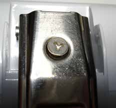
MONTAGEANLEITUNG INSTALLATION GUIDE
tempLED RayProof V2 Serie tempLED RayProof V2 series
Elektrischer Anschluss Electric power connection
10
Schritt 10: Step 10:
Netzkabel einführen Feeding in the power cable
Fädeln Sie die Mutter und je nach Thread the nut and, depending on
Kabeldurchmesser auch den schwar- the cable diameter, also the black
zen Dichtring auf das Netzkabel auf sealing ring onto the power cable and
und führen Sie das Netzkabel durch die feed the power cable through the PG
PG-Verschraubung. connection.
Hinweis: das dickere Ende des schwar- Please note: The thicker end of the
zen Dichtrings muss nach innen black rubber sealing ring has to point
zeigen. towards the inner side of the luminaire.
11
Schritt 11: Durchgangsverdrahtung / through-wiring Step 11:
Klemmblockbelegung Terminal block wiring
Verbinden Sie das Netzkabel mit dem Connect the power cable to the ter-
Klemmenblock auf der Rückseite des minal block on the backside of the LED
LED-Lichtfeldes gemäß der Beschrif- light field according to the labeling on
tung auf dem Klemmenblock: 3 N 1 2 the terminal block:
Phase [1] - braun Power conductor [1] - brown
Schutzleiter (Erdung) - gelb/grün Protective conductor - yellow/green
Neutralleiter [N] - blau Neutral conductor [N] - blue
Zusatzleiter [2/3] - schwarz/grau Additional conductors [2/3] - black/grey
12
Schritt 12: Step 12:
Netzkabel verbinden Power connection
Drücken Sie den entsprechenden He- Push down the respective lever on the
bel am Klemmblock herunter, stecken terminal block, insert the cable wire
Sie die Kabelader bis zum Anschlag ein fully and release the lever again.
und lassen den Hebel wieder los.
Prüfen Sie anschließend den festen Check if the cable wire is seated se-
Sitz der Kabelader. curely.
Wiederholen Sie die Schritte für alle Repeat the steps for all cable wires.
notwendigen Kabeladern.
© tempLED GmbH | Marmorwerkstraße 52 | 83088 Kiefersfelden | Deutschland
info@tempLED.de | www.tempLED.de | WEEE-Reg.-Nr.: DE 26163456
V.01/2020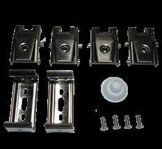
MONTAGEANLEITUNG INSTALLATION GUIDE
tempLED RayProof V2 Serie tempLED RayProof V2 series
Elektrik / Diffusormontage Electrical / diffusor mounting
13
Schritt 13: Step 13:
LED-Lichtfeld einbauen Re-inserting the LED light field
CLICK!
Setzen Sie das LED-Lichtfeld wieder Re-insert the LED light field into the
zurück in das graue Gehäuseunterteil, grey housing bottom until the two pairs
bis die beiden Halteklammernpaare of retaining clips on the left and on the
links und rechts einrasten und das right engage and the LED light field is
LED-Lichtfeld fest sitzt. secured.
Achtung! Achten Sie darauf, dass Caution! Be sure not to pinch cables or
weder Kabel noch Fangbänder einge- catch straps.
klemmt werden.
14
Schritt 14: Step 14:
PG-Verschraubung verschließen Closing PG screw connection
Ziehen Sie das Netzkabel vorsichtig Carefully push back the power cable
etwas aus dem Leuchtengehäuse und somewhat from the luminaire housing
verschließen Sie die PG-Verschrau- and close the PG connection. Be sure
bung. Achten Sie darauf, dass der that the black rubber sealing ring fits
schwarze Gummidichtring sauber sitzt properly and is not pinched.
und sich nicht verklemmt.
15
Schritt 15: Step 15:
Schnellverschlüsse einclipsen 1 Clipping on the quick-release
fasteners 1
Clipsen Sie die 14 bzw. 16 Schnellver- Clip the 14 or 16 quick-release fasten-
schlüsse auf beiden Seiten des grauen ers onto the grey housing bottom as
Gehäuseunterteils ein. shown to the left.
© tempLED GmbH | Marmorwerkstraße 52 | 83088 Kiefersfelden | Deutschland
info@tempLED.de | www.tempLED.de | WEEE-Reg.-Nr.: DE 26163456
V.01/2020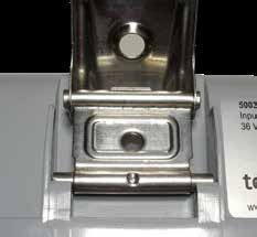
MONTAGEANLEITUNG INSTALLATION GUIDE
tempLED RayProof V2 Serie tempLED RayProof V2 series
Diffusormontage Diffusor mounting
16
Schritt 16: Step 16:
Schnellverschlüsse einclipsen 2 CLICK! CLICK! Clipping on the quick-release
fasteners 2
Achten Sie darauf, dass die Schnell- Make sure that the quick-release
verschlüsse mit ihren Zapfen links fasteners with their stoppers on the left
und rechts mit zwei deutlich hörbaren and on the right engage properly (you
CLICKs sauber einrasten und parallel should hear two CLICK sounds) and sit
zum Gehäuse sitzen. parallel to the luminaire housing.
17
Schritt 17: Step 17:
Diffusor aufsetzen Setting the diffuser
Setzen Sie die den Diffusor auf das Set the diffuser onto the grey housing
graue Gehäuseunterteil und achten bottom and make sure that the all-
Sie auf sauberen Sitz der umlaufenden round seal fits properly.
Dichtung.
18
Schritt 18: Step 18:
Schnellverschlüsse schließen Closing quick-release fasteners
Schließen Sie alle Schnellverschlüsse One after the other, close all
der Reihe nach. quick-release fasteners.
Achten Sie darauf, dass die Schnell- Be careful that the quick-release
CLICK!
verschlüsse sauber und gerade in den fasteners engage properly and straight
Diffusor greifen. with the cover.
© tempLED GmbH | Marmorwerkstraße 52 | 83088 Kiefersfelden | Deutschland
info@tempLED.de | www.tempLED.de | WEEE-Reg.-Nr.: DE 26163456
V.01/2020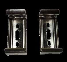
MONTAGEANLEITUNG                                                                      INSTALLATION GUIDE

tempLED RayProof V2 Serie                                                             tempLED RayProof V2 series
Diffusormontage                                                                       Diffusor mounting
                                                             19
Schritt 19:                                                                           Step 19:
Sitz der Absturzsicherung                                                             Location of safety catch

Am Diffusor sitzen je eine integrierte                                                The diffuser has two integrated safety
Absturzsicherung für den Diffusor am                                                  catches. They are located at the left
jeweils linken und rechten Ende inner-                                                and right end of the diffuser within
halb der Haltenasen für die Schnellver-                                               the retaining lugs of the quick-release
schlüsse.                                                                             fasteners.

                                                             20
Schritt 20:                                                                           Step 20:
Absturzsicherung kontrollieren                                                        Control safety catch

Kontrollieren Sie die beiden Absturzsi-                                               Control the two safety catches of the
cherungen des Diffusors. Der jeweilige                                                diffuser. The respective quick-release
Schnellverschluss muss sauber unter-                                                  fastener has to be engaged properly
halb des Dreiecks eingerastet sein.                                                   below the triangle.

                                                             21
Schritt 21:                                                                           Step 21:
Sicherheitsschrauben einsetzen                                                        Insert security screws

Wenn Sie die tempLED RayProof                                                         If you want to secure the tempLED
V2 gegen unbefugtes Öffnen sichern                                                    RayProof V2 against unauthorized
möchten, verwenden Sie die mitgelie-                                                  opening, please use the security
ferten Sicherheitsschrauben.                                                          screws supplied.

                           © tempLED GmbH | Marmorwerkstraße 52 | 83088 Kiefersfelden | Deutschland
                               info@tempLED.de | www.tempLED.de | WEEE-Reg.-Nr.: DE 26163456

                                                          V.01/2020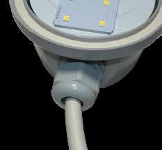
MONTAGEANLEITUNG INSTALLATION GUIDE
tempLED RayProof V2 Serie tempLED RayProof V2 series
Durchgangsverdrahtung Through-wiring
1
Schritt 1: Step 1:
Vorbereiten der PG-Verschraubung Preparing the cable nuts
Schrauben Sie die Mutter der PG- Unscrew the nut from the PG
Verschraubung ab. Achten Sie darauf, connection. Be careful not to lose the
dass der schwarze Dichtring nicht black rubber sealing ring.
verloren geht.
Wiederholen Sie den Schritt für die Repeat the step for the second PG
zweite PG-Verschraubung auf der connection at the opposite.
gegenüberliegenden Seite.
Die RayProof V2 ist serienmäßig mit The RayProof V2 luminaire has
Durchgangsverdrahtung ausgestattet. through-wiring ex works.
2
Schritt 2: Step 2:
Netzkabel einführen Feeding in the power cable
Fädeln Sie die Mutter und je nach Thread the nut and, depending on
Kabeldurchmesser auch den schwar- the cable diameter, also the black
zen Dichtring auf das Netzkabel auf sealing ring onto the power cable and
und führen Sie das Netzkabel durch die feed the power cable through the PG
PG-Verschraubung. connection.
Hinweis: das dickere Ende des schwar- Please note: The thicker end of the
zen Dichtrings muss nach innen black rubber sealing ring has to point
zeigen. towards the inner side of the luminaire.
3
Schritt 3: Step 3:
Netzkabel ausführen Feeding out the power cable
Fädeln Sie die Mutter und je nach Thread the nut and, depending on
Kabeldurchmesser auch den schwar- the cable diameter, also the black
zen Dichtring auf das Netzkabel auf sealing ring onto the power cable and
und führen Sie das Netzkabel durch die feed the power cable through the PG
PG-Verschraubung. connection.
Hinweis: das dickere Ende des schwar- Please note: The thicker end of the
zen Dichtrings muss nach innen black rubber sealing ring has to point
zeigen. towards the inner side of the luminaire.
© tempLED GmbH | Marmorwerkstraße 52 | 83088 Kiefersfelden | Deutschland
info@tempLED.de | www.tempLED.de | WEEE-Reg.-Nr.: DE 26163456
V.01/2020MONTAGEANLEITUNG INSTALLATION GUIDE
tempLED RayProof V2 Serie tempLED RayProof V2 series
Durchgangsverdrahtung Through-wiring
4
Schritt 4: Durchgangsverdrahtung / through-wiring Step 4:
Klemmblockbelegung Terminal block wiring
Verbinden Sie das Netzeingangs- und Connect the power in and power out
Netzausgangskabel mit dem Klemmen- cable to the terminal blocks on the
blöcken auf der Rückseite des backside of the LED light field ac-
LED-Lichtfeldes gemäß der Beschrif- 3 N 1 2 cording to the labeling on the terminal
tung auf den Klemmenblöcken: blocks:
Phase [1] - braun Power conductor [1] - brown
Schutzleiter (Erdung) - gelb/grün Protective conductor - yellow/green
Neutralleiter [N] - blau Neutral conductor [N] - blue
Zusatzleiter [2/3] - schwarz/grau Additional conductors [2/3] - black/grey
5
Schritt 5: Step 5:
Netzeingangskabel verbinden Power in connection
Drücken Sie den entsprechenden He- Push down the respective lever on the
bel am Klemmblock herunter, stecken terminal block, insert the cable wire
Sie die Kabelader bis zum Anschlag ein fully and release the lever again.
und lassen den Hebel wieder los.
Prüfen Sie anschließend den festen Check if the cable wire is seated se-
Sitz der Kabelader. curely.
Wiederholen Sie die Schritte für alle Repeat the steps for all cable wires.
notwendigen Kabeladern.
6
Schritt 6: Step 6:
Netzausgangskabel verbinden Power out connection
Drücken Sie den entsprechenden He- Push down the respective lever on the
bel am Klemmblock herunter, stecken terminal block, insert the cable wire
Sie die Kabelader bis zum Anschlag ein fully and release the lever again.
und lassen den Hebel wieder los.
Prüfen Sie anschließend den festen Check if the cable wire is seated se-
Sitz der Kabelader. curely.
Wiederholen Sie die Schritte für alle Repeat the steps for all cable wires.
notwendigen Kabeladern.
© tempLED GmbH | Marmorwerkstraße 52 | 83088 Kiefersfelden | Deutschland
info@tempLED.de | www.tempLED.de | WEEE-Reg.-Nr.: DE 26163456
V.01/2020MONTAGEANLEITUNG INSTALLATION GUIDE
tempLED RayProof V2 Serie tempLED RayProof V2 series
Alternativverdrahtung Alternative wiring
1
Schritt 1: Step 1:
Kabeleingang bohren Drilling the cable inlet
Bohren Sie auf der Rückseite des Drill a cable inlet with a diameter of 20
grauen Gehäuseunterteils einen Kabe- mm at the backside of the grey housing
leingang mit einem Durchmesser von bottom.
20 mm.
2
Schritt 2: Step 2:
Gummidichtring einsetzen Inserting rubber sealing ring
Setzen Sie den mitgelieferten, weißen Insert the white rubber sealing ring
Gummidichtring in den Kabeleingang (supplied) into the cable inlet and feed
und führen Sie das Netzkabel hindurch. the power cable through.
Achten Sie auf einen festen Sitz des Make sure that the rubber sealing ring
Gummidichtrings. fits properly and tightly.
3
Schritt 3: Durchgangsverdrahtung / through-wiring Step 3:
Klemmblockbelegung Terminal block wiring
Verbinden Sie das Netzkabel mit dem Connect the power cable to the ter-
Klemmenblock auf der Rückseite des minal block on the backside of the LED
LED-Lichtfeldes gemäß der Beschrif- light field according to the labeling on
tung auf dem Klemmenblock: 3 N 1 2 the terminal block:
Phase [1] - braun Power conductor [1] - brown
Schutzleiter (Erdung) - gelb/grün Protective conductor - yellow/green
Neutralleiter [N] - blau Neutral conductor [N] - blue
Zusatzleiter [2/3] - schwarz/grau Additional conductors [2/3] - black/grey
© tempLED GmbH | Marmorwerkstraße 52 | 83088 Kiefersfelden | Deutschland
info@tempLED.de | www.tempLED.de | WEEE-Reg.-Nr.: DE 26163456
V.01/2020MONTAGEANLEITUNG INSTALLATION GUIDE
tempLED RayProof V2 Serie tempLED RayProof V2 series
Alternativverdrahtung Alternative wiring
4
Schritt 4: Step 4:
Netzkabel verbinden Power connection
Drücken Sie den entsprechenden He- Push down the respective lever on the
bel am Klemmblock herunter, stecken terminal block, insert the cable wire
Sie die Kabelader bis zum Anschlag ein fully and release the lever again.
und lassen den Hebel wieder los.
Prüfen Sie anschließend den festen Check if the cable wire is seated se-
Sitz der Kabelader. curely.
Wiederholen Sie die Schritte für alle Repeat the steps for all cable wires.
notwendigen Kabeladern.
5
Schritt 5: Step 5:
PG-Verschraubung abdichten 1 Sealing PC connection screw 1
Wird die linke PG-Verschraubung der If you are not using the PG connection
tempLED RayProof V2 nicht verwen- on the left, you must seal it properly.
det, muss diese fachgerecht abgedich-
tet werden.
6
Schritt 6: Step 6:
PG-Verschraubung abdichten 2 Sealing PC connection screw 2
Wird die rechte PG-Verschraubung der If you are not using the PG connection
tempLED RayProof V2 nicht verwen- on the right, you must seal it properly.
det, muss diese fachgerecht abgedich-
tet werden.
© tempLED GmbH | Marmorwerkstraße 52 | 83088 Kiefersfelden | Deutschland
info@tempLED.de | www.tempLED.de | WEEE-Reg.-Nr.: DE 26163456
V.01/2020MONTAGEANLEITUNG INSTALLATION GUIDE
tempLED RayProof V2 Serie tempLED RayProof V2 series
Anhang Appendix
Technische Basisdaten: Basic technical data:
Spannungsversorgung 220 - 240 V~ / 50 - 60 Hz Power input
Maximaler Einschaltstrom 15 A Maximum inrush current
Schutzart IP66 Protection class
Maximale Produktlänge 1860 mm Maximum length of the luminaire
Maximale Produktbreite 86 mm Maximum width of the luminaire
Maximale Produkthöhe 100 mm Maximum height of the luminaire
Maximales Produktgewicht 2400 g Maximum weight of the luminaire
Technische Änderungen vorbehalten. Specifications are subject to change
without notice.
© tempLED GmbH | Marmorwerkstraße 52 | 83088 Kiefersfelden | Deutschland
info@tempLED.de | www.tempLED.de | WEEE-Reg.-Nr.: DE 26163456
V.02/2019Sie können auch lesen