Verarbeitungs-anleitung - Cubica Light System Starter-Set Zur Montage benötigen Sie: Döllken
←
→
Transkription von Seiteninhalten
Wenn Ihr Browser die Seite nicht korrekt rendert, bitte, lesen Sie den Inhalt der Seite unten
Verarbeitungs-
 anleitung

 Cubica Light System
 Starter-Set

 Zur Montage benötigen Sie:

    Döllken       Schrauben-   Seitenschneider      Zange
 Sockelleisten-     dreher   oder Elektrikerzange
    schere
5905392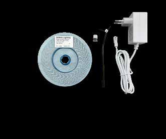
A B
C
E
D F G
Cubica Light System
Starter-Set
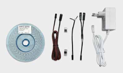
Bestehend aus:
A LED-Band (5 m)
B Verlängerungskabel
C Verbinder (LED-Band zu Kabel)
Plug & Play
D Verbinder (LED-Band zu LED-Band)
E LED-Anschlusskabel
F Y-Verteilkabel
G Netzteil (Trafo für 230 V Steckdose,
für max. 7,2 m LED-Band ausgelegt)
Zusätzlich erhältlich (nicht im Starter-Set enthalten):
Steuerungs-Set mit H Funkstecker und
I Funkschalter inkl. Batterie (CR2032)
Smart-Home-
ready
H I
Unser Verarbeitungsvideos dazu
finden Sie online unter:
www.licht-sockelleiste.de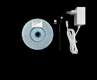
Verwendung
• Lichtsystem für die Sockelleiste „Cubica Light System“
• Starter-Set ist nur für eine Gesamtlänge von 5 m
  LED-Band vorgesehen

Hinweise zum LED-Band
• ungeschützten Leiterfilm ausschließlich
  zum Einbau in die Sockelleiste verwenden
• nicht für Feuchtraum geeignet
• LED-Band ist selbstklebend ausgestattet

Montage der Grund- und Deckprofile
Die Montageanleitung der Grund- und
Deckprofile finden Sie online unter
www.licht-sockelleiste.de, in der App
oder in unserem Downloadcenter
unter www.doellken-profiles.com.

Verfahrensweise bei der Montage des LED-Bandes

Achtung: Das Netzteil ist für maximal 7,2 m LED-Band
ausgelegt! Bevor das LED-Band zugeschnitten und
verklebt wird, sollte undegingt ein Funktionstest durch-
geführt werden!

Auf den Seiten 10-12 finden Sie eine Auflistung möglicher
Fehlerquellen bei Funktionsstörungen sowie Allgemeine
Installations- und Sicherheitshinweise.

• Kabelanschluss seitlich          • Kabelanschluss mittig
  vom Band (Steckdose                (Steckdose zwischen
  befindet sich in Raumecke)         zwei Profilen)
23 Anwendungsfälle bei der Verlegung:
    Funktionstest vor Verlegung

Vor Verlegung etwa 2 cm Schutzfolie des aufgetragenen
Fixierungsbandes vom LED-Band ablösen
und in den Verbinder ( C LED-Band zu Ka-
bel-Verbinder) setzen.               C                  G
LED-Anschluss-
kabel ( E ) mit
richtiger Polung
einführen und                             E
mit einer Zange        A
zudrücken. Netz-
teil ( G ) verbinden,
um einen Funktionstest durchzuführen.

                                    C
         A
                                               E

•3 LED-Band auf gewünschte Länge zuschneiden

  LED-Band mit Seitenschneider oder Elektrikerzange
  an der Markierung zuschneiden (alle 5 cm möglich)

• ACHTUNG: nur an der vorgesehenen Markierung
  schneiden, ansonsten ist der 5cm Abschnitt nicht
  mehr funktionstüchtig!
•4 Beginnend an der vorgesehenen Position am Profilan-
fang (Grundprofil Aussparung 1 cm) wird das LED-Band
mittels des aufgetragenen Fixierungsbandes in das
Grundprofil gleichmäßig eingeklebt – Schutzfolie des
aufgetragenen Fixierungsbandes dabei stufenweise
entfernen
•4a Direkter Anschluss von einem
einzelnen LED-Band an das Netzteil
0
A C
G
B
G
C E
D
E
F
G C
H
I
J
K
L E
M
G E
c li c k
C
A E4b
• Anschluss eines zweiten LED-Bandes
mit Hilfe des Y-Verteilkabels C
E
G F G
C C
E E
F
cl ic k
c li c k
i
N LED-Anschlusskabel können auch nach Bedarf etwas
eingekürzt werden, um die Kabel besser im Grundprofil
verstauen zu können.
• Y-Verteilkabel ( F ) und LED-Anschlusskabeln ( E ) verbinden
• beide LED-Bänder auf gewünschte Länge zuschneiden
(analog Schritt 3 )
• Funktionstest durchführen (analog Schritt 2 )
• LED-Bänder mittels des aufgetragenen Fixierungs-
bandes in das Grundprofil gleichmäßig eingekleben –
Schutzfolie des aufgetragenen Fixierungsbandes dabei
stufenweise entfernen
• Der Anschluss des zweiten LED-Bandes kann analog des
Punkt 2 der Verarbeitungsanleitung ausgeführt werden
• Y-Verteilkabel ( F ) mit Netzteilstecker ( G ) verbinden und
in den unteren Teil des Grundprofils platzieren
• Erneuter Funktionstest bevor Deckprofil montiert wird
1
ACHTUNG: Das Netzteil ist für max. 7,2 m LED-Band ausgelegt!4c
• Anschluss eines weiteren LED-Bandes
mit Hilfe des Y-Verteilkabels und C
2,5 m Verlängerungskabels
ACHTUNG: Das Netzteil ist für
B
max. 7,2 m LED-Band ausgelegt! E
F G
G
Verlängerungs-
kabel zur Erwei-
terung bis 2,50 m
C C
E B E
F
cl ic k
cl ic k
c li c k
cl ic k
i 0 kabel
Für die Verlängerung des Y-Verteil-
wird das Verlängerungskabel
(z.B. zum Verlegen des Kabels hinter
einem Schrank) benötigt.
• Y-Verteilkabel ( F ) direkt mit dem LED-Anschlusskabel
( E ) verbinden und erstes LED-Band anschließen
• an die zweite Ader des Y-Verteilkabel ( F ) das Ver-
längerungskabel( B ) einsetzen und zweites LED-Band
mit einem weiteren LED-Anschlusskabel ( E ) verbinden
• LED-Bänder auf gewünschte Länge zuschneiden
(analog Schritt 3 )
• Funktionstest durchführen (analog Schritt 2 )
• LED-Bänder mittels des aufgetragenen Fixierungs-
bandes in das Grundprofil gleichmäßig eingekleben –
Schutzfolie des aufgetragenen Fixierungsbandes
dabei stufenweise entfernen
• Y-Verteilkabel ( F ) mit Netzteilstecker ( G ) verbinden
und Kabel im unteren Teil des Grundprofils platzieren
• Erneuter Funktionstest bevor Deckprofil montiert wird
15 Anschluss LED-Bänder über Ecken • Es ist unbedingt darauf zu achten, dass das LED-Band gleichmäßig und locker im Bereich von Außen- und Innenecken verlegt wird. Es darf nicht geknickt und gezogen werden (siehe Biegeradius „Allgemeine Installationshinweise”) 6 Verwendung von Verbindern Verbinder [LED-Band zu Kabel] ( C ) • zur Verbindung von LED-Bändern und LED-Anschlusskabel Verbinder [LED-Band zu LED-Band] ( D ) • können zur Fortführung von LED-Band- Abschnitten verwendet werden, um eine nahtlose Verbindung herzustellen Sonderfall „Cubica LS Light up (Licht oben)”: • zur Verbindung der LED-Band-Abschnitte bei Verle- gung von Außenecken der Cubica LS Light up (Licht oben), wird ein zusätzliches Kabelset (Art.Nr. 5905798) benötigt. Dieses muss bei Bedarf zusätzlich gekauft werden und ist nicht im Starter-Set enthalten. Haben Sie Fragen zum Produkt? Dann rufen Sie uns gern an unter: +49 3643/ 4170-711 oder schreiben Sie uns eine E-Mail: info@doellken-profiles.com
7 Montage des Deckprofils

• Hinweise zur Montage des
  Deckprofils finden Sie in der
  Verarbeitungsanleitung
  „Cubica Light System (Grund-
  und Deckprofil)” bzw. online        Einfach mit dem
  unter www.licht-sockelleiste.de   Smartphone scannen

                                       ––

                                       ++
Sollte das LED-Band vor bzw. nach der
Verlegung nicht leuchten, prüfen Sie bitte, ...
... ob das LED Band Kontakt mit sich selbst (also in sich
verdreht) oder einer anderen metallischen (leitenden)
Oberfläche hat (Kurzschluss)
... ob das Netzteil eingesteckt ist (in eine funktionierende
Steckdose, bei Steckdosenleisten mit Schalter: selbigen
prüfen, ob er angeschaltet ist) und das Netzteil mit dem
Y-Verteilkabel (oder LED-Anschlusskabel) verbunden ist
... ob der Stecker von dem LED-Anschlusskabel mit dem
Verbinder (PTF) richtig mit dem LED Band verbunden ist
Dabei prüfen ob, ...
• die Seite mit dem schwarzen Draht auf dem Kontakt
liegt, der auf dem Band mit (-) „Minus“ gekennzeichnet
ist. Dementsprechend roter Draht an Plus (+24V).
• der PTF-Stecker (Verbinder) richtig herum gedreht
ist. Das Band kann oben und unten angeschlossen
werden, um die Polung drehen zu können (siehe 1.
Punkt). Der PTF-Stecker hat Kontakte auf der „dickeren“
Seite, d.h. wenn der Stecker gedreht werden muss,
müssen u. U. die Kontakte auf der Unterseite des LED
Bandes benutzt werden. Dort muss dann aber vorher
das Doppelklebeband an der Stelle entfernt werden.
• der Stecker beim Anschließen oder Verkleben heraus-
gerutscht ist. Wenn man den Stecker zudrückt, drückt
sich ein Dorn durch das Band, um dies zu verhindern.
Sie haben Fragen oder
Probleme bei der Montage
bzw. Installation?
Schauen Sie doch mal in
unser Verarbeitungsvideo
oder rufen Sie uns an unter:
+49 3643/ 4170-711.Allgemeine Installationshinweise
Bitte beachten Sie alle nachfolgenden Installations-
hinweise. Ein Nichtbeachten führt zum Erlöschen der
Garantieansprüche.
• Biegeradius horizontal (Band flach) >= 200 mm
• Biegeradius vertikal (Band aufrecht) >= 50 mm
• Bänder nicht knicken
• Bänder während der Installation nicht verdrillen
• das aufgerollte LED-Modul nicht werfen, sondern auf
einer horizontalen Fläche gleichmäßig entrollen
• Krafteinwirkung, Zugbelastung oder sonstige mechanis-
che Einflüsse im Bereich des Anschlusses ist während
der Installation zu vermeiden und durch entsprechende
Sicherung der Kabel im installierten Zustand komplett
auszuschließen
• Während der Installation mechanische Einflüsse auf
jeden Bereich des Produkts vermeiden
• Bei der Installation von Längen über 1,5 m ist erhöhte
Sorgfalt walten zu lassen, sodass die Leiterfilme bzw.
elektronischen Komponenten nicht beschädigt werden
• Aufgrund der eingesetzten Materialien sind Längenaus-
dehnungen von bis zu +/- 2 mm je Meter pro 10 Kelvin
Temperaturdifferenz möglich
Elektrische Inbetriebnahme
• Hinsichtlich der Verdrahtung der LED-Module mit Control-
lern und Vorschaltgeräten ist das jeweilige Datenblatt
des Produkts sowie die Vorgaben der Hersteller der
jeweiligen Elektronik bindend.Sicherheitshinweise
• Die Installation der Produkte muss unter Beachtung der
vorliegenden Anleitungen, technischen Datenblätter
sowie Einhaltung aller nationalen gesetzlichen Vorgaben
und Normen erfolgen
• Döllken Profiles übernimmt keinerlei Haftung für durch
unsachgemäße Handhabung entstandene Schäden bei
Montage oder generellem Einsatz der Produkte.
• Selbst durchgeführte Änderungen an den Produkten
führen zum Erlöschen der gültigen Zertifikate und Garan-
tievereinbarungen
• Die Verbindung zur Netzspannung muss zwingend vor
jeder Installation oder Wartungsarbeit an den Produkten
unterbrochen werden
• Es ist darauf zu achten, dass die Verbindung von
Anschlusskabel zu Spannungsversorgung/Steuerungs-
einheit entsprechend der benötigten Schutzart des
Installationsortes ausgeführt ist
• Die genutzte Elektronik muss zu den entsprechenden,
leistungsbezogenen Daten der individuellen Modullängen
genügen
• Die LED-Module sollten nur mit SELV–Betriebsgeräten
betrieben werden, die das CE-Zeichen tragen und die
Konformität nach mindestens der Norm EN-61347-2-13
bestätigen. Betriebsgeräte sollten folgende Schutz-
maßnahmen aufweisen: Kurzschlussschutz, Überlast-
schutz und Übertemperaturschutz. Achten Sie dabei
auf das Prüfzeichen eines unabhängigen berechtigten
Prüfinstitutes
• Nur die elektrische Parallelschaltung ermöglicht einen
sicheren Betriebszustand. Von der elektrischen Reihen-
schaltung der LED-Module wird ausdrücklich abgeraten.
Unsymmetrische Spannungsabfälle können zu einer
starken Überlastung und Zerstörung einzelner Module
führen
• Vermeiden Sie elektrostatische Entladungen (ESD) bei
der Installation
Batterien und Akkus
dürfen nicht in den
RoHS
Hausmüll!Installation
instruction
Cubica Light System
ENG
Starter-Set
For the installation you need:
Döllken Screwdriver Side cutters or Pliers
skirting scissors electrician‘s pliers
5905392A B
C
E
D F G
Cubica Light System
Starter Set
Consisting of:
A LED tape (5 m)
B Extension cable
C Connector (LED tape to cable)
Plug & Play
D Connector (LED tape to LED tape)
E LED connection cable
F Y-distribution cable
G Power supply (transformer for 230 V socket,
designed for max. 7.2 m LED-tape)
Additionally available
(not included in the starter set):
Control set with H radio plug and
I radio switch incl. battery (CR2032) Smart-Home-
ready
H I
Our processing videos for this
can be found online:
www.cubica-light.deUse • Light system for the skirting board “Cubica Light System” • Starter set is only intended for a total length of 5 metre LED tape Notes about the LED tape • use unprotected conductor film exclusively for installation in the skirting board • not suitable for damp locations • LED tape is equipped with self-adhesive Mounting of the base and cover profiles The mounting instructions for the base and cover profiles can be found online www.licht-sockelleiste.de, in the app or in our download center at www.doellken-profiles.com. Procedure for mounting the LED strip Attention: The power supply is designed for a maximum of 7.2 m LED tape! Before the LED tape is cut and glued, a function test should be carried out! On pages 10-12 you will find a list of possible sources of error in the event of malfunctions as well as general instal- lation and safety instructions. • Cable connection on the • Cable connection side of the belt (socket is centrally (socket located in the corner of the between two profiles) room)
2 Cases of application during installation:
  Function test before laying

Before laying, peel off about 2 cm of protective film of the
applied fixing tape from the LED tape and place it
in the connector ( C LED tape to cable
connector).                             C                    G
Insert LED connec-
tion cable ( E )
with correct
polarity and                                  E
press shut with          A
pliers. Connect the
power supply unit ( G )
to perform a function test.

                                       C
          A
                                                   E

3• Cut LED tape to desired length

• cut the LED tape at the marking (every 5 cm possible)
  with side cutters or electrician’s pliers

• ATTENTION: cut only at the intended marking cut,
  otherwise the 5cm section is no longer functional!
•4 Starting at the intended position at the beginning of
the profile (base profile recess 1 cm), the LED tape is
glued evenly into the base profile using the applied
fixing tape - remove the protective film of the applied
fixing tape step by step.
•4a Direct connection of a single LED strip to the power
supply
0
A
B C
G
C
G
D E
E
F
G
H C
I
J
K
L
M E
G E
c li c k
C
A E4b
• Connection of a second LED strip
using the Y-distribution cable C
E
G F G
C C
E E
F
cl ic k
c li c k
i 0 LED connection cables can also be shortened slightly
as needed to better stow the cables in the base profile.
• connect Y-distribution cable ( F ) and LED connecting
cables ( E )
• Cut both LED strips to the desired length
(analogous to step 3 )
• Perform function test (analog step 2 )
• Glue the LED strips evenly into the base profile using the
applied fixing tape - remove the protective film of the
applied fixing tape step by step
• The second LED strip can be connected in the same way
as in point 2 of the processing instructions.
• connect Y-distribution cable ( F ) with power supply plug
( G ) and place it in the lower part of the base profile
• Renewed function test before cover profile is mounted
1
ATTENTION:
The power supply is designed for max. 7.2 m LED tape!4c
• Connection of another LED strip
using the Y-distribution cable and C
2.5 meter extension cable
The power supply is designed for
B
a maximum of 7.2 m LED tape! E
F G
G
Extension cable
for extension up to
2.50 meter
C C
E B E
F
cl ic k
cl ic k
c li c k
cl ic k
i 0 bution
For the extension of the Y-distri-
cable, the extension cable
(e.g. for laying the cable behind a
cabinet) is required.
• connect Y-distribution cable ( F ) directly to LED
connection cable ( E ) and connect first LED tape
• to the second wire of the Y-distribution cable ( F )
insert the extension-cable( B ) and connect a second
LED ribbon with another LED connection cable ( E )
• Cut LED strips to desired length (analog step 3 )
• Perform function test (analog stept 2 )
• Glue the LED tape evenly into the base profile using the
applied fixing tape - remove the protective film of the
applied fixing tape step by step.
• connect Y-distribution cable ( F ) with power supply
plug ( G ) and place cables in the lower part of the
base profile
• Before the cover profile is mounted, repeat the function
test.
15 Connection LED strips via corners • It is essential to ensure that the LED tape is laid evenly and loosely in the area of external and internal corners. It must not be kinked and pulled (see bending radius “General installation instructions”). 6 Use of connectors Connector [LED tape to cable] ( C ) • for connecting LED strips and LED connection cables Connector [LED tape to LED tape] ( D ) • Can be used to continue LED tape sections to create a seamless connection Special case „Cubica LS Light up”: • when installing outside corners of the Cubica LS Light up, an additional cable set (Art.No. 5905798) to connect the LED strip sections is needed. This must be purchased additionally if required and it is not included in the starter set. Do you have any questions about the product? Then please feel free to call us at: +49 3643/ 4170-711 or send us an e-mail: info@doellken-profiles.com
7 Mounting of the cover profile

• Instructions for mounting the
  cover profile can be found
  in the processing instructions
  “Cubica Light System (base
   and cover profile)” or online    Just scan with
  www.cubica-light.de/en           your smartphone

                                     ––

                                     ++
If the LED strip is not lit before or after the ins-
tallation, please check ...
... whether the LED strip has contact with itself (i.e.
whether it is twisted) or with another metallic (conductive)
surface (short circuit)
... whether the power supply unit is plugged in (into a func-
tioning socket; in the case of socket strips with a switch:
check whether the switch is switched on) and check
whether the power supply unit is connected with
the Y-distribution cable (or LED connection cable)
... whether the plug of the LED connecting cables with the
Connector (PTF) is properly connected with the LED strip
Check whether ...
• the side with the black wire is applied to the contact
that is labelled with (-) “minus” on the strip. Corre-
spondingly red wire on plus (+24V).
• the Connector/PTF plug is turned to the right side.
The strip can be connected at the top and bottom, in
order to be able to switch the polarity (see item 1).
The Connector/PTF plug is provided with contacts on
the “thicker” side, i.e. if the plug has to be turned, you
might have to use the contacts on the bottom side of
the LED strip. However, then you’ll have to remove the
double-sided tape there first.
• the plug has slipped out during the glueing process
or while the connection was made. If you squeeze the
plug, a mandrel will push through the strip in order to
prevent this.
Do you have questions or
problems with the installation?
Have a look at our processing
video or call us at:
+49 3643/ 4170-711.General installation instructions Please note the following installation instructions. Non-compliance results in expiry of guarantee claims. • horizontal bending radius should not be less than >= 200 mm • vertical bending radius should not be less than >= 50 mm • Do not bend the modules at sharp angles • Do not twist the strips during the installation • Do not throw the roll but unwind evenly, but roll out evenly on a horizontal surface • Avoid bringing force to bear on or tensioning the connec- tions of the strips during installation and secure the wiring to fully exclude this after installation • Avoid bringing mechanical forces to bear on any part of the product during installation • Exercise particular care when installing lengths in excess of 1.5 m to prevent damage to the conducting foil or electronic components • The materials used will allow changes in length of up to ± 2 mm/m per 10 K temperature difference Electrical commissioning • The specific product data sheet and the specifications by the manufacturers of electronic equipment are binding in terms of the wiring of LED modules to controllers and upstream devices
Safety instructions

• Installation of the products shall be carried out exclu-
  sively by suitably qualified electrical technicians and
  with due regard to these instructions, the technical data
  sheets and compliant with all national standards and
  statutory requirements
• Döllken Profiles accepts no liability for damage caused
  by improper handling during installation or general
  deployment of the product
• Any unauthorised changes to the products will render rele-
  vant certificates and warranty agreements null and void
• Be sure to isolate from mains voltage before installation
  or servicing
• Ensure that the connection of the connecting cable to
  mains supply/controller complies with the wiring regula-
  tions at your location
• The electronic supply must be in agreement with the given
  power requirements for the specific module lengths. For
  individual specifications, please refer to the technical
  datasheets for the specific product version
• The LED modules should only be operated with SELV
  controllers carrying the CE mark and complying at least
  with EN-61347-2-13. The controllers should include the
  following protection: Short-circuit, overload and over-
  temperature protection. Ensure that the test mark is that
  of an independent authorised test institution
• Safe operation is ensured only by electrical connection
  in parallel. Series connection of the LED modules is
  expressly not recommended
• Non-symmetric voltage drops may result in serious over-
  loading and the destruction of individual modules
• Prevent electrostatic discharges (ESD) during installation
   Batteries and accumulators
   must not be disposed of in   RoHS
   the household waste.

Mit Erscheinen dieser Version werden alle vorherigen Versionen ungültig.
Publication of this version shall render all prior versions invalid.
Letztes Update: 19.04.2021 / Last update: 19.04.2021

Döllken Profiles GmbH               T: +49 3643 4170 711
Industriestraße 1                   F: +49 3643 4170 330
59199 Bönen                         info@doellken-profiles.com
Follow us on                        www.doellken-profiles.com
Sie können auch lesen