773E Photocells manual - Photocells - De Rooij Garagedeuren
←
→
Transkription von Seiteninhalten
Wenn Ihr Browser die Seite nicht korrekt rendert, bitte, lesen Sie den Inhalt der Seite unten
manual
                                           Photocells

773E Photocells

Photocells
© All rights reserved. FlexiForce®, 2014

                             FF-MANUEL SuperClick       www.flexiforce.com
de LICHTSCHRANKE MODELL 773E
en PHOTOCELLS MODEL 773E
fr PHOTOCELLULES MODÈLE 773E
nl FOTOCELBEVEILIGING MODEL 773E
Chamberlain GmbH
Alfred-Nobel-Strasse 4
D-66793 Saarwellingen
Germany
www.liftmaster.eu
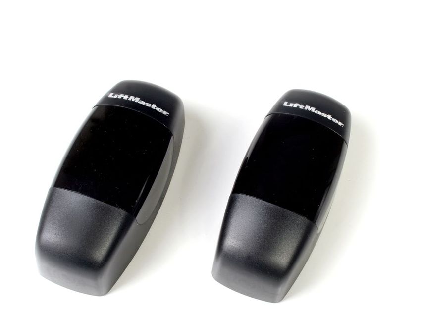
info@liftmaster.eu1 FUNKTION Die 773E ist eine Lichtschranke, bestehend aus einem Sender (TX) und einem Empfänger (RX). Sie verfügt über einen potentialfreien NC Kontakt (Standard). Bei Bedarf kann dieser auf NO Kontakt modifiziert werden (optional, siehe Punkt 4). Der Sender (TX) sendet einen Infrarotstrahl zum Empfänger (RX). Eine Unterbrechung des Infrarotstrahls wird erfasst und an die Steuerung übertragen. Eine einwandfrei funktionierende Lichtschranke dient lediglich der Erkennung von Personen oder Objekten im Torbereich und gewährleistet keine absolute Sicherheit für andere, durch die Torbewegung entstehende, Gefahren. Treffen Sie ggf. weitere Schutzmassnahmen. 2 MONTAGE Zum Schutz von Kleinkindern sollte die Lichtschranke nicht höher als 200 mm - 250 mm über dem Garagenboden installiert werden. Achtung: - Installationen an Hanglagen oder schrägen Einfahrten erfordern besonders präzises Arbeiten. - Kabellängen von mehr als 10 m vermeiden. - Tiefstehende Sonne oder unterdimensionierte Leitungen können die Reichweite stark reduzieren. - Werden 2 Lichtschranken in geringem Abstand neben/übereinander montiert (z.B. bei Schiebetoren), dürfen die Empfänger bzw. Sender nicht auf der glei- chen Seite der Einfahrt montiert werden, da sonst ein Sender (TX) beide Empfängerlinsen beeinflussen kann. Vor der Montage muss die Stromzufuhr abgeschaltet werden. 1. Mit einem geeigneten Schraubendreher die Rastnase eindrücken und das Gehäuse öffen (Abb.1). Dieser Schnappmechanismus ermöglicht eine schnelle Montage. Das Gehäuse während der Installation offen lassen, damit die Diagnose der LED gesehen werden kann. 2. Sender und Empfänger entsprechend montieren und ausrichten. Mindestens je 2 Schrauben zur Befestigung des Senders und Empfängers nutzen und dabei beachten, dass die Kabelführung ordnungsgemäss ausgeführt wird (Abb. 5). Die Sensoren so ausrichten, dass die Linsen parallel zum geschlossenen Tor genau aufeinander zeigen. Die 773E verfügt innen über eine schwenkbare Linsenhalterung, welche eine optionale Justierung (Abb. 3b) ermöglicht. Nach der Justierung die beiden Schrauben (8) anziehen (Abb. 6). 3. Die Anschlussleitung muss entsprechend der lokalen Bau- und Elektroinstalla- tionsvorschriften verlegt werden. Hochspannung und Niederspannung dürfen nicht zusammen in einer Leitung/Kabel geführt werden; dies führt zur Fehlfunktion. 4. Die Kabel (min. 2 x 0,5 mm²) je nach Steuerung mit den Klemmen verbinden.
5. Nach erfolgtem Anschluss der Lichtschranken den Antrieb in Betrieb nehmen.
Hinweise: Grüne LED des Senders (6) leuchtet auf, wenn Spannung anliegt.
          Die rote LED des Empfängers (7) leuchtet, wenn Sender und
          Empfänger nicht ordnungsgemäss ausgerichtet sind oder ein Hindernis
          den Lichtstrahl unterbricht (Abb 2a).
6. Das Gehäuse der Lichtschranke schliessen.

3    INBETRIEBNAHME UND TEST DER LICHTSCHRANKE
• Mit der Fernbedienung oder einem Taster das Tor öffnen.
• Ein Hindernis zwischen Sender und Empfänger platzieren, um den Infrarotstrahl
  zu unterbrechen.

4    MODIFIKATION
Der Kontakt des Empfängerteils ist gewöhnlich geschlossen (NC Kontakt), wenn
der Empfänger gespeist und mit dem Sender gefluchtet ist. Sollte ein gewöhnlich
geöffneter Kontakt ( NO Kontakt) erforderlich sein, nehmen Sie die Elektronik von
der Plastikhalterung, schneiden die Bahn A durch und stellen (löten) die
Verbindung B her wie in Abbildung 7 gezeigt.
Wahl der Spannungsversorgung (12 V / 24 V) mittels Jumper siehe Abbildung 2a.

5    FEHLERSUCHE
Die LED Anzeige bei Sender und/oder Empfänger leuchtet
nach der Installation nicht. Überprüfen Sie folgende Punkte:
• Spannungsversorgung der Anlage
• Eventueller Kurzschluss
• Falscher Leitungsanschluss zwischen Sensor und Steuerung
• Unterbrochene bzw. fehlende Leitung
• Polarität der Kabel vertauscht

6    TECHNISCHE DATEN
Schutzklasse:                        IP44
Temperaturbereich:                   - 10°C + 70°C
Reichweite:                          25m
Versorgung:                          V AC/V DC 12/24+/-10%
Verbrauch RX (24 V AC) :             40 mA
Verbrauch TX (24 V AC) :             50 mA
Höchststrom Relaiskontakte:          1A
Höchstspannung Relaiskontakte:       30 V DC

Zubehör (Abb.8)
1 FUNCTION The 773E is a photoelectric barrier, comprising a transmitter (TX) and a receiver (RX). It has a potential-free NC contact (standard). If required, this can be modified to a NO contact (optional, see point 4). An interruption of the infrared beam is detected and transmitted to the controller. A perfectly functioning photocell serves only to identify persons or objects in the door area and does not ensure absolute safety from other hazards arising from the door movement. If necessary, take additional protective measures. 2 ASSEMBLY For the protection of young children, the photocell should not be installed higher than 200 mm - 250 mm above the garage floor. Attention: - Installations on slopes or slanted driveways require very precise work. - Avoid cable lengths of more than 10 m. - Low angle sunshine or under-sized cables can greatly reduce the range. - If 2 photocells are installed close to each other with little distance between them (e.g. for sliding doors), the receiver and transmitter should not be mounted on the same side of the entrance, or else one transmitter (TX) can influence both receiver lenses. Before installing the photocell, the power supply must be shut down. 1. Press in the latch with a suitable screwdriver and open the housing (Fig. 1). This snap mechanism enables quick installation. Keep the housing open during the installation so that the diagnosis of the LED can be seen. 2. Mount and align transmitter and receiver accordingly. Use at least 2 screws for attaching the transmitter and receiver, and ensure that the cable routing is exe- cuted properly (Fig. 6). Align the sensors in such a way that the lenses precise- ly face each other parallel to the door. There is a bracket for the lens inside the 773E, which enables an optional alignment (Fig. 3b). After alignment, tighten the two screws (8) (Fig. 7). 3. The connection cable must be laid in accordance with local building and electri- cal regulations. High and low voltage lines are not to be laid together in a single cable; it leads to malfunction. 4. Connect the cable (min. 2 x 0.5 mm2) to the terminals according to the controller.
5. After connecting the photocells, operate the drive.
Notes: The transmitters green LED (6) lights up if voltage is impressed.
         The receivers red LED (7) glows if TX and RX aren’t properly aligned or
         the if the beam is interrupted by an obstruction (Fig 2a).
6. Close the housing of the photocell.

3    INITIAL OPERATION AND TESTING OF PHOTOCELLS
• Open the door with the remote control or a switch.
• Place an obstacle between the transmitter and receiver to interrupt the infrared
  beam.

4    MODIFICATION
The photocell's receiver part contact is normally closed (NC contact), whenever
the receiver is saved and aligned with the transmitter. Should a normally opened
(NO contact) be required, remove the electronics module from the plastic mount-
ing, cut through track A and execute the weld B, as shown in figure 7.
Select suitable voltage (12 V / 24 V) with the jumper as shown in figure 2a.

5    TROUBLESHOOTING
The LED indicator on transmitter and/or receiver does not light up after installa-
tion. Check the following points:
• Power supply of the system
• Potential short-circuit
• Incorrect cable connection between sensor and controller
• Broken or missing cable
• Polarity of the cables are interchanged

6    TECHNICAL DATA
Protection class:                     IP44
Temperature range:                    - 10°C + 70°C
Range:                                25 m
Power supply:                         V AC/V DC 12/24+/-10%
Consumption RX (24 V AC):             40 mA
Consumption TX (24 V AC):             50 mA
Relay contacts max. current:          1A
Relay contacts max. voltage:          30 V DC

Accessories (Fig.8)
1 FONCTION La 773E est une barrière lumineuse composée d'un émetteur (TX) et d'un récep- teur (RX). Elle dispose d'un contact sans potentiel NF (standard). Si nécessaire, ce contact peut être remplacé par un contact NO (en option, voir point 4). L’interruption du rayon infrarouge est détectée et transmis à la commande. Une photocellule en parfait état de fonctionnement sert uniquement à la détection des personnes ou objets dans la zone de porte et n’assure pas une sécurité absolue contre les autres risques générés par le mouvement de la porte. Le cas échéant, prenez des mesures complémentaires. 2 MONTAGE Pour la protection des enfants en bas âge, la photocellule doit être installée à une hauteur maximale de 200 à 250 mm au dessus du sol du garage. Attention : - Des installations en pente ou sur des entrées inclinées exigent un montage particulièrement précis. - Eviter les longueurs de câbles supérieures à 10 m. - Un soleil rasant ou des câbles sous-dimensionnés peuvent considérablement réduire la portée. - Si deux photocellules sont montées très proches l’une de l’autre (par ex. pour des portes coulissantes), les récepteurs et les capteurs ne doivent pas être montés sur le même côté de l'entrée, puisque dans ce cas, un émetteur (TX) pourrait influencer les deux lentilles de récepteur. Avant le montage de la photocellule, vous devez interrompre l’alimentation électrique. 1. Au moyen d’un tournevis approprié, enfoncez le tenon d’enclenchement et ouvrez le boîtier (Fig. 1). Ce mécanisme enclencheur permet un montage rapide. Laissez le boîtier ouvert pendant l’installation, afin que vous puissiez observer les DEL de diagnostic. 2. Montez et alignez l’émetteur et le récepteur. Utilisez au moins 2 vis pour le montage de l’émetteur et de récepteur, et veillez à ce que les câbles soient correctement posés (Fig. 6). Alignez les capteurs de sorte que les lentilles soient orientées avec précision les unes vers les autres et parallèlement à la porte fermée. La 773E est dotée à l’intérieur d’un support de lentille pivotable qui permet un ajustage optimal (Fig. 3b). Après l’ajustage, serrez les deux vis (8) (Fig. 7). 3. Le câble de branchement doit être posé conformément aux réglementations locales en matière de constructions et d’installations électriques. La haute tension et la basse tension ne doivent pas être posées ensemble dans un câble, puisque cela génère des dysfonctionnements. 4. Raccordez les câbles (min. 2 x 0,5 mm²) aux bornes en fonction de la commande.
5. Après le branchement des photocellules, mettez l’entraînement en service.
Notices: La led verte de l'emetteur (6) s'allume, si le système est sous tension.
         La led rouge du récepteur (7) s'allume, si l'émetteur et le récepteur n'ont
         pas été installés correctement ou si un obstacle interrompt le faisceau
         de lumière (Fig.2a).
6. Fermez le boîtier de la photocellule.

3    MISE EN SERVICE ET ESSAIS DE LA PHOTOCELLULES
- Ouvrez la porte avec la télécommande ou un bouton.
- Placez un obstacle entre l’émetteur et le récepteur pour interrompre le rayon
  infrarouge.

4    MODIFICATION
Le contact de la partie récepteur de la cellule photo est normalement fermé (con-
tact NF) lorsque le récepteur est alimenté et en ligne avec l'émetteur. Si un con-
tact normalement ouvert est requis (contact NO), retirer l'élément électronique du
support en plastique, découper la membrane A et exécuter la soudure B comme
montré sur l'illustration 7.
Choix de l'alimentation ( 12V /24V) par le biais du cavalier. Voir aussi figure 2a.

5    RECHERCHE DES DEFAILLANCES
Le témoin à DEL de l’émetteur et/ou du récepteur ne s’allume pas après l’installa-
tion. Contrôlez les points suivants :
- Alimentation électrique de l’installation
- Eventuel court-circuit
- Branchement erroné des câbles entre le capteur et la commande
- Câble interrompu ou absent
- Inversion de la polarité des câbles

6    CARACTERISTIQUES TECHNIQUES
Classe de protection:                 IP44
Plage de température:                 - 10 °C + 70 °C
Portée:                               25 m
Alimentation:                         V AC/V DC 12/24+/-10%
Consommation RX (24 V AC):            40 mA
Consommation TX (24 V AC):            50 mA
Courant max. contacts relais:         1A
Tension max. contacts relais :        30 V DC

Accessoires (Fig.8)
1 FUNCTIE De 773E is een foto-elektrische beveiliging, bestaande uit een zender (TX) en een ontvanger (RX). Ze beschikt over een potentiaalvrij NC-contact (stan- daard). Indien nodig, kan dit worden veranderd in een NO-contact (optioneel, zie punt 4). Een onderbreking van de infraroodstraal wordt geregistreerd en aan de sturing gemeld. Een onberispelijk functionerende foto-elektrische beveiliging dient enkel om personen of voorwerpen binnen het bereik van de poort te detecteren en garandeert geen absolute zekerheid voor andere gevaren die ontstaan door de beweging van de poort. Neem evt. bijkomende bescher- mingsmaatregelen. 2 MONTAGE Om kleine kinderen te beschermen, mag de foto-elektrische beveiliging niet hoger dan 200 mm - 250 mm boven de garagevloer worden geïnstalleerd. Opgelet: - Installaties op een helling of schuine opritten vergen uiterst nauwkeurig werk. - Kabellengtes van meer dan 10 m vermijden. - Een laagstaande zon of ondergedimensioneerde leidingen kunnen het bereik sterk verminderen. - Worden twee foto-elektrische beveiligingen op geringe afstand naast/onder elkaar gemonteerd (bijv. bij schuifpoorten), dan mogen de ontvanger en zender niet aan dezelfde kant van de inrit worden gemonteerd, aangezien een zender (TX) anders beide ontvangerlenzen kan beïnvloeden. Voor de montage van de foto-elektrische beveiliging moet de stroomtoevoer worden uitgeschakeld. 1. Met een geschikte schroevendraaier de aanslagneus indrukken en de behuiz- ing openen (afb. 1). Dankzij dit klikmechanisme is een snelle montage mogelijk. De behuizing open laten tijdens de installatie, opdat de diagnose van de LED zichtbaar is. 2. Zender en ontvanger monteren en uitrichten. Telkens minstens twee schroeven gebruiken om de zender en ontvanger te bevestigen en let er daarbij op dat de kabelgeleiding correct wordt uitgevoerd (afb. 6). De sensoren zo uitrichten dat de lenzen parallel tegenover de gesloten poort precies naar elkaar wijzen. De 773E beschikt inwendig over een zwenkbare lensbevestiging, waarmee een optionele bijstelling (afb. 3b) mogelijk is. Na de bijstelling beide schroeven (8) vastdraaien (afb. 7). 3. De aansluitleiding moet volgens de plaatselijke bouw- en elektrische instal- latievoorschriften worden gelegd. Hoog- en laagspanning mogen niet samen in één leiding/kabel worden geleid; dit leidt tot storingen. 4. De kabels (min. 2x 0,5 mm²) naargelang de sturing met de klemmen verbinden.
5. Na het aansluiting van de foto-elektrische beveiligingen kunt u de aandrijving in
   gebruik nemen.
Opmerkingen: Groene LED van de zender (6) is aanals deze spanning krijgt.
               Rode LED van de ontvanger (7) is aan als zender en ontvanger
               niet goed uitgelijnd zijn of als een obstakel de lichtstraal onder
               breekt (afb.2a).
6. De behuizing van de foto-elektrische beveiliging sluiten.

3    INGEBRUIKNEMING EN TEST VAN DE FOTO-ELEK-
     TRISCHE BEVEILIGING
• Met de afstandsbediening of een toets de poort openen.
• Een hindernis tussen zender en ontvanger plaatsen om de infraroodstraal te
  onderbreken.

4    MODIFICATIE
Het contact van het ontvangergedeelte van de fotocel is gewoonlijk gesloten (NC-
contact), wanneer de ontvanger gevoed is en met de zender op één lijn staat.
Indien een gewoon geopend contact (NO-contact) nodig is, neemt u de elektroni-
ca van de plastic houder, snijdt u baan A door en voert u las B uit, zoals geïllus-
treerd in afbeelding 7.
Kies de spanningsverzorging (12 V / 24 V)door plaatsing van de jumper.
Zie afbeelding 2a.

5    FOUTOPSPORING
De LED Anzeige (weergave) bij zender en/of ontvanger licht niet op na de instal-
latie. Controleer de volgende punten:
• Stroomvoorziening van de installatie
• Eventuele kortsluiting
• Verkeerde leiding aangesloten tussen sensor en sturing
• Onderbroken of ontbrekende leiding
• Polariteit van de kabels verwisseld

6    TECHNISCHE GEGEVENS

Veiligheidsklasse:                     IP44
Temperatuurbereik:                    - 10°C + 70°C
Bereik:                               25m
Stroomvoorziening:                    V AC/V DC 12/24+/-10%
Verbruik RX (24 V AC) :               40 mA
Verbruik TX (24 V AC) :               50 mA
Max. stroom contacten relais:         1A
Max. spanning contacten relais:       30 V DC

Accessoires (afb.8)
1
2 2a3a Sensormodul Sensormodul Module détecteur Module détecteur Sensor module Sensor module Sensormodule Sensormodule
3b

                  4
    200 - 250mm

6
                  5
7
A
NC
13800
B
NO
138008 optional
77XVP (2x)
77XVP (2x)
48
132
116
122
132
132
110
150
116
77XAP
77XAP (2x)
(2x)77C02 (1x)
77C01 (2x)
132EC - Producer’s - Declaration of Conformity
We Chamberlain GmbH
Alfred-Nobel-Strasse 4 D66793 Saarwellingen
declare, that the following machinery complies with all the essential health and safety
requirements of the Directive
Description of machinery: Photocell Type of machinery: 773E
EU Directives: EC Directive for low voltage 2006/95/EC
EC Directive electromagnetic compatibility
2004/108/EC with amendments
Applicable harmonized standards: EN 55011, EN 55014, EN 60555-2/-3
Christoph Marny
Manager, Regulatory Affairs
Chamberlain GmbH
D-66793 Saarwellingen
Germany
January 2012
W1-704920 © 2012, All rights reserved 773ESie können auch lesen