COMFOAIR 70 / COMFOSPOT 50 - SENSORIK - SENSOR SYSTEM - CAPTEURS - SENSORI - SENSORSYSTEEM - CZUJNIKI - ZEHNDER
←
→
Transkription von Seiteninhalten
Wenn Ihr Browser die Seite nicht korrekt rendert, bitte, lesen Sie den Inhalt der Seite unten
Decorative radiators   Comfortable indoor ventilation   Heating and cooling ceiling systems   Clean air solutions

 ComfoAir 70 / ComfoSpot 50
 Sensorik - Sensor system - Capteurs - Sensori -
 Sensorsysteem - Czujniki

  Montagehinweise - Installation notes - Instructions de montage - Indicazioni per
  il montaggio - Montageaanwijzingen - Wskazówki dotyczące montażu
Alle Rechte vorbehalten.
Die Zusammenstellung dieser Bedienungsanleitung erfolgte mit größter Sorgfalt. Dennoch
haftet der Herausgeber nicht für Schäden aufgrund von fehlenden oder nicht korrekten
Angaben in dieser Bedienungsanleitung. Bei Meinungsverschiedenheiten ist der deutsche
Originaltext letztendlich verbindlich.

All rights reserved.
This manual has been compiled with the utmost care. However, the publisher cannot be
held liable for any damage caused as a result of missing or incorrect information in this
manual. In case of disputes the German version of these instructions will be binding.

Tous droits reserves.
Ce manuel a ete compose avec le plus grand soin. L‘editeur ne peut neanmoins pas
etre tenu responsable de dommages decoulant d‘informations manquantes ou erronees
dans ce manuel. En cas de différend, seule la version allemand de ce mode d’emploi est
contraignante.

Tutti i diritti riservati.
La presente documentazione e stata redatta con la massima attenzione. L‘editore non
puo comunque essere ritenuto responsabile di eventuali danni derivanti dalla mancanza
o dall‘inesattezza delle informazioni qui fornite. In caso di disaccordo, fa fede l‘originale
in lingua tedesca.

Alle rechten voorbehouden.
Bij de samenstelling van deze handleiding is uiterste zorg betracht, de uitgever kan echter
niet verantwoordelijk worden gehouden voor enige schade ontstaan door het ontbreken of
onjuist vermelden van informatie in deze handleiding. In geval van onenigheid is de Duits
tekst leidend.

Wszelkie prawa zastrzeżone.
Niniejsza instrukcja obsługi została sporządzona z najwyższą starannością. Wydawca nie
ponosi odpowiedzialności za jakiekolwiek szkody powstałe na skutek nieumieszczenia
w niej informacji lub umieszczenia w niej nieprawidłowych informacji. W przypadku sporów
wiążąca jest wersja niniejszej instrukcji w języku niemiecki.

2
Montageanleitung .............................................................................. 4-7

Installation notes ............................................................................... 8-11

Instructions de montage .................................................................... 12-15

Indicazioni per il montaggio ............................................................... 16-19

Montageaanwijzingen ........................................................................ 20-23

Wskazówki dotyczące montażu ........................................................ 24-27

                                                                                                    3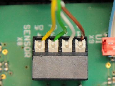
Sensorik
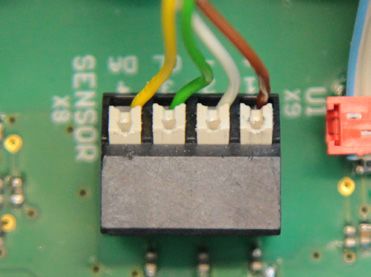
Verwendungszweck Elektrischer Anschluss
Die Sensorik-Module ermöglichen Das Kabel des Sensorik-Moduls ist
die bedarfsgeführte Steuerung zur an die Klemmstelle SENSOR X8
Optimierung des Raumluftklimas der Steuerungsplatine anzuschlie-
und erhöhen somit den Komfort und ßen (Tab.1).
die Lebensqualität in Wohnräumen. Farbcodierung Klemmstelle Signal
Sensorkabel SENSOR X8
Für den vollautomatischen Betrieb braun 1 +
der Lüftungsgeräte ComfoAir 70 weiß 2 -
und ComfoSpot 50 stehen drei
grün 3 CL
Sensorik-Module zur Verfügung:
gelb 4 DA
n FEUCHTE (kombinierter Tab.1: Farbkodierung
Feuchte-/Temperatursensor)
n VOC (VOC-Sensor und
kombinierter Feuchte-/
Temperatursensor)
n CO2 (CO2-Sensor und
kombinierter Feuchte-/
Temperatursensor)
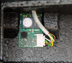
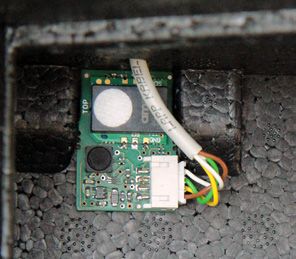
Die Sensorik-Module wer-
den in den Ablufttrakt des
Lüftungsgerätes eingebaut und Installation
detektieren den Abluftzustand
bezüglich Temperatur, relativer Die Montage des
Luftfeuchte, VOC-Konzentration Sensorik-Moduls ist nur im
(volatile Kohlenwasserstoffe) und ausgebauten Zustand des Gerätes
CO2-Konzentration. vorzunehmen. Zum Schutz vor
elektrostatischen Einwirkungen
Die Steuerung der Lüftungsgeräte sollte unbedingt ein ESD-Armband
prüft die Messergebnisse und führt getragen werden.
den je nach Regelcharakteristik er-
forderlichen Regelalgorithmus aus.
4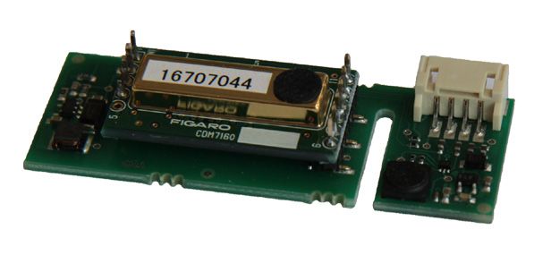
Sensorik

ComfoSpot 50

Nehmen Sie die Innenhaube
Oberschale ab und entnehmen Sie
die Filterverschlüsse und die Filter.
Entnehmen Sie die PVC-
Abdeckung der Steuerungsplatine         Ziehen Sie den Verschlussstopfen
und ziehen Sie vorsichtig               für die Kabeldurchführung im
das Flachbandkabel aus der              Bereich der Steuerplatine aus dem
Steckverbindung UI X9 der               EPP-Gehäuse.
Steuerungsplatine.

                                        Führen Sie das Sensor-Kabel mit
Lösen Sie die vier Muttern für          den Aderenden von innen nach
die Befestigung der Innenhaube          außen durch das EPP-Gehäuse
Unterschale am EPP-Gehäuse              und drücken Sie das Sensor-Kabel
und nehmen Sie die Unterschale          in die Kabelmulde.
inklusive Elektroabdeckung ab.
Ziehen Sie den Enthalpietauscher
aus dem EPP-Gehäuse.

                                        Klemmen Sie das Sensor-Kabel
                                        an die Klemmstelle SENSOR X8
                                        der Steuerungsplatine gemäß
                                        Beschreibung Elektrischer
Klemmen Sie das Sensorik-Modul          Anschluss an.
unter Beachtung der Kabelführung
in die Fixiermulde des EPP-             Montieren Sie alle Teile in umge-
Gehäuses.                               kehrter Reihenfolge.

                                                                            5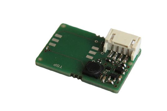
Sensorik

           ComfoAir 70                        das Kabel im Bereich der
                                              Steuerungsplatine endet.
           Nehmen Sie die obere Design-
           Abdeckhaube durch Herausziehen
           ab und schrauben Sie untere
           Design-Abdeckhaube ab.

           Ziehen Sie den oberen Teil des
           EPP-Gehäuses ab und führen
           Sie das Sensor-Kabel mit den       Klemmen Sie das Sensor-Kabel
           Aderenden von innen nach           an die Klemmstelle SENSOR X8
           außen durch das Loch des EPP-      der Steuerungsplatine gemäß
           Gehäuses.                          Beschreibung Elektrischer
                                              Anschluss an.

                                              Montieren Sie alle Teile in umge-
                                              kehrter Reihenfolge.

           Klemmen Sie das Sensorik-Modul
           unter Beachtung der Kabelführung
           in die Fixiermulde des EPP-
           Gehäuses.

           Stecken Sie das obere EPP-
           Gehäuseteil auf das untere auf.
           Verlegen Sie das Sensorkabel
           in der Kabelmulde, so dass

           6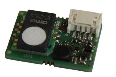
Sensorik

Regelcharakteristik

Bei Anwendung der Automatik-                      Automatik-Funktion des höheren
Funktion werden die Lüfter des                    Sensorsignals.
Gerätes in Abhängigkeit des
Konzentrationsgehaltes der jeweils                Die Bad-Funktion bewirkt die
zu detektierenden Messgröße                       maximale Drehzahl der Lüfter ab
gesteuert.                                        80 % relativer Luftfeuchte. Diese
                                                  spezielle Regelcharakteristik wird
Die Platinen des Sensorik-                        nur bei konfigurierter Automatik-
Moduls VOC und des Sensorik-                      Funktion FEUCHTE-Regelung
Moduls CO2 sind zusätzlich mit                    ausgeführt.
einem kombinierten Feuchte-/
Temperatursensor ausgestattet
und generieren jeweils zwei                       Automatik-Funktion
Sensorsignale, die separat
per DIP-Schalter konfiguriert                     Der vierpolige DIP-Schalter MODE
werden können. Sind beide in                      SW1 dient der Konfiguration der
ON-Position folgen die Lüfter der                 vorgesehenen Automatik-Funktion
Regelcharakteristik der                           des jeweiligen Sensorik-Moduls
                                                  (Tab.2).

         DIP-Schalter Nr.
                                                Aktivierte Automatik-Funktion
    1        2       3       4

   ON      OFF      OFF     OFF     VOC- / CO2-Regelung
   ON       ON      OFF     OFF     VOC- / CO2-Regelung und FEUCHTE-Regelung
   OFF      ON      OFF     OFF     FEUCHTE-Regelung
   OFF      ON      OFF      ON     FEUCHTE-Regelung mit Bad-Funktion
   ON       ON      OFF      ON     VOC- / CO2, FEUCHTE-Regelung mit Bad-Funktion

 Tab.2: Sensorik-Module bei unterschiedlicher DIP-Schalter-Stellung

 * Anmerkung: DIP-Schalter Nr. 3 dient der Konfiguration der Stoßlüftungs-Funktion

                                                                                       7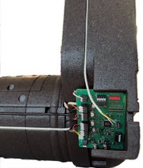
Sensor system

       Intended purpose                         Electrical connection

       The sensor system modules enable         The cable for the sensor system
       the demand-based control panel           module is to be connected to the
       to optimise the indoor air climate,      clamping point for SENSOR X8 on
       increasing comfort and quality of life   the control board (Tab.1).
       in living spaces.                         Colour coding      SENSOR X8        Signal
                                                 for sensor cable   clamping point
       Three sensor system modules are           brown              1                +
       available for the fully automated         white              2                -
       operation of the ComfoAir 70 and          green              3                CL

       ComfoSpot 50 ventilation units:           yellow             4                DA

                                                Tab.1: Colour coding
           n HUMIDITY (combined
             humidity/temperature sensor)
           n VOC (VOC sensor and
             combined humidity/
             temperature sensor)
           n CO2 (CO2 sensor and
             combined humidity/
             temperature sensor)

       The sensor system modules are
                                                Installation
       installed in the exhaust air section
                                                         The sensor system module
       of the ventilation unit and detect
                                                         must be installed before the
       the condition of the exhaust air in
                                                unit is fitted. To provide protection
       terms of its temperature, relative
                                                against electrostatic effects, an
       humidity, VOC concentration
                                                ESD armband must be worn.
       (volatile organic compounds) and
       CO2 concentration.

       The control panel for the ventilation
       units checks the measurement
       results and executes the control
       algorithm required based on the
       control characteristic.

       8
Sensor system

ComfoSpot 50

Take the top cover off the interior
hood and remove the filter caps
and filters.
Remove the PVC cover from the
control board and carefully pull the   Remove the blanking plug for
ribbon cable out of the UI X9 plug     the cable guide in the vicinity of
connection on the control board.       the control board from the EPP
                                       housing.

Undo the four nuts used to fasten
the bottom cover of the interior
hood to the EPP housing and            Guide the sensor cable, together
remove the bottom cover including      with the wire edges, from the
the electronic equipment cover.        inside to the outside through the
Remove the enthalpy exchanger          EPP housing and push the sensor
from the EPP housing.                  cable into the cable recess.

                                       Connect the sensor cable to the
Clamp the sensor system module         clamping point for SENSOR X8
into the fixation recess of the EPP    on the control board as described
housing, bearing in mind the cable     under Electrical connection.
routing.
                                       Install all parts in reverse order.

                                                                             9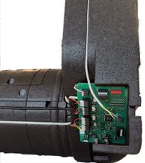
Sensor system

       ComfoAir 70

       Pull the upper front cover out to
       remove it and unscrew the lower
       front cover.

       Pull off the upper part of the EPP
       housing, and guide the sensor          Connect the sensor cable to the
       cable, together with the wire ends,    clamping point for SENSOR X8
       from the inside to the outside         on the control board as described
       through the hole in the EPP            under Electrical connection.
       housing.
                                              Install all parts in reverse order.

       Clamp the sensor system module
       into the fixation recess of the EPP
       housing, bearing in mind the cable
       routing.

       Place the upper part of the EPP
       housing onto the lower part. Install
       the sensor cable in the cable
       recess so that the cable ends in
       the vicinity of the control board.

       10
Sensor system
Control characteristic
When using the Automatic The Bathroom function activates
function, the fans for the unit the maximum fan speed from
are controlled subject to the a relative humidity of 80%. This
concentration of the measured special control characteristic is
variable being detected. only executed if the HUMIDITY
control Automatic function has
The PCBs of the VOC sensor been configured.
system module and the CO2
sensor system module are also
fitted with a combined humidity/ Automatic function
temperature sensor and each
generate two sensor signals, which The four-pin DIP switch MODE
can be configured separately via SW1 is used for the configuration
a DIP switch. If both are in the ON of the designated Automatic
position, the fans follow the control function for the respective sensor
characteristic of the automatic system module (Tab.2).
function with the higher sensor
signal.
DIP switch no.
Activated Automatic function
1 2 3 4
ON OFF OFF OFF VOC / CO2 control
ON ON OFF OFF VOC / CO2 control and HUMIDITY control
OFF ON OFF OFF HUMIDITY control
OFF ON OFF ON HUMIDITY control with Bathroom function
ON ON OFF ON VOC / CO2, HUMIDITY control with Bathroom function
Tab.2: Sensor system modules with various DIP switch positions
* Note: DIP switch no. 3 is used to configure the Boost ventilation function
11Capteurs
Utilisation prévue Raccordement
électrique
Les modules de capteurs permet- Le câble du module de capteurs
tent une régulation en fonction doit être branché au niveau du
des besoins pour optimiser le point de serrage SENSOR X8 de
climat intérieur et améliorer ainsi le la platine de commande (Tab. 1).
confort et la qualité de vie dans les Code couleur Point de Signal
pièces d’habitation. des câbles des serrage
capteurs SENSOR X8
Trois modules de capteurs sont
marron 1 +
disponibles pour le fonctionnement
entièrement automatique des blanc 2 -
appareils de ventilation ComfoAir 70 vert 3 CL
et ComfoSpot 50 :
jaune 4 DA
n HUMIDITE (capteur combiné Tab. 1 : Code couleur
de température et d’humidité)
n COV (capteur de COV et
capteur combiné de tempéra-
ture et d’humidité)
n CO2 (capteur de CO2 et cap-
teur combiné de température
et d’humidité)
Les modules de capteurs sont
installés dans le flux d’air extrait Installation
de l’appareil de ventilation et
détectent l’état de l’air extrait du
Le montage du module de
point de vue de sa température,
capteurs doit uniquement
de son humidité relative, de sa
être effectué alors que
concentration en COV (compo-
l’appareil est démonté. Porter im-
sés organiques volatils) et de sa
pérativement un bracelet antista-
concentration en CO2.
tique pour prévenir les décharges
électrostatiques.
La régulation des appareils de
ventilation vérifie les résultats de
mesure et exécute l’algorithme de
régulation requis selon les caracté-
ristiques de régulation.
12Capteurs
ComfoSpot 50
Retirer la coiffe supérieure du
capot intérieur et enlever les fer-
metures de filtre et les filtres.
Retirer le couvercle en PVC de la
platine de commande et ôter avec Retirer le bouchon à passage de
précaution le câble en nappe du câble dans la zone de la platine de
connecteur UI X9 de la platine de commande du boîtier en EPP.
commande.
Guider le câble des capteurs avec
Desserrer les quatre écrous de
les extrémités des conducteurs de
fixation de la coiffe inférieure
l’intérieur vers l’extérieur à travers
du capot intérieur sur le boîtier
le boîtier en EPP et enfoncer le
en EPP et retirer la coiffe inférieure
câble des capteurs dans la rainure
avec le couvercle du raccordement
de câble.
électrique. Retirer l’échangeur
de chaleur enthalpique du boîtier
en EPP.
Connecter le câble des capteurs
au point de serrage SENSOR X8
de la platine de commande
conformément à la description
Connecter le module de capteurs
du paragraphe Raccordement
en veillant au guidage du câble
électrique.
dans la rainure de fixation du
boîtier en EPP.
Remonter tous les composants
dans l’ordre inverse.
13Capteurs
ComfoAir 70 câble aboutisse dans la zone de la
platine de commande.
Tirer sur le capot de recouvrement
design supérieur pour le retirer et
dévisser le capot de recouvrement
design inférieur.
Retirer la partie supérieure du
boîtier en EPP et guider le câble
des capteurs avec les extrémités Connecter le câble des capteurs
des conducteurs de l’intérieur au point de serrage SENSOR X8
vers l’extérieur à travers le trou du de la platine de commande
boîtier en EPP. conformément à la description
du paragraphe Raccordement
électrique.
Monter tous les composants dans
l’ordre inverse.
Connecter le module de capteurs
en veillant au guidage du câble
dans la rainure de fixation du
boîtier en EPP.
Clipser la partie supérieure du boî-
tier en EPP sur la partie inférieure.
Poser le câble des capteurs dans
la rainure de câble, de sorte que le
14Capteurs
Caractéristiques de
régulation
Lors de l’utilisation de la fonction La fonction bain active la vitesse
automatique, les ventilateurs de de rotation maximale des ven-
l’appareil sont régulés en fonction tilateurs à partir d’une humidité
de la concentration de la grandeur relative de l’air de 80 %. Cette
de mesure qui doit être détectée. caractéristique de régulation spé-
ciale est uniquement exécutée si
Les platines du module de cap- la fonction automatique régulation
teurs COV et du module de cap- HUMIDITE est configurée.
teurs CO2 sont en outre équipées
d’un capteur combiné de tempé-
rature et d’humidité et génèrent Fonction automatique
chacune deux signaux de capteur,
qui peuvent être configurés sépa- Le commutateur DIP à quatre
rément via le commutateur DIP. pôles MODE SW1 sert à la
Si les deux sont en position ON, les configuration de la fonction
ventilateurs suivent les caractéris- automatique prévue du module de
tiques de régulation de la fonction capteurs concerné (Tab. 2).
automatique du signal de capteur
le plus fort.
Commutateur DIP no
Fonction automatique activée
1 2 3 4
ON OFF OFF OFF Régulation COV/CO2
ON ON OFF OFF Régulation COV/CO2 et régulation HUMIDITE
OFF ON OFF OFF Régulation HUMIDITE
OFF ON OFF ON Régulation HUMIDITE avec fonction bain
ON ON OFF ON Régulation COV/CO2 et HUMIDITE avec fonction bain
Tab. 2 : Modules de capteurs avec différentes positions du commutateur DIP
* Remarque : le commutateur DIP no 3 sert à la configuration de la fonction de ventilation forcée.
15Sensori
Impiego previsto Collegamento elettrico
I moduli sensore consentono di Il cavo del modulo sensore va col-
gestire la ventilazione secondo le legato alla morsettiera SENSOR X8
necessità, ai fini dell’ottimizzazione della scheda di comando (tab. 1).
del clima ambientale e quindi del
Codifica colore Morsettiera Segnale
comfort e della qualità di vita negli cavo sensore SENSOR X8
spazi abitativi.
marrone 1 +
Per il funzionamento completa- bianco 2 -
mente automatico dei dispositivi verde 3 CL
di ventilazione ComfoAir 70 e
giallo 4 DA
ComfoSpot 50 sono disponibili tre
Tab.1: codifica colore
moduli sensore:
n UMIDITÀ (sensore combinato
di umidità/temperatura)
n VOC (sensore VOC e sen-
sore combinato di umidità/
temperatura)
n CO2 (sensore CO2 e sen-
sore combinato di umidità/
temperatura)
Installazione
I moduli sensore sono montati
nel tratto di ripresa del dispositivo Il montaggio del modu-
di ventilazione e rilevano lo stato lo sensore va eseguito
dell'aria di ripresa in riferimento a solo con l’apparecchio
temperatura, umidità relativa, con- smontato. A protezione dagli effetti
centrazione di VOC (idrocarburi delle scariche elettrostatiche, va
volatili) e concentrazione di CO2. indossato obbligatoriamente un
bracciale ESD.
L’unità di comando dei dispositivi
di ventilazione elabora i risultati
misurati e regola di conseguenza
l’unità di ventilazione.
16Sensori
ComfoSpot 50
Rimuovere il rivestimento superio-
re della parte interna ed estrarre i
cappucci filtro e i filtri.
Togliere il coperchio in PVC della
scheda di comando e sfilare con
cautela il cavo a nastro piatto dal Estrarre il tappo di fine linea per
collegamento a innesto UI X9 della passare il cavo dall’alloggiamento
scheda di comando. in EPP nell’area della scheda di
comando.
Allentare i quattro dadi per il
fissaggio del telaio interno sull’al- Far passare il cavo del sensore
loggiamento in EPP e rimuovere con i puntalini dall’interno all’ester-
il rivestimento inferiore con il no attraverso l’alloggiamento in
coperchio dei componenti elettrici. EPP e premere il cavo del sensore
Sfilare lo scambiatore entalpico nella scanalatura del cavo.
dall’alloggiamento in EPP.
Collegare il cavo del sensore alla
morsettiera SENSOR X8 della
Collegare il modulo sensore, fa- scheda di comando secondo la de-
cendo attenzione al passaggio del scrizione Collegamento elettrico.
cavo, nella scanalatura di fissaggio
dell’alloggiamento in EPP. Montare tutti i componenti nella
sequenza inversa.
17Sensori
ComfoAir 70
Rimuovere la griglia di copertura
superiore sfilandola e svitare la
griglia di copertura inferiore.
Sfilare la parte superiore dell’al-
loggiamento in EPP e far passare Collegare il cavo del sensore alla
il cavo del sensore con i puntalini morsettiera SENSOR X8 della
dall’interno all’esterno attraverso il scheda di comando secondo la
foro dell’alloggiamento in EPP. descrizione Collegamento elettrico.
Montare tutti i componenti nella
sequenza inversa.
Collegare il modulo sensore, fa-
cendo attenzione al passaggio del
cavo, nella scanalatura di fissaggio
dell’alloggiamento in EPP.
Innestare la parte superiore dell’al-
loggiamento in EPP sulla parte in-
feriore. Posare il cavo del sensore
nella scanalatura del cavo in modo
tale che il cavo termini nella zona
della scheda di comando.
18Sensori
Caratteristiche di
regolazione
In caso di utilizzo della funzione La funzione bagno imposta il
automatica, i ventilatori del dispo- numero dei giri massimo dei
sitivo vengono attivati a seconda ventilatori a partire dall’80% di
della concentrazione della gran- umidità relativa. Questa particolare
dezza da rilevare. caratteristica di regolazione viene
eseguita solo se è configurata la
Le schede del modulo sensore funzione automatica Regolazione
VOC e del modulo sensore CO2 UMIDITÀ.
sono dotate in via supplemen-
tare di un sensore combinato di
umidità/temperatura e generano Funzione automatica
due segnali sensore, configurabili
separatamente tramite interruttori L’interruttore DIP a quattro poli
DIP. Se entrambi sono in posizione MODE SW1 serve a configurare
ON, i ventilatori seguono le carat- la funzione automatica prevista per
teristiche di regolazione della ciascun modulo sensore (tab. 2).
funzione automatica del segnale
sensore più alto.
Interruttore DIP n.
Funzione automatica attivata
1 2 3 4
ON OFF OFF OFF Regolazione VOC/CO2
ON ON OFF OFF Regolazione VOC/CO2 e regolazione UMIDITÀ
OFF ON OFF OFF Regolazione UMIDITÀ
OFF ON OFF ON Regolazione UMIDITÀ con funzione bagno
ON ON OFF ON Regolazione VOC/CO2, UMIDITÀ con funzione bagno
Tab. 2: moduli sensori con diversa posizione dell’interruttore DIP
* Nota: l’interruttore DIP n. 3 serve per la configurazione della funzione di ventilazione intensa
19Sensorsysteem
Gebruiksdoel Elektrische aansluiting
De sensormodules maken een op De kabel van de sensormodule
de behoeften afgestemde regeling moet op de klempositie SENSOR
ter optimalisatie van het binnen- X8 van de besturingsprintplaat
luchtklimaat mogelijk en verhogen worden aangesloten (tab.1).
daarmee het comfort en de levens- Kleurcodering Klempositie Signaal
kwaliteit in woonruimten. sensorkabel SENSOR X8
bruin 1 +
Voor het volautomatische bedrijf van
de ventilatie-units ComfoAir 70 en wit 2 -
ComfoSpot 50 staan drie sensor- groen 3 CL
modules ter beschikking:
geel 4 DA
n VOCHT (gecombineerde Tab.1: Kleurcodering
vocht-/temperatuursensor)
n CO2 (CO2-sensor en gecom-
bineerde vocht-/temperatuur-
sensor)
De sensormodules worden in het
afvoerluchttraject van de ventila-
tie-unit ingebouwd en detecteren
de toestand van de afvoerlucht
Installatie
met betrekking tot de temperatuur,
de relatieve luchtvochtigheid, of de
De montage van de sen-
CO2-concentratie.
sormodule mag alleen in
De besturing van de ventilatie-units uitgebouwde toestand van
analyseert de meetresultaten en het apparaat worden verricht. Ter
voert het voor de regelkarakteristiek bescherming tegen elektrostatische
noodzakelijke regelalgoritme uit. inwerkingen moet absoluut een
ESD-armband worden gedragen.
20Sensorsysteem
ComfoSpot 50
Verwijder de bovenschaal van de
binnenkap en verwijder de filteraf-
dekkingen en de filters.
Verwijder de PVC-afdekking van
de besturingsprintplaat en trek Trek de sluitstop voor de ka-
voorzichtig de lintkabel uit de beldoorvoer ter hoogte van de
insteekverbinding UI X9 van de besturingsprintplaat uit de
besturingsprintplaat. EPP-behuizing.
Maak de vier moeren voor de Voer de sensorkabel met de
bevestiging van de onderschaal adereinden van binnen naar buiten
van de binnenkap aan de EPP- door de EPP-behuizing en druk de
behuizing los en verwijder de on- sensorkabel in de kabelgoot.
derschaal inclusief de elektrische
afdekking. Trek de enthalpiewisse-
laar uit de EPP-behuizing.
Sluit de sensorkabel op het
klempunt SENSOR X8 van de
besturingsprintplaat aan zoals
beschreven bij Elektrische aan-
Klem de sensormodule in de fixa- sluiting.
tiegoot van de EPP-behuizing en
let daarbij op de kabelgeleiding. Monteer alle onderdelen in omge-
keerde volgorde.
21Sensorsysteem
ComfoAir 70
Verwijder de bovenste design-af-
dekkap door deze eruit te trekken
en schroef de onderste design-af-
dekkap los.
Sluit de sensorkabel op het
Trek het bovenste deel van de klempunt SENSOR X8 van de
EPP-behuizing eraf en voer de besturingsprintplaat aan zoals
sensorkabel met de adereinden beschreven bij Elektrische aan-
van binnen naar buiten door het sluiting.
gat van de EPP-behuizing.
Monteer alle onderdelen in omge-
keerde volgorde.
Klem de sensormodule in de fixa-
tiegoot van de EPP-behuizing en
let daarbij op de kabelgeleiding.
Steek het bovenstuk van de
EPP-behuizing op het onderstuk.
Installeer de sensorkabel in de ka-
belgoot zodat deze ter hoogte van
de besturingsprintplaat eindigt.
22Sensorsysteem
Regelkarakteristiek
Bij gebruik van de automatische De badfunctie stelt het maximale
functie worden de ventilatoren van toerental van de ventilatoren in
het apparaat aangestuurd in relatie vanaf 80% relatieve luchtvochtig-
tot de concentratie van de respec- heid. Deze speciale regelkarakte-
tievelijk te detecteren meetfactor. ristiek wordt alleen bij geconfi-
gureerde automatische functie
De printplaten van de sensormo- VOCHT-regeling uitgevoerd.
dules VOC en CO2 zijn tevens
voorzien van een gecombineer-
de vocht-/temperatuursensor Automatische functie
en genereren telkens twee
sensorsignalen, die apart kunnen De vierpolige DIP-schakelaar
worden geconfigureerd via MODE SW1 dient voor de configu-
DIP-schakelaars. Staan beiden ratie van de voorziene automati-
in de ON-positie, dan volgen de sche functie van de betreffende
ventilatoren de regelkarakteristiek sensormodule (tab.2).
van de automatische functie van
het hogere sensorsignaal.
DIP-schakelaar nr.
Geactiveerde automatische functie
1 2 3 4
ON OFF OFF OFF VOC-/CO2-regeling
ON ON OFF OFF VOC-/CO2-regeling en VOCHT-regeling
OFF ON OFF OFF VOCHT-regeling
OFF ON OFF ON VOCHT-regeling met badkamerfunctie
ON ON OFF ON VOC-/CO2-, VOCHT-regeling met badkamerfunctie
Tab.2: Sensormodules bij verschillende DIP-schakelaarstanden
* Opmerking: DIP-schakelaar nr. 3 dient voor de configuratie van de boostventilatiefunctie
23Czujniki
Przeznaczenie Zasilanie elektryczne
Moduły czujników umożliwiają Kabel modułu czujników należy
dopasowaną do potrzeb regulację podłączyć do miejsca mocowania
w celu optymalizacji klimatu SENSOR X8 na płytce sterującej
wnętrza, zwiększając tym samym (tab.1).
komfort cieplny i jakość życia w Kod kolorów Miejsce Sygnał
pomieszczeniach mieszkalnych. kabla czujnika mocowania
SENSOR X8
Do jednostek wentylacyjnych brązowy 1 +
ComfoAir 70 i ComfoSpot 50 biały 2 -
oferowane są trzy moduły czujników
zielony 3 CL
do wyboru, które zapewniają w pełni
automatyczną pracę: żółty 4 DA
Tab. 1: Kod kolorów
n WILGOTNOŚĆ
(połączony czujnik
n wilgotności/temperatury)
LZO (czujnik LZO
i połączony czujnik
wilgotności/temperatury)
n CO2 (czujnik CO2
i połączony czujnik
wilgotności/temperatury)
Moduły czujników są
Instalacja
zamontowane w kanale powietrza
Montaż modułu czujników
wywiewanego i określają jego
można wykonywać tylko
stan na podstawie temperatury,
w zdemontowanym
względnej wilgotności powietrza,
urządzeniu. W celu ochrony przed
stężenia LZO (lotne związki
wyładowaniami elektrostatycznymi
organiczne) i stężenia CO2.
należy koniecznie nosić opaskę
ESD.
Sterowanie jednostek
wentylacyjnych sprawdza wyniki
pomiaru i w zależności od
charakterystyki regulacji wykonuje
wymagany algorytm regulacji.
24Czujniki
ComfoSpot 50
Zdjąć wewnętrzną osłonę górnej
części, mocowania filtra i filtr.
Zdjąć osłonę płytki sterującej
z PVC i ostrożnie odczepić kabel
płaski od złącza wtykowego UI X9 Wyjąć zaślepkę z obudowy EPP
płytki sterującej. w miejscu montażu przepustu
kablowego w obszarze płytki
sterującej.
Poluzować cztery nakrętki
mocujące wewnętrzną osłonę
dolnej części do obudowy EPP,
a następnie zdjąć dolną część Poprowadzić kabel czujnika
razem z osłoną przewodów z końcówkami żył od wewnątrz
elektrycznych. Wyjąć entalpiczny na zewnątrz poprzez obudowę
wymiennik ciepła z obudowy EPP. EPP, a następnie wcisnąć kabel
czujnika w rynienkę kablową.
Podłączyć moduł czujników, Podłączyć kabel czujnika do
zwracając uwagę na prowadnicę miejsca mocowania SENSOR
kablową w rynience mocującej X8 na płytce sterującej zgodnie
w obudowie EPP. z opisem złącza elektrycznego.
Zamontować wszystkie części
wykonując czynności w odwrotnej
kolejności.
25Czujniki
ComfoAir 70
Pociągnąć i zdjąć górną obudowę,
a następnie odkręcić dolną.
Zdjąć górną część obudowy EPP
i wyprowadzić kabel czujnika
z końcówkami żył od wewnątrz Podłączyć kabel czujnika do
na zewnątrz poprzez otwór miejsca mocowania SENSOR X8 na
w obudowie EPP. płytce sterującej zgodnie z opisem
złącza elektrycznego.
Zamontować wszystkie części
wykonując czynności w odwrotnej
kolejności.
Podłączyć moduł czujników,
zwracając uwagę na prowadnicę
kablową w rynience mocującej
w obudowie EPP.
Podłączyć górną część obudowy
EPP do dolnej. Ułożyć kabel
czujnika w rynience kablowej tak,
aby kończył się on przy płytce
sterującej.
26Czujniki
Charakterystyka
regulacji
W przypadku korzystania z funkcji Funkcja łazienkowa powoduje
automatycznej sterowanie osiągnięcie maksymalnej
wentylatorami urządzenia odbywa prędkości obrotowej przez
się w zależności od stopnia stężenia wentylator przy względnej
określonej wielkości pomiarowej. wilgotności powietrza powyżej
80%. Ta specjalna charakterystyka
Płytki drukowane modułu regulacji występuje tylko przy
czujników LZO i modułu czujników skonfigurowanej automatycznej
CO2 są dodatkowo wyposażone funkcji regulacji WILGOTNOŚCI.
w połączony czujnik wilgotności/
temperatury i wysyłają po dwa
sygnały z czujników, które Funkcja automatyczna
można osobno skonfigurować
za pomocą przełącznika DIP. 4-stykowy przełącznik DIP MODE
Jeśli oba znajdują się w pozycji SW1 służy do konfiguracji funkcji
ON, wentylatory pracują zgodnie automatycznej danego modułu
z charakterystyką regulacji czujników (tab. 2).
automatycznej funkcji wyższego
sygnału czujnika.
Nr przełącznika DIP
Aktywowana funkcja automatyczna
1 2 3 4
ON OFF OFF OFF Regulacja LZO / CO2
ON ON OFF OFF Regulacja LZO / CO2 i regulacja WILGOTNOŚCI
OFF ON OFF OFF Regulacja WILGOTNOŚCI
OFF ON OFF ON Regulacja WILGOTNOŚCI z funkcją łazienkową
Regulacja LZO / CO2, regulacja WILGOTNOŚCI
ON ON OFF ON
z funkcją łazienkową
Tab. 2: Moduł czujników w zależności od ustawienia przełącznika DIP
* Wskazówka: Przełącznik DIP nr 3 służy do konfiguracji funkcji przewietrzania.
27Deutschland France The Netherlands
Zehnder Group Deutschland Zehnder Group France Zehnder Group Nederland B.V.
GmbH 3 rue du Bois Briard Lingenstraat 2
Almweg 34 91080 Courcouronnes 8028 PM Zwolle
77933 Lahr
T +49 7821 586 0 T +33 169 361 646 T +31 38 42 96 911
F +49 7821 586 223 F +33 169 474 581 F +31 38 42 25 694
PDE-Installation Notes_CS50/CA70_Sensor system_V1.0,V1217_DE,EN,FR,IT,NL,PL_subject to change
info@zehnder-systems.de comfosystems.france@zehn- info@jestorkair.nl
www.zehnder-systems.de www.jestorkair.nl
dergroup.com
www.comfosystems.fr
Great Britain Italy Poland
Zehnder Comfosystems UK Ltd Zehnder Tecnosystems S.r.l. Zehnder Polska Sp. z o.o.
Unit 1, Brookside Avenue Via XXV Luglio, 6 ul. Kurpiów 14a
Rustington West Sussex Campogalliano (MO) 41011 52-214 Wrocław
BN16 3LF
T +44 1903 777 333 T +39 059 978 62 00 T +48 71 367 64 24
F +44 1903 782 398 F +39 059 978 62 01 F +48 71 367 64 25
comfosystems@zehnder.co.uk info@comfosystems.it wentylacja@zehnder.pl
www.zehnder.co.uk www.comfosystems.it www.zehnder.pl
United States Switzerland Sales International
Zehnder America Inc. Zehnder Comfosystems Zehnder Group Deutschland
540 Portsmouth Avenue Cesovent AG GmbH
Almweg 34
Greenland, NH 03840 Zugerstrasse 162
77933 Lahr
8820 Wädenswil
Deutschland
T +1 603 422 6700 T +41 43 833 20 20 T +49 7821 586-392
F +1 603 422 9611 F +41 43 833 20 21 F +49 7821 586-406
info@zehnderamerica.com info@zehnder-comfosystems.ch sales.international@zehnder-
group.com
www.zehnderamerica.com www.zehnder-comfosystems.ch
www.international.zehnder-
systems.comSie können auch lesen