HDMI Control Basic 4K60 Inbetriebnahme- und Bedienungsanleitung Commissioning and operating instructions - D GB - Estalella Audiovisual
←
→
Transkription von Seiteninhalten
Wenn Ihr Browser die Seite nicht korrekt rendert, bitte, lesen Sie den Inhalt der Seite unten

HDMI Control Basic 4K60
 HDMI Mediensteuerung zur automatischen Display Steuerung
 HDMI Auto-Sensing Display Control

 Art.-Nr. 5778000151
 Ref.-No. 5778 000 151

 Inbetriebnahme- und Bedienungsanleitung
 Commissioning and operating instructions

  D
 GB
07.2020

D

Inhaltsverzeichnis

1.       Vorwort .............................................................................................................................................. 3

2.       Sicherheitshinweise und Vorsichtsmaßnahmen ................................................................................ 3

3.       Gerätebeschreibung / Bestimmungsgemäße Verwendung ............................................................. 4
         3.1. Eigenschaften ............................................................................................................................ 4
         3.2. Lieferumfang ............................................................................................................................. 4

4.       Bedien- und Anzeigekomponenten .............................................................................................. 5 - 6
         4.1. Vorderseite ................................................................................................................................ 5
         4.2. Rückseite ................................................................................................................................... 6

5.       Anschlussschema .............................................................................................................................. 7

6.       Funktion der DIP-Schalter ............................................................................................................. 8 - 9
         6.1. EDID Management ..................................................................................................................... 8
           6.1.1. Benutzerdefinierte EDID Einstellung ................................................................................... 9
         6.2. HDCP Modus .............................................................................................................................. 9

7.       Aktivieren der Mediensteuerungsfunktionen  ........................................................................... 10 - 16
         7.1. SYSTEM EIN ............................................................................................................................... 10
         7.2. SYSTEM AUS .............................................................................................................................. 10
         7.3. RS232-Befehlseinstellung ......................................................................................................... 10
           7.3.1. Einstellung der Trigger-Methode ....................................................................................... 11
           7.3.2. Einstellung der CEC-Steuerung ......................................................................................... 12
           7.3.3. Konfigurieren der RS232 Steuerung .......................................................................... 12 - 13
           7.3.4. Einstellung der IR-Steuerung ............................................................................................ 14
           7.3.5. IR-Codes über die Empfangsdiode im Frontpanel anlernen ............................................ 15
           7.3.6. Einstellung der Relaissteuerung ....................................................................................... 15
           7.3.7. Beschreibung des Relaisanschlusses ................................................................................ 16
           7.3.8. Systembefehle ........................................................................... ....................................... 16

8.       Firmware Upgrade ........................................................................................................................... 16

9.       Technische Daten ............................................................................................................................. 17

10. Fehlerbehebung ............................................................................................................................... 18

11. CE-Konformitätserklärung ............................................................................................................... 18

12. Verfügbares Zubehör ....................................................................................................................... 19

2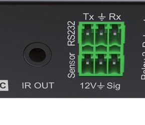
1. Vorwort
Bevor Sie das Produkt verwenden, lesen Sie diese Bedienungsanleitung sorgfältig durch. Die in diesem
Handbuch gezeigten Bilder dienen nur als Referenz und können sich vom realen Produkt unterscheiden.
Dieses Handbuch dient nur als Bedienungsanleitung. Wenden Sie sich an den örtlichen Händler, um
Unterstützung bei der Wartung zu erhalten.
Im ständigen Bemühen, das Produkt zu verbessern, behalten wir uns das Recht vor, Funktionen oder
Parameter ohne vorherige Ankündigung oder Verpflichtung zu ändern. Die neuesten Informationen
erhalten Sie von Ihrem Kindermann Fachhändler.

2.      Sicherheitshinweise und Vorsichtsmaßnahmen
•    Lesen Sie die Bedienungsanleitung sorgfältig durch und bewahren Sie diese auf.
•    Packen Sie das Gerät vorsichtig aus und heben Sie die Originalverpackung und das Verpackungs-
     material für einen eventuellen späteren Versand auf.
•    Befolgen Sie die grundlegenden Sicherheitsvorkehrungen, um die Gefahr von Bränden,
     Stromschlägen und Verletzungen von Personen zu verringern.
•    Öffnen oder modifizieren Sie niemals das Gerät. Dies kann zu Stromschlägen oder Verbrennungen
     führen.
•    Das Produkt darf nur mit Sicherheitskleinspannung mit dem mitgelieferten Netzteil betrieben werden.
•    Die Verwendung von Verbrauchsmaterialien oder Teilen, die nicht den Produktspezifikationen
     entsprechen, kann zu Beschädigung oder Fehlfunktion führen.
•    Wenden Sie sich bei allen Wartungsarbeiten an qualifiziertes Servicepersonal.
•    Das System darf nur in trockener Umgebung gelagert und eingesetzt werden.
•    Stellen Sie das Gerät an einem gut belüfteten Ort auf, um Schäden durch Überhitzung zu vermeiden.
•    Verwenden Sie zum Reinigen dieses Geräts keine Flüssigkeits- oder Aerosolreiniger.
     Ziehen Sie vor dem Reinigen immer den Netzstecker aus der Steckdose.
•    Ziehen Sie den Netzstecker, wenn Sie das Gerät längere Zeit nicht benutzen.
•    Hinweise zur Entsorgung von Altgeräten: Das Gerät darf nicht mit dem Hausmüll entsorgt werden,
     sondern ist über den Handelsweg zurück zu geben.
•    Vergewissern Sie sich vor der Installation, dass alle Komponenten und Zubehörteile enthalten sind.
•    Alle Netzschalter, Stecker, Steckdosen und Netzkabel müssen isoliert und sicher sein.
•    Alle Geräte sollten vor dem Einschalten angeschlossen werden.

                                                                                                       3
3. Gerätebeschreibung
Die HDMI Control Basic 4K60 vereint eine automatische Mediensteuerung mit einem Signalverstärker
für HDMI. Das Produkt eignet sich ideal für kleine Besprechungsräume, Mittelzonen, Klassenzimmer, etc.
Die HDMI Control Basic 4K60 aktiviert automatisch die Medientechnik im Raum sobald sie entweder
ein HDMI Signal (5V oder TMDS) oder das IR-Signal einer Fernbedienung erkennt. Die Mediensteuerung
sendet dann vorab hinterlegte CEC-, RS232- und/oder IR-Befehle beispielsweise an ein Display oder einen
Projektor. Zusätzlich können über Relaiskontakte auch eine Leinwand oder ein Lift sowie Gewerke aus der
Gebäudetechnik (z. B. Jalousien) gesteuert werden. Bei Signalverlust wird die Technik auf dem gleichen
Weg nach einem festgelegten Interval deaktiviert.

3.1 Eigenschaften
•   Mediensteuerung per CEC, RS232, IR und Relaiskontakten
•   Kontakteingang zum Anschluss von Sensoren und Schaltern
•   Unterstützt 4K2K@60Hz 4:4:4 inkl. HDR10 und Dolby Vision
•   Unterstützt HDCP 1.4, HDCP 2.2, HDCP Downgrade auf 1.4 und HDCP-PASS-Through
•   Unterstützt Down-Scaling von 4K auf 1080P
•   Umfassendes EDID-Management
•   Ein eingebauter „Signal Equalizer” zur Regenerierung von HDMI-Signalen

3.2 Lieferumfang
•    1 x HDMI Control Basic 4K60
•   2 x Montagewinkel mit 4 Schrauben
•   4 x Gerätefüße
•    1 x RS232 Kabel (3-Pin auf 9-Pin SubD)
•   3 x 3-Pin Klemmanschluss Euroblock
•    1 x IR Emitterkabel (1,5 m)
•   1 x Netzteil (12VDC, 1A)
•   1 x Bedienungsanleitung

    Hinweis:
Bitte setzen Sie sich sofort mit Ihrem Händler in Verbindung, wenn bei Erhalt ein Schaden oder Fehlteile
bzgl. der Komponenten festgestellt wird.

4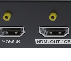
4. Bedien- und Anzeigekomponenten
4.1 Vorderseite

                   1     2     3      4     5      6             7        8

 Nr.   Name                  Beschreibung

  1    Power LED             Bei anliegender Spannung leuchtet die LED grün.

  2    HDMI OUT LED          Wird ein HDMI Signal ausgegeben leuchtet die LED blau.

  3    SENSOR                Eingebauter IR-Sensor zum Lernen/Empfang eines IR-Signals.

                             Die LED blinkt im IR-Lernmodus und leuchtet blau, nachdem der IR-Befehl
  4    DISPLAY ON LED
                             erfolgreich angelernt wurde.
                             Die LED blinkt im IR-Lernmodus und leuchtet blau, nachdem der IR-Befehl
  5    DISPLAY OFF LED
                             erfolgreich angelernt wurde.

  6    Set                   Drücken Sie die Taste, um den IR-Lernmodus zu aktivieren (Details siehe 7.3.5).

  7    4-poliger DIP Schalter Zur Konfiguration der EDID und zur Auswahl des HDCP-Modus.

  8    FW                    Typ-A USB-Anschluss für die Firmware-Aktualisierung.

                                                                                                           5
4.2 Rückseite

                                                     4

                       1         2         3         5         6         7

Nr.     Name               Beschreibung

    1   HDMI IN            HDMI-Eingang (Typ A) zum Anschluss eines HDMI-Quellgerätes, z. B. PC

                           HDMI-Ausgang (Typ A) für den Anschluss eines Wiedergabegeräts, z. B.
    2   HDMI OUT/CEC
                           Display/Projektor, unterstützt CEC
                           3,5 mm Klinkenbuchse zum Anschluss des IR-Senders um IR-Signale zu
    3   IR OUT
                           senden
                           3-polig, zum Aufspielen der Programmierung (z. B. via PC) bzw. im Betrieb
    4   RS232
                           zur Steuerung des Wiedergabegeräts per RS232-Befehlen, z. B. Projektor
                           3-polig, zum Anschluss eines Sensors, Bewegungsmelders (Zubehör)
    5   Sensor

                           2x 3-polig zum Anschluss eines Relais, z. B. zur Steuerung einer Leinwand
    6   Relay 1+2
                           (NO: normaly Open, C: Common, NC: normaly Close).

    7   DC 5V              Hohlstecker zum Anschluss des Netzteils.

6
5. Anschlussschema
Die folgende Skizze zeigt typische Ein- und Ausgangsgeräte, die mit dem HDMI Control Basic 4K60
gesteuert werden können:

                                                                          ▼

                                                                                       ⚫
                                                                                   �
                                                           ⚫
                               ⚫               ⚫       ⚫       ⚫
                                          ⚫

                                                                                         IR Detector
            ▼
                                    CEC   ▼   ▼IR          ▼   ▼
                                               ⚫Emitter

            ⚫
                                              �
                                                           ⚫
                                          ⚫

                                                                               ⚫

                                                   Projektor

             Laptop

 ControI:
   HDMI:
                                                                              Leinwand

   Hinweis: Diese Abbildung dient nur als Referenz.

                                                                                                       7
6. Funktion der DIP-Schalter
6.1 EDID Management
Die EDID (Extended Display Identification Data) wird vom Quellgerät (z. B. Notebook) verwendet, um die
Videoauflösung an den angeschlossenen Bildschirm anzupassen. Standardmäßig wird diese Information
aus dem Speicher des Wiedergabegeräts (z. B. Bildschirm) ausgelesen. Mittels der DIP-Schalter auf der
Vorderseite können auch die voreingestellten EDIDs genutzt werden, um beispielsweise die Kompatibilität
der Videoauflösung sicherzustellen. Die untere Position des Schalters repräsentiert die OFF ("0"), die
obere die ON ("1") Position.

Die DIP Schalter 1-3 dienen der EDID Einstellung. Die Konfiguration ist zusätzlich auf der Rückseite des
Geräts aufgedruckt.

    Schalter Status       Videoauflösung                                    Audio Format
    000                                                       Pass Through
    001                   1080P                                            2-Kanal
    010                   1080P                                            Multi-Kanal
    011                   3840x2160@30Hz HDR                               2-Kanal
    100                   3840x2160@30Hz HDR                               Multi-Kanal
    101                   3840x2160@60Hz HDR                               2-Kanal
    110                   3840x2160@60Hz HDR                               Multi-Kanal
    111                                         Benutzerdefinierte EDID (siehe Punkt 6.1.1)

          Hinweis:
•         2-Kanal: Unterstützt LPCM 2CH
•         Multi-Kanal: Unterstützt LPCM 8CH, Dolby TrueHD, DTS-HD , Dolby Digital5.1, DTS 5.1, Dolby Digital
          Plus

8
6.1.1 Benutzerdefinierte EDID speichern
1.    Benennen Sie die benutzerdefinierte EDID Datei in EC_11.bin um.
2.    Schließen Sie den FW-Port des HDMI Control Basic 4K60 mit einem USB-Kabel an den PC an und
      schalten Sie die HDMI Control Basic 4K60 ein. Der PC erkennt automatisch eine virtuelle Festplatte
      namens "BOOTDISK".
3.    Mit einem Doppelklick öffnen Sie den Datenträger, eine Datei namens "READY.TXT" wird angezeigt.
4.    Kopieren Sie die benutzerdefinierte EDID auf die "BOOTDISK"-Festplatte.
5.    Öffnen Sie den Datenträger erneut, um zu prüfen, ob der Dateiname "READY.TXT" automatisch zu
      "SUCCESS.TXT" umbenannt wurde. Wenn ja, wurde die benutzerdefinierte EDID importiert und als
      benutzerdefinierte EDID (DIP 111) erfolgreich gespeichert.
6.    Entfernen Sie das USB-Kabel und starten Sie den HDMI Control Basic 4K60 neu.
7.    Jetzt kann die neue EDID aufgerufen werden, indem der DIP-Schalter-Status auf "111" gesetzt wird.

     Hinweis:
Das Ablegen einer benutzerdefinierten EDID kann beispielsweise hilfreich sein, wenn über einen HDMI
Verteiler mehrere Wiedergabegeräte (Displays, Projektoren, etc.) angeschlossenen sind, von unterschied-
lichen Herstellern stammen oder unterschiedliche Spezifikationen aufweisen.
Wenn Sie das Wiedergabegerät zur Verfügung haben, die EDID Datei aber nicht vorliegt, können Sie
diese selbst erstellen:
Laden und installieren Sie eine EDID Software auf Ihren PC (z. B. Moninfo), verbinden Ihren PC mit dem
gewünschten Endgerät per HDMI Kabel und lesen die EDID mit dem Starten der Software aus. Bitte
achten Sie dabei darauf, dass Sie z. B. bei Verwendung eines Notebooks das richtige Display ausgewählt
haben. Die EDID Information können Sie nun direkt als EC_11.bin abspeichern.

6.2 HDCP Modus
Stellen Sie den DIP-Schalter 4 auf "ON", um HDCP-Management zu aktivieren.

 Schalter Status     Mode                 HDCP
 OFF (0)             Passiv (Default)     Übernimmt automatisch der HDCP-Version des Quellgerätes
                                          •   Wenn das Eingangsvideo HDCP-Inhalte enthält,
                                              ist die HDCP-Version des HDMI-Ausgangs HDCP 1.4
 ON (1)              Aktiv
                                          •   Wenn das Eingangsvideo keinen HDCP-Inhalt hat,
                                              hat auch der HDMI-Ausgang keinen HDCP-Inhalt

                                                                                                           9
7. Aktivieren der Mediensteuerungsfunktionen
7.1 SYSTEM EIN
Wenn die HDMI Control Basic 4K60 ein Videosignal (TMDS, 5 V) oder ein IR-Signal erkennt (Trigger),
startet das System und führt gleichzeitig die folgenden Aktionen automatisch aus:
•     Sendet "TV On" via CEC zum Einschalten des Anzeigegerätes
•     Sendet "TV On" via RS232 (+ Delay (Standard 3s, einstellbar von 1 - 180s) und ein benutzerdefiniertes
      RS232 Kommando)
•     Sendet "TV On" via IR (+ Delay (Standard 3s, einstellbar von 1 - 180s) und ein benutzerdefiniertes IR
      Kommando)
•     Umschalten des Relais 1 wie folgt, jeweils bezogen auf 'C=Common‘
                                                                       Relaisstatus
    I/O Status
                         NO                              NC
    On (Geschlossen)     Geschlossen                     Offen
    Off (Offen)          Offen                           Geschlossen

7.2 SYSTEM AUS
Die HDMI Control Basic 4K60 erkennt, wenn das HDMI Signal entfernt wurde oder kein IR-Signal inner-
halb der definierten Verzögerungszeit empfangen wird. Dann schaltet das System automatisch ab und
führt die folgenden Aktionen gleichzeitig aus:
•     Senden "TV Off" via CEC zum Ausschalten des Displays
•     Sendet den hinterlegten "TV Off" Befehl via RS232 an das Display/Projektor
      (Wiederholung kann aktiviert werden)
•     Sendet den hinterlegten "TV Off" Befehls via IR an das Display/Projektor
      (Wiederholung kann aktiviert werden)
•     Umschalten des Relais 2 (vergleiche Relais 1, siehe oben)

   Hinweis: Die Standardverzögerung ist mit 10 Minuten voreingestellt, der einstellbare Zeitbereich liegt
zwischen 5 - 180 Minuten, siehe 7.3.1.

7.3 RS232-Befehlseinstellung
Die Trigger Methoden für SYSTEM EIN oder SYSTEM AUS sowie die Befehle für CEC, RS232, IR und Relais-
kontakte müssen per RS232-Kommandos programmiert werden. Dazu wird ein Programm wie
z. B. Docklight oder HTerm benötigt. Bitte stellen Sie in diesen Programmen die richtigen Kommunikati-
onsparameter wie COM-Port, Baudrate, etc. ein, dann können Sie mit der Programmierung beginnen.
                                   Tx GND Rx
     RS232 am Gerät
                                                                       Hinweis:
     Baud rate: 9600
                                                                   Falls Sie nur ASCII Befehle für Ihr zu steuerndes
     Data bit: 8
                                                                   Gerät zur Verfügung haben, können Sie diese in HEX
     Stop bit: 1                                                   umrechnen und als HEX Befehl senden.
     Parity bit: keine                                             Gleiches gilt, wenn der Befehl einen Delimiter benö-
                                                                   tigt, dieser muss an den zu sendenden HEX Befehl
                           5                         1
        RS232-Buchse                                               angehängt werden.
             PC                9                 6
                                                                   Für das Umrechnen von ASCII in HEX bietet sich
                                                                   beispielsweise ein Programm wie ‚Docklight‘ an.
                                     Sub-D9
                                   RS232-Kabel
10
7.3.1 Einstellung der Trigger-Methode
Befehl Funktion Befehlsbeispiel einer Antwort
Einstellung der Triggermethode bei System On
X Beschreibung SYSONMETH1.
0 Empfangen eines IR Signals
SYSONMETH[X]. Aktives HDMI video Signal am
1 Eingang (Standard 5V, oder
TMDS) Ein aktives Video Signal oder ein
IR Signal fungiert als Trigger für
Empfangen von IR oder System On.
2
Video Signal
Ausgabe der Triggermethode vom System Off
X Beschreibung
SYSOFFMETH1.
0 Kein Empfangen eines IR Signals
SYSOFFMETH[X]. Kein aktives HDMI Video Signal
1 am Eingang (Standard 5V, oder
TMDS)
Ein fehlendes Video oder IR Signal
Kein Empfangen von IR oder fungiert als Trigger für System Off.
2
Video Signal
Stellen Sie die Ausschaltverzögerung des
Systems 'sssss' in Sekunden ein (Standard 10 NOSIGDLY:00300.
Minuten = 00600), Einstellbereich von 5 bis 180
NOSIGDLY:[XXXXX]. Minuten).
Wenn kein HDMI-Videosignal erkannt wurde, Die Ausschaltverzögerung bzgl.
schaltet sich das System nach der eingestellten HDMI Signale ist auf 300 Sekunden
Zeit aus! eingestellt.
Stellen Sie die Ausschaltzeit des Systems 'sssss' NOIRDLY:00300.
ein (Standard 10 Minuten = 00600), Einstellbe-
NOIRDLY:[XXXXX]. reich von 5 bis 180 Minuten).
Die Ausschaltverzögerung bzgl.
Wenn kein IR-Signal erkannt wurde, schaltet sich IR Signale ist auf 300 Sekunden
das System nach der Einstellzeit aus. eingestellt.
Einstellen der Auslösebedingung für das
HDMI-Videosignal 5VORTMDS0.
X Beschreibung
5VORTMDS[X].
0 Erkennen des Hotplug Signals
Erkennen einer Eingangsquelle (5V!)
1 Erkennen des Bildsignals (TMDS)
GSYSONMETH. Ausgabe der Triggermethode vom SYSTEM ON. VIDEO TRIGGER FOR SYSTEM ON!
NO VIDEO TRIGGER FOR SYSTEM
GSYSOFFMETH. Ausgabe der Triggermethode vom SYSTEM OFF.
OFF!
Ausgabe der Verzögerungszeit von SYSTEM
DETECT NO SIGNAL DELAY TIME
GNOSIGDLY. OFF, wenn der Controller kein Eingangsquellen-
300S!
signal erkennt (5 V / TMDS)..
11Ausgabe der Verzögerungszeit von SYSTEM
GNOIRDLY. OFF, wenn der Controller kein IR-Sensorsignal DETECT NO IR DELAY TIME 300S!
erkennt.
Ausgabe der Erkennungsmethode der Eingangs-
G5VORTMDS. DETECT INPUT SOURCE USE 5V!
quelle (5V/TMDS)
7.3.2 Einstellung der CEC-Steuerung
Befehl Funktion Befehlsbeispiel einer Antwort
CECON. Aktivieren der CEC Steuerung OPEN CEC FUNCTION!
CECOFF. Deaktivieren der CEC Steuerung CLOSE CEC FUNCTION!
GCECSTAUS. Statusmeldung CEC CEC FUNCTION IS OPEN!
TVON. Einschalten des Displays (z. B. TV) CEC TV POWER ON!
TVOFF. Ausschalten des Displays (z. B. TV) CEC TV POWER OFF!
7.3.3 Konfigurieren der RS232 Steuerung
Befehl Funktion Befehlsbeispiel einer Antwort
Wenn ein Auslösesignal erkannt wird, sende
automatisch den ASCII-Befehl xxx an das
zu steuernde Gerät (z. B. Projektor), dessen
Baudrate x ist.
RS232ON/+3:123abc
X Baudrate
1 2400
RS232ON/+[X]:XXX 2 4800
3 9600
4 19200
Sendet den ASCII Befehl “123abc”
5 38400 an das Fremdgerät (z. B. Projektor)
mit der Baudrate 9600.
6 57600
7 115200
RS232ON/-3:30 31 32
Wenn ein Auslösesignal erkannt wird, sende
RS232ON/-[X]:XXX automatisch den HEX-Befehl XXX an das Fremd- Sendet den HEX Befehl “30 31 32”
gerät (z. B. Projektor), dessen Baudrate X ist. an das Fremdgerät (z. B. Projektor)
mit der Baudrate 9600.
12RS232OFF/+3:123abc
Wenn kein Signal mehr anliegt, sende automa-
RS232OFF/+[X]:XXX tisch den ASCII-Befehl xxx an das zu steuernde Sendet den ASCII Befehl “123abc”
Gerät (z. B. Projektor), dessen Baudrate x ist. an das Fremdgerät (z. B. Projektor)
mit der Baudrate 9600.
RS232OFF/-3:30 31 32
Wenn kein Signal mehr anliegt, sende automa-
RS232OFF/-[X]:XXX tisch den HEX-Befehl xxx an das zu steuernde Sendet den HEX Befehl “30 31 32”
Gerät (z. B. Projektor), dessen Baudrate x ist. an das Fremdgerät (z. B. Projektor)
mit der Baudrate 9600.
RS232USER/+3:123abc
Mit diesem Befehl können Sie einen benutzerde-
finierten ASCII-Befehl xxx nach dem Einschalten Sendet den benutzerdefinierten
RS232U/+[X]:XXX
an das Fremdgerät (z. B. Projektor) mit der ASCII Befehl “123abc” an das
Baudrate X senden. Fremdgerät (z. B. Projektor) mit der
Baudrate 9600.
RS232USER/-3:30 31 32
Mit diesem Befehl können Sie einen benutzerde-
finierten HEX-Befehl xxx nach dem Einschalten Sendet den benutzerdefinierten
RS232U/-[X]:XXX
an das Fremdgerät (z. B. Projektor) mit der ASCII Befehl“30 31 32” an das
Baudrate X senden. Fremdgerät (z. B. Projektor) mit der
Baudrate 9600.
RS232DLY:003.
Einstellen der Sendeintervallzeit zwischen RS232
RS232DLY:[XXX]. ON und RS232 USER auf xxx ein (Standard 3s, Setzt die Verzögerung zwischen
Einstellbereich von 1s bis 180s). RS232 ON und RS232 USER auf
3 Sekunden.
Einstellen der Wiederholungen des RS232OFF
Befehls. RS232PCS1.
X Beschreibung
RS232PCS[X].
0 1 mal
Setzt die Wiederholungen des
1 2 mal RS232OFF Befehls auf 2.
RS232OFFINT:02.
Einstellen der Verzögerung zwischen den RS232
RS232OFFINT:[XX]. OFF Befehlen in xx Sekunden (Standard 2s, Setzt die Verzögerung zwischen
Einstellbereich von 1s bis 10s). den Wiederholungen des RS232OFF
Befehls auf 2 Sekunden.
RS232DLY:003.
Ausgabe der Verzögerung zwischen RS232 ON Die Verzögerung zwischen RS232
GRS232DLY.
und RS232 USER. ON und RS232 USER beträgt 3
Sekunden.
RS232PCS1.
Ausgabe der Anzahl der Widerholungen von
GRS232PCS. Die Anzahl der Wiederholungen des
RS232 OFF
RS232OFF Befehls beträgt 2.
RS232OFFINT:02.
Ausgabe der zweifachen Sendeintervallzeit von Die Verzögerung zwischen den Wie-
GRS232OFFINT.
RS232 OFF derholungen des RS232OFF Befehls
beträgt 2 Skunden.
137.3.4 Einstellung der IR-Steuerung
Befehl Funktion Antwort
Lernt den IR-Befehl von der IR-Fernbedienung.
X Beschreibung IRSTUDY0.
0 Anlernen IR TV PWR Off
IRSTUDY[X]. 1 Anlernen IR TV PWR On
2 Anlernen IR User Für die nächsten 10 Sekunden ist
der Empfänger bereit den IR Befehl
für Power Off des Fremdgerätes zu
Bitte ca. 10 Sekunden nach der RS232 Antwort
lernen.
den IR Befehl an den IR Empfänger senden.
Senden des gelernten IR-Befehls.
X Beschreibung IRSEND0.
IRSEND[X]. 0 Senden IR TV PWR Off
1 Senden IR TV PWR On Der IR Befehl zum Ausschalten des
2 Senden IR User Fremdgerätes wird gesendet.
Einstellen der Verzögerung zwischen IR TV ON IRDLY:003.
IRDLY:[XXX]. und IR TV User auf xxx Sekunden (Standard 3s,
Einstellbereich von 1s bis 180s). Die Verzögerung zwischen IR TV ON
und IR TV USER beträgt 3 Sekunden.
Setzt die Sendezahl von IR OFF auf X.
IRPCS1.
X Beschreibung
IRPCS[X].
0 1 mal
1 2 mal Die Anzahl der Wiederholungen des
IR TV PWR Off Befehls beträgt 2.
IROFFINT:02.
Einstellen der Verzögerung zwischen den IR TV
IROFFINT:[XX]. PWR Off Befehlen in xx Sekunden (Standard 2s, Setzt die Verzögerung zwischen
Einstellbereich von 1s bis 10s). den IR TV PWR Off Befehlen auf
2 Sekunden.
Abfrage der eingestellten Sendeintervallzeit IRDLY:003.
GIRDLY. zwischen dem IR TV PWR On Befehl und IR TV Die Verzögerung zwischen IR TV ON
User. und IR TV USER beträgt 3 Sekunden.
IRPCS1.
Abfrage der eingestellten Anzahl der zu sen-
GIRPCS. Die Anzahl der Wiederholungen des
denden IR TV PWR Off Befehle.
IR TV PWR Off Befehls beträgt 2.
IROFFINT:02.
Abfrage der eingestellten Sendeintervallzeit von
GIROFFINT. Die Verzögerung zwischen den IR TV
IR TV PWR Off.
OFF Befehlen beträgt 2 Sekunden.
147.3.5 IR-Codes über die Empfangsdiode im Frontpanel anlernen
Die IR-Befehle können auch mittels IR-Fernbedienung und SET-Taste auf der Frontplatte angelernt werden.
Zum Erlernen der IR-Befehle von der IR-Fernbedienung gehen Sie bitte wie folgt vor:
Schritt 1:
SET-Taste drücken, um den Befehl DISPLAY ON oder DISPLAY OFF zu wählen.
• DISPLAY ON LED: Blinken zeigt an, dass DISPLAY ON Mode ausgewählt ist.
• DISPLAY OFF LED: Blinken zeigt an, dass DISPLAY OFF Mode ausgewählt ist.
Schritt 2:
Richten Sie die IR-Fernbedienung auf den SENSOR und drücken Sie die entsprechende Taste auf der
IR-Fernbedienung.
Schritt 3:
Die LED DISPLAY ON oder DISPLAY OFF hört auf zu blinken und leuchtet konstant, um anzuzeigen,
dass der IR-Befehl gelernt wurde.
Schritt 4:
Wenn Sie die SET-Taste 5 Sekunden lang gedrückt halten, können Sie einen benutzerdefinierten IR-Befehl
anlernen. Die LEDs DISPLAY ON und DISPLAY OFF blinken dazu gleichzeitig. Führen Sie Schritt 2 aus,
beide LEDs leuchten konstant, um anzuzeigen, dass der IR-Befehl eingelernt wurde.
Schritt 5:
Der IR-Lernmodus beendet sich nach 10 Sekunden Inaktivität. Wenn die LEDs DISPLAY ON und DISPLAY
OFF erlöschen ist der IR-Lernmodus beendet.
7.3.6 Einstellung der Relaissteuerung
Befehl Funktion Befehlsbeispiel einer Antwort
Einstellen der Haltezeit von Relais 1. RELAY1COT:010.
RELAY1COT:[XXX]. XXX = Sekunden (Standard 10s = 010, Bereich
von 3s bis 180s). Stellt die Haltezeit des Relais 1 auf
10 Sekunden.
Einstellen der Haltezeit von Relais 2. RELAY2COT:010.
RELAY2COT:[XXX]. XXX = Sekunden (Standard 10s = 010, Bereich
von 3s bis 180s). Stellt die Haltezeit des Relais auf
10 Sekunden.
GRELAY1COT. Zeigt die eingestellte Haltezeit des Relais 1 an. RELAY 1 TIME DELAY TIME 10S!
GRELAY2COT. Zeigt die eingestellte Haltezeit des Relais 2 an. RELAY 2 TIME DELAY TIME 10S!
157.3.7 Beschreibung des Relaisanschlusses
Wenn das System startet (On), führt das Relais 1 die folgenden Aktionen aus:
1. Der NO-Anschluss schließt und der NC-Anschluss öffnet.
2. Wenn die Haltezeit abgelaufen ist, öffnet sich der NO-Anschluss und es
schließt sich der NC-Anschluss.
Wenn die Steuerung abschaltet (Off), führt das Relais 2 die folgenden Aktionen aus:
1. Der NO-Anschluss schließt und der NC-Anschluss öffnet.
2. Wenn die Verzögerungszeit abgelaufen ist, öffnet sich der NO-Anschluss und
der NC-Anschluss schließt sich.
7.3.8 Systembefehle
Befehl Funktion Befehlsbeispiel einer Antwort
RST. Zurücksetzen auf Werkseinstellung FACTORY DEFAULT!
SCALERON. Herunterskalieren von 4K auf 1080P OPEN DOWN SCALER FUNCTION!
SCALEROFF. Deaktivieren der Skalierungsfunktion CLOSE DOWN SCALER FUNCTION!
DOWN SCALER FUNCTION IS
OPEN!
GDOWNSCALER. Statusabfrage des Scalers
DOWN SCALER FUNCTION IS
CLOSE!
GEDIDMODE. Ausgabe der EDID Einstellung (DIP Switch) EDID:PASS THROUGH
GHDCPMODE. Ausgabe der HDCP Einstellung (DIP Switch) HDCP:PASSIVE!
Unit: Kindermann HDMI Control
Basic 4K60
GALLINFO. Systeminformationen anzeigen
FW: V1.0.0
…
8. Firmware Upgrade
Bitte befolgen Sie die folgenden Schritte, um die Firmware über den FW-Anschluss an der Frontblende
zu aktualisieren:
1. Bereiten Sie die neueste Upgrade-Datei (.bin) vor und benennen Sie diese in “FW_MERG.bin” um.
2. Schließen Sie den HDMI Control Basic 4K60 per USB-Kabel an den PC an und schalten Sie das Gerät
ein. Der PC erkennt automatisch eine USB-Festplatte mit dem Namen “BOOTDISK”.
3. Doppelklick auf dieses Laufwerk: Es wird eine Datei namens "READY.TXT" angezeigt.
4. Kopieren Sie die neueste Upgrade-Datei (.bin) direkt auf das USB-Laufwerk " BOOTDISK“.
5. Aktualisieren Sie das Laufwerk, um zu prüfen, ob der Dateiname "READY.TXT" automatisch zu
"SUCCESS.TXT" umbenannt wurde. Falls ja, wurde die Firmware erfolgreich aktualisiert.
6. Entfernen Sie das USB-Kabel nach dem Firmware-Upgrade und starten Sie das Gerät neu.
169. Technische Daten
Video Eingang
Eingang 1x HDMI IN
Eingangbuchse 1x HDMI type-A (19-Pin)
Eingangs-Videoauflösung Bis zu 4Kx2K@60Hz 4:4:4 8bit
Video Ausgang
Ausgang 1x HDMI OUT/CEC
Ausgangsbuchse 1x HDMI type-A (19-Pin)
Ausgangs-Videoauflösung Bis zu 4Kx2K@60Hz 4:4:4 8bit
Steuerung
1x SET Taste, 1x 4-Pin DIP Schalter, 1x IR OUT,
Steuerung
1x RS232, 1x Sensor In, 2x Relais
1x USB Typ, 1x 3,5 mm Miniklinke,
Steueranschluss
4x 3-polige Anschlussklemme
Allgemein
HDMI Standard 2.0
HDCP Version 2.2
HDCP Pass-through unterstützt
CEC Steuerung unterstützt
Hot-plug unterstützt
Bandbreite 18 Gbit/s
1080P@60Hz ≤ 10 m
Unterstützte HDMI Kabellänge
4K@60Hz ≤ 5 m
Betriebstemperatur -5°C ~ +55°C
Lagertemperatur -25°C ~ +70°C
Relative Luftfeuchtigkeit 10%-90%
Stromversorgung Input: 100V~240V AC; Output: 5V DC 1A
Leistungsaufnahme 2.5W (max.)
Maße (BxHxT) 120 x 28 x 84 mm
Nettogewicht 305 g
Hinweis: Bitte verwenden Sie für eine zuverlässige Übertragung/Verbindung hoch qualifizierte
HDMI-Kabel, die vollständig mit HDMI2.0 kompatibel sind.
1710. Fehlerbehebung
Probleme Mögliche Ursache Lösung
Kein Videosignal auf dem Display Die Verbindungskabel sind Überprüfen Sie, ob die Kabel
Kein Ausgangssignal trotz möglicherweise nicht richtig korrekt angeschlossen und in
korrektem Eingangssignal angeschlossen oder beschädigt. einwandfreiem Zustand sind.
Wechseln Sie die Verbindungs-
kabel gegen hochwertige oder
Minderwertige Qualität der
Display zeigt "kein Signal" setzten Sie zusätzliche aktive
Verbindungskabel.
Komponenten zur Signalaufberei-
tung ein.
Überprüfen Sie die eingestellten
Falsche IR Kommunikations-
Parameter, falls möglich lesen
parameter.
Sie die Befehle neu ein.
Anschluss und Diode prüfen
IR Steuerung funktioniert nicht. IR Diode sendet nicht.
(z. B. mit Handykamera).
IR Sender und Empfänger müssen
Optische Verbindung nicht
in Sichtverbindung positioniert
vorhanden.
sein.
Falsche RS232 Kommunikations- Überprüfen Sie die eingestellten
RS232-Kommunikation von und / parameter. Parameter.
oder zum Wiedergabegerät Je nach Endgerät ist eine Null-
funktioniert nicht. RX/TX ist vertauscht. modem oder eine 1:1 Verbindung
nötig. Testhalber TX/RX tauschen.
Das Gerät lädt sich statisch auf. Schlechte Erdung. Überprüfen Sie die Erdung.
Hinweis:
Wenn das Problem nach den obigen Schritten zur Fehlerbehebung weiterhin besteht, wenden Sie sich
an Ihren Händler oder Händler vor Ort, um weitere Unterstützung zu erhalten.
11. CE-Konformitätserklärung
Hinweis:
Die aktuelle Inbetriebnahme- und Bedienungsanleitung kann von unserer Webseite heruntergeladen
werden: www.kindermann.com
Die aktuell gültige CE-Erklärung kann unter folgender URL eingesehen und heruntergeladen werden:
https://shop.kindermann.de/erp/KCO/avs/5/5778/5778000151/12_Zertifizierungen/CE5778000151.pdf
12. Verfügbares Zubehör
• HDMI-Kabel, Typ A, 19-Pin (58090007xx)
• Aktive HDMI-Kabel, Typ A, 19-Pin (5809003 0xx)
Bitte wenden Sie sich an Ihren Händler vor Ort, um weitere Unterstützung oder Lösungen zu erhalten.
18GB
Table of content
1. Foreword ............................................................................................................................................. 20
2. Safety Instructions and precautions ................................................................................................... 20
3. Product Introduction ........................................................................................................................... 21
3.1. Features ....................................................................................................................................... 21
3.2. Scope of delivery ........................................................................................................................ 21
4. Panel description ................................................................................................................................. 22
4.1. Front panel .................................................................................................................................. 22
4.2. Rear panel ................................................................................................................................... 23
5. System Diagram .................................................................................................................................. 24
6. DIP Switch operation .......................................................................................................................... 25
6.1. EDID management ...................................................................................................................... 25
6.1.1. Set user defined EDID setting .............................................................................................. 26
6.2. HDCP mode ................................................................................................................................. 26
7. System Control Setting ............................................................................................................... 27 - 33
7.1. SYSTEM ON ................................................................................................................................. 27
7.2. SYSTEM OFF ................................................................................................................................ 27
7.3. RS232 command settings ............................................................................................................ 27
7.3.1. Set the trigger method ................................................................................................. 28 - 29
7.3.2. Set CEC control .................................................................................................................... 29
7.3.3. RS232 control settings ................................................................................................... 29 - 30
7.3.4. IR control settings ................................................................................................................. 31
7.3.5. Front panel IR learning ......................................................................................................... 32
7.3.6. Relay control settings ........................................................................................................... 32
7.3.7. Relay port definition ............................................................................................................ 33
7.3.8. System commands ...................................................................... ........................................ 33
8. Firmware upgrade ............................................................................................................................... 33
9. Technical data ..................................................................................................................................... 34
10. Troubleshooting .................................................................................................................................. 35
11. CE Declaration of Conformity ............................................................................................................. 35
12. Available accessories .......................................................................................................................... 35
191. Foreword
Before using the product, read this manual carefully. The images shown in this manual are for reference
only and may differ from the actual product. This manual is for reference only. Contact your local dealer
for maintenance assistance.
In a constant effort to improve the product, we reserve the right to change functions or parameters
without prior notice or obligation. For the latest information, please contact your local Kindermann
dealer.
2. Safety Instructions and precautions
• Read the operating instructions carefully and keep them in a safe place.
• Carefully unpack the unit and save the original packaging and packing materials for possible future
shipment.
• Follow basic safety precautions to reduce the risk of fire, Reduce electric shock and injury to persons.
• Never open or modify the unit. This may result in electric shock or burns.
• The product may only be operated with safety extra-low voltage using the supplied power supply.
• The use of consumables or parts that do not meet the product specifications may result in damage
or malfunction.
• Refer all servicing to qualified service personnel.
• The system should only be stored and used in a dry environment.
• Place the unit in a well-ventilated location to prevent damage from overheating.
• Do not use liquid or aerosol cleaners to clean this unit. Always unplug the power cord from the wall
outlet before cleaning.
• Unplug the power plug if you are not going to use the product for a long time.
• Notes on the disposal of old equipment: The device may not be disposed of with the househole
waste, but must be returned via trade channels.
• Make sure that all components and accessories are included before installation.
• All power switches, plugs, sockets and power cords must be insulated and secure.
• All equipment should be connected before switching on.
203. Product Introduction
Thank you for choosing HDMI Control Basic 4K60, which is designed for automatic system control and
HDMI signal extension in small meeting rooms such as huddle spaces as well as classrooms. The controller
supports three system trigger methods, video signal via 5V or TMDS as well as IR signal detection.
It automatically activates the technology by transmitting CEC commands, pre-loaded RS232 or IR
commands and turns on or off any display or projector connected. A relay control to rise and fall e. g. the
projection screen is included additionally. Once the HDMI Control Basic 4K60 can’t recognize the video
signal or IR commands any more the room will be shut-down after a certain period of time.
3.1 Features
• Media control systems supporting CEC-, RS232-, IR-control and dry-contact closure
• I/Os to supports sensors such as moving sensors, contacts
• Supports up to 4Kx2K@60Hz 4:4:4 HDR10 and Dolby Vision, HDCP 2.2 compliant
• HDCP pass-through or converted to HDCP 1.4 for better compatibility
• Supports 4K to1080P down-scaling
• Comprehensive EDID management with 8 EDID Options for various application
• Built-in signal equalizer, provides capability to use longer range HDMI cable
3.2 Scope of delivery
• 1 x HDMI Control Basic 4K60
• 2 x mounting ears with 4 screws
• 4 x plastic cushions
• 1 x RS232 adapter cable (3-pin to 9-pin SubD)
• 3 x 3-pin terminal blocks
• 1 x IR emitter cable (1.5 m)
• 1 x power supply (12VDC, 1A)
• 1 x user manual
Note:
Please contact your dealer immediately if any damage or missing parts regarding the components are
found upon receipt.
214. Panel description
4.1 Front panel
1 2 3 4 5 6 7 8
No. Name Description
1 Power LED Illuminates green when power is applied.
2 HDMI OUT LED Illuminates blue when there is HDMI signal output.
3 SENSOR Built-in IR sensor to receive and learn IR signal.
The LED flashes blue when the controller is in IR learning mode, and it will
4 DISPLAY ON LED
illuminate constant blue after successfully learning the IR command.
The LED flashes blue when the controller is in IR learning mode, and it will
5 DISPLAY OFF LED
illuminate constant blue after successfully learning the IR command.
Press the button to enable IR learning mode.
6 Set
Please refer to chapter 7.3.5 for more details.
7 DIP switch 4-pin DIP switch for EDID setting and HDCP mode selection.
8 FW Type-A USB port for firmware upgrade.
224.2 Rear panel
4
1 2 3 5 6 7
No. Name Description
1 HDMI IN Type-A female HDMI input port to connect HDMI source device.
2 HDMI OUT/CEC Type-A female HDMI output port to connect HDMI display, supports CEC
3 IR OUT 3.5 mm mini jack to connect the IR emitter to send IR signal.
3-pin terminal block to connect the RS232 control device for programming
4 RS232
(e. g. PC) or a device (e. g. projector) to be controlled by RS232 commands.
3-pin terminal block to connect external sensors, switches, etc. (accessories).
5 Sensor
Two 3-pin terminal blocks to connect projection screen to be controlled by
6 Relay 1+2
relays. (NO: normaly Open, C: Common, NC: normaly Close).
7 DC 5V DC connector for the power adapter connection.
235. System Diagram
The following diagram illustrates typical input and output connections utilizing HDMI Control Basic 4K60:
▼
⚫
�
⚫
⚫ ⚫ ⚫ ⚫
⚫
IR Detector
▼
CEC ▼ ▼IR ▼ ▼
⚫Emitter
⚫
�
⚫
⚫
⚫
Projector
Notebook
ControI:
HDMI:
Screen
Note: For reference only!
246. DIP Switch operation
6.1 EDID management
The EDID (Extended Display Identification Data) is used by the source device to match its video resolution
with the connected display or projector. By default, the source device obtains its EDID from the connected
display. The DIP switch on the front panel can be used to set the EDID to a fixed value to ensure the
compatibility in video resolution.
The switch represents “0” when in the lower (OFF) position, and it represents “1” while putting the switch
in the upper (ON) position.
Switch 1~3 are used for EDID setting. The DIP switch status and its corresponding setting are shown at the
back of the product.
Switch status Video resolution Audio format
000 Pass Through
001 1080P 2-channel
010 1080P Multi-channel
011 3840x2160@30Hz HDR 2-channel
100 3840x2160@30Hz HDR Multi-channel
101 3840x2160@60Hz HDR 2-channel
110 3840x2160@60Hz HDR Multi-channel
111 User-defined EDID (Upload the EDID by type-A USB port)
Note:
• 2-channell: Supports LPCM 2CH.
• Multi-channel: Supports LPCM 8CH, Dolby TrueHD, DTS-HD , Dolby Digital5.1, DTS 5.1, Dolby Digital
Plus.
256.1.1 Set user defined EDID setting
1. Rename the user-defined EDID as EC_11.bin.
2. Connect the FW port of the HDMI Control Basic 4K60 to the PC with USB cable and power it.
The PC will automatically detect a virtual disk named of “BOOTDISK”.
3. Double-click to open the disk, a file named “READY.TXT” will be shown.
4. Copy the user-defined EDID to the “BOOTDISK” disk.
5. Refresh the disk to check whether “READY.TXT” has changed to “SUCCESS.TXT” automatically,
if yes, the user-defined EDID was imported successfully.
6. Remove the USB cable, and then reboot the controller.
7. The new EDID can be used by setting the DIP switch status to “111”.
Note:
It might be helpful to store an induvial EDID on the device especially if more than one display from
different manufacturers or with different specs are connected, e. g. by using a HDMI splitter.
If you have the display available, it is easy to copy the EDID information by using a software like
“Moninfo”. Install and start the software on your PC, connected it to the Display via HDMI cable and save
the gathered EDID information as EC_11.bin. Please make sure that you have chosen the correct screen
when saving the EDID information, e. g. when using a notebook.
6.2 HDCP mode
Put switch 4 on “ON” position to select HDCP Active mode, or to “OFF” for HDCP Passive mode
Switch status Video resolution Audio format
OFF (0) Passive (Default) Automatically follows the HDCP version of source device.
• If the input video has HDCP content, the HDCP version of
HDMI output is HDCP 1.4 for broader video solution.
ON (1) Active
• If the input video has no HDCP content, the HDMI output
has no HDCP either.
267. System Control Setting
7.1 SYSTEM ON
If the HDMI Control Basic 4K60 detects a video (TMDS or 5V) or an IR signal it will start and automatical-
ly perform the below actions:
• Send CEC ON to turn on display
• Send RS232 ON + delay time (default = 3s, range of 1 to 180s) + user-defined RS232 command to
display
• Send IR ON + delay time (default = 3s, range of 1 to 180s) + user-defined IR command to display
• Toggle the state of relay 1 as follow
Relay state
I/O state
NO NC
On (closed) closed open
Off (open) open closed
7.2 SYSTEM OFF
If the HDMI Control Basic 4K60 detects that all input source devices are removed or it doesn't receive an
IR signal within the delay time the system will switch off and automatically perform the below actions:
• Send CEC TV Off to turn off the display
• Send the stored RS232 TV Off command (It can be repeated, please check 7.3.3)
• Send the stored IR TV Off command (It can be repeated, please check 7.3.4)
• Toggle the state of relay 2 (please refer to the above table)
Note: The delay time for "System off" is set to 10 minutes by default, it can be set between 5 and 180
minutes, please check 7.3.1.
7.3 RS232 command settings
The trigger methods of SYSTEM ON / OFF, CEC, RS232, IR and relay control actions can be set by RS232
commands.
A RS232 control software (e. g. Docklight or Hterm) needs to be installed on a PC to program the device.
After installing the software, please set the parameters of COM port correctly to program the HDMI
Control Basic 4K60.
Tx GND Rx Note:
RS232 controller If your device requires a delimiter but offers ASCII
commands only, you have 'translate' them to HEX by
Baud rate: 9600
using a program like Docklight and complement the
Data bit: 8 HEX comand with the delimiter.
Stop bit: 1
Parity bit: none
5 1
RS232-PC
9 6
Sub-D9
RS232-cable
277.3.1 Set the trigger method
Command Function Feedback/Explanation/Example
Set the trigger method to perform SYSTEM ON.
X Description SYSONMETH1.
0 Detects IR signal
SYSONMETH[X]. Detects HDMI video signal
1
(default 5V, or TMDS)
2 Detects IR or video signal A video or IR signal has been set as
trigger for SYSTEM ON.
Set the trigger method to perform SYSTEM OFF
X Description
SYSOFFMETH1.
0 Detects IR signal
SYSOFFMETH[X]. Detects HDMI video signal
1
(default 5V or TMDS)
2 Detects IR or video signal A missing video or IR signal has
been set as trigger for SYSTEM OFF.
Set the system off delay time to XXXXX (default NOSIGDLY:00300.
10mins = 00600 at a range of 5 to 180mins).
NOSIGDLY:[XXXXX]. When no HDMI video signal has been detected,
the system will go off after the delay time.
The delay time related to the HDMI
signal has been set to 300 seconds.
Set the system off delay time to XXXXX (default NOIRDLY:00300.
10mins = 00600 at a range of 5 to 180mins).
NOIRDLY:[XXXXX].
When no IR signal has been detected, the sys- The delay time related to the IR
tem will go off after the delay time. signal has been set to 300 seconds.
Set the HDMI video signal trigger condition
5VORTMDS0.
5VORTMDS[X]. X Description
0 Detects 5V signal (hot plug) Recognizes an active source by its
1 Detects TMDS signal (video) hotplug or video signal
GSYSONMETH. Report the trigger method of SYSTEM ON. VIDEO TRIGGER FOR SYSTEM ON!
NO VIDEO TRIGGER FOR SYSTEM
GSYSOFFMETH. Report the trigger method of SYSTEM OFF.
OFF!
Report the delay time of SYSTEM OFF when the
DETECT NOSIGNAL DELAY TIME
GNOSIGDLY. controller detects no input source signal (5V/
300S!
TMDS).
28Report the delay time of SYSTEM OFF when the
GNOIRDLY. DETECT NO IR DELAY TIME 300S!
controller detects no IR sensor signal.
Report the detection method of input source.
G5VORTMDS. DETECT INPUT SOURCE USE 5V!
5V/TMDS
7.3.2 Set CEC control
Command Function Feedback/Example
CECON. Enable CEC OPEN CEC FUNCTION!
CECOFF. Disable CEC CLOSE CEC FUNCTION!
GCECSTAUS. Report CEC state CEC FUNCTION IS OPEN!
TVON. Turn on display (e. g. TV) CEC TV POWER ON!
TVOFF. Turn off display (e. g. TV) CEC TV POWER OFF!
7.3.3 RS232 control settings
Command Function Feedback/Explanation/Example
When detecting a trigger signal, automatically
send ASCII command XXX to the third-party
device (e. g. projector) whose baud rate is X.
RS232ON/+3:123abc
X Baud rate
1 2400
RS232ON/+[X]:XXX 2 4800
3 9600
4 19200
Send the ASCII command “123abc”
5 38400 to the third-party device whose
baud rate is 9600.
6 57600
7 115200
RS232ON/-3:30 31 32
When detecting a triggering signal, automati-
RS232ON/-[X]:XXX cally send HEX command XXX to the third-party Send the HEX command “30 31 32”
device (e. g. projector) whose baud rate is X. to the third-party whose baud rate
is 9600.
29Command Function Feedback/Explanation/Example
When not detecting any trigger signal, RS232OFF/+3:123abc
automatically send ASCII command XXX to the Send the ASCII command “123abc”
RS232OFF/+[X]:XXX
third-party device (e. g. projector) whose baud to the third-party whose baud rate
rate is X. is 9600.
When not detecting any trigger signal, RS232OFF/-3:30 31 32
automatically send HEX command XXX to the
RS232OFF/-[X]:XXX Send the HEX command “30 31 32”
third-party device (e. g. projector) whose baud
rate is X. to the third-party whose baud rate
is 9600.
RS232USER/+3:123abc
Set the user-defined ASCII command to send
RS232U/+[X]:XXX to the third-party device (e. g. projector) whose Send the user-defined command
baud rate is X. “123abc” to the third-party whose
baud rate is 9600.
RS232USER/-3:30 31 32
Set the user-defined HEX command to send to
RS232U/-[X]:XXX the third-party device (e. g. projector) whose Send the user-defined command
baud rate is X. “30 31 32” to the third-party whose
baud rate is 9600.
Set the sending interval time between RS232 ON RS232DLY:003.
RS232DLY:[XXX]. and RS232 USER to XXX (default 3s =003, range Set the delay time between RS232
of 1 to 180s). ON and RS232 USER to 3 seconds.
Set the number of RS232 OFF commands send
to X. RS232PCS1.
X Description
RS232PCS[X].
0 1 time
1 2 times Send the OFF command 2 times.
RS232OFFINT:02.
Set sending interval of RS232 OFF to XX
RS232OFFINT:[XX].
(default 2s = 02, range of 1 to 10s). Set the delay between sending the
OFF command to 2 seconds.
RS232DLY:003.
Report the sending interval time between RS232
GRS232DLY. The delay time has been set to 3
ON and RS232 USER.
seconds.
RS232PCS1.
GRS232PCS. Report the sending number of RS232 OFF. The OFF command will be sent two
times.
Report the delay between the two RS232 OFF RS232OFFINT:02.
GRS232OFFINT.
commands. The delay has been set to 2 seconds.
307.3.4 IR control settings
Command Function Feedback/Explanation/Example
Learns the IR command from IR remote.
X Description IRSTUDY0.
0 Study IR TV PWR Off
IRSTUDY[X]. 1 Study IR TV PWR On
2 Study IR User Ready to program the IR OFF com-
mand for the next 10 seconds from
receiving the reply above.
Send the IR commands.
X Descritption IRSEND0.
IRSEND[X]. 0 Send IR TV PWR Off
1 Send IR TV PWR On
Send the OFF command via IR.
2 Send IR User
Set the sending interval time between IR ON IRDLY:003.
IRDLY:[XXX]. and IR USER to XXX (default 3s = 003, range of
1 to 180s).
Set the delay to 3 seconds
Send the OFF command X time(s).
X Description IRPCS1.
IRPCS[X].
0 1 time
1 2 times
Send OFF command 2 times.
IROFFINT:02.
Set sending interval of IR OFF to XX
IROFFINT:[XX]. Set the delay between sending the
(default 2s = 02, range of 1 to 10s).
OFF command to 2 seconds.
IRDLY:003.
Report the sending interval time between IR ON
GIRDLY. The delay between IR ON and IR
and IR USER.
USER has been set to 3 seconds.
IRPCS1.
GIRPCS. Report the sending number of IR OFF. The number of sending the IR OFF
command has ben set to two.
Report the delay between the two IR IROFFINT:02.
GIROFFINT.
commands. The delay has been set to 2 seconds.
317.3.5 Front panel IR learning
Besides configuring IR control by RS232 commands those can be learned from IR remote directly by using
the SET button on the front panel.
Please proceed according the steps below to learn IR commands from IR remote:
Step 1:
• Press SET to choose DISPLAY ON or DISPLAY OFF command to be set.
• DISPLAY ON LED: Flashing indicates that DISPLAY ON mode is selected.
• DISPLAY OFF LED: Flashing indicates that DISPLAY OFF mode is selected.
Step 2:
Point the IR remote to the SENSOR and press the respective button on the IR remote.
Step 3:
The DISPLAY ON or DISPLAY OFF LED will stop flashing and remain lit to indicate that IR command has
been learnt.
Step 4:
Press and hold the SET button for 5 seconds to learn user-defined IR command. Both DISPLAY ON and
DISPLAY OFF LEDs are flashing. Repeat step 2, both LEDs will stop flashing and remain lit to indicate that
IR command has been learnt.
Step 5:
The IR learning mode will self-terminate after 10 seconds of inactivity. Both LEDs will expire.
7.3.6 Relay control settings
Command Function Feedback/Explanation/Example
Set the Relay 1 dwell time to XXX (default 10s = RELAY1COT:010.
RELAY1COT:[XXX].
010, range of 3 to 180s).
Set RELAY 1 dwell time to 10S.
Set the Relay 2 dwell time to XXX (default 10s = RELAY2COT:010.
RELAY2COT:[XXX].
010, range of 3 to 180s).
Set RELAY 2 dwell time to 10S.
GRELAY1COT. Report Relay 1 dwell time. RELAY 1 TIME DELAY TIME 10S!
GRELAY2COT. Report Relay 1 dwell time. RELAY 2 TIME DELAY TIME 10S!
327.3.7 Relay port definition
When the HDMI Control Basic 4K60 initiates SYSTEM ON, the Relay 1 port will
perform the following actions:
1. The NO connection closes, and NC connection opens.
2. When the dwell time is over, the NO connection opens, and NC connection
closes.
When the HDMI Control Basic 4K60 initiates SYSTEM OFF, the Relay 2 port will
perform the following actions:
1. The NO connection closes, and NC connection opens.
2. When the dwell time is over, the NO connection opens, and NC connection
closes.
7.3.8 System commands
Command Function Feedback
RST. Reset to factory default. Factory Default!
SCALERON. Enable 4K to 1080P down-scaling function. OPEN DOWN SCALER FUNCTION!
SCALEROFF. Disable 4K to 1080P down-scaling function. CLOSE DOWN SCALER FUNCTION!
DOWN SCALER FUNCTION IS
OPEN!
GDOWNSCALER. Report down-scaling status.
DOWN SCALER FUNCTION IS
CLOSE!
GEDIDMODE. Report EDID settings (DIP switch) EDID:PASS THROUGH
GHDCPMODE. Report HDCP settings (DIP switch) HDCP:PASSIVE!
Unit: Kindermann HDMI Control
Basic 4K60
GALLINFO. Report all device information.
FW: V1.0.0
…
8. Firmware upgrade
Please follow the steps below to upgrade the firmware by the USB FW port on the front panel:
1. Prepare the latest upgrade file (.bin) and rename it as “FW_MERG.bin”.
2. Connect the HDMI Control Basic 4K60 to a PC via USB cable and power it on. The PC will automati-
cally detect a U-disk named of “BOOTDISK”.
3. Open the U-disk, a file named of “READY.TXT” will be shown.
4. Copy the upgrade file (.bin) to “BOOTDISK”
5. Refresh the disk to check whether “READY.TXT” has changed to “SUCCESS.TXT” automatically, if
yes, the firmware upgrade was successfully. Otherwise please check the above description and
repeat.
6. Remove the USB cable, and then reboot the controller.
339. Technical data
Video input
Connector 1x HDMI type-A (19-pin)
Video resolution Up to 4Kx2K@60Hz 4:4:4 8bit
Video output
Connector 1x HDMI type-A (19-pin), CEC support
Video resolution Up to 4Kx2K@60Hz 4:4:4 8bit
Control
1x SET button, 1x 4-pin DIP switch, 1x IR OUT,
Control
1x RS232, 1x sensor In, 2x relay
1x USB type A, 1x 3.5 mm mini jack (IR),
Connector
4x 3-pin terminal block
General
HDMI standard 2.0
HDCP version 2.2
HDCP pass-through supported
CEC control supported
Hot plug supported
Bandwidth 18 Gbit/s
1080P@60Hz ≤ 10 m
HDMI cable length supported
4K@60Hz ≤ 5 m
Operation temperature -5°C ~ +55°C
Storage temperature -25°C ~ +70°C
Relative humidity 10%-90%
Power supply Input: 100V~240V AC; Output: 5V DC 1A
Power consumption 2.5W (max.)
Dimensions (WxHxD) 120 x 28 x 84 mm
Net weight 305 g
Note: Please use high-quality HDMI cables which are fully compliant with HDMI2.0 for reliable
transmission and connection.
3410. Troubleshooting
Problem Possible cause Possible solution
No video signal on the display The connection cables may not Check that the cables are
No output signal despites correct be connected properly or may correctly connected and in
input signal be damaged good condition
Poor quality of the connecting Replace the connecting cables
Display shows "no signal"
cables with high-quality cables
Wrong IR communication para-
Check communcation parameters
meters
Check connector as well as IR
IR control doesn't work IR Emitter doesn't work
Emitter e. g. by using a camera
Place the emitter directly on the
No optical connection with sensor
devices sensor
Wrong RS232 communication
Check communcation parameters
parameters
RS232 communication doesn't work Check the pinning, depending to
Wrong pins used at the cables your device RX and TX might have
different positions
The device charges itself statically Bad grounding Check the grounding
Note:
If the problem persists after following the troubleshooting steps above, contact your local dealer
or distributor for further assistance.
11. CE Declaration of Conformity
Note:
The current commissioning and operating instructions can be downloaded from our website:
www.kindermann.com
The currently valid CE declaration can be viewed and downloaded at the following URL:
https://shop.kindermann.de/erp/KCO/avs/5/5778/5778000151/12_Zertifizierungen/CE5778000151.pdf
12. Available accessories
• HDMI-cable, type A, 19-pin (58090007xx)
• Active HDMI-cable, type A, 19-pin (5809003 0xx)
Please contact your local dealer for further support or solutions.
355778 000 151 D/GB 2020-07 Änderungen vorbehalten Printed in Germany Kindermann GmbH · Mainparkring 3 · D-97246 Eibelstadt · E-Mail: info@kindermann.de · www.kindermann.com
Sie können auch lesen