LINETRAXX VMD420 - Bender APAC
←
→
Transkription von Seiteninhalten
Wenn Ihr Browser die Seite nicht korrekt rendert, bitte, lesen Sie den Inhalt der Seite unten
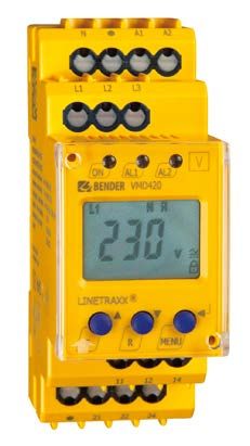
LINETRAXX® VMD420
Spannungs- und Frequenzrelais
zur Überwachung von 3(N)AC-Systemen mit 0…500 V auf Über- und Unterspannung sowie auf
Über- und Unterfrequenz
Voltage and frequency monitor
for monitoring of 3(N)AC systems up to 0…500 V for undervoltage, overvoltage, underfrequency,
overfrequency

VMD420_D00137_01_Q_DEEN/08.2021                                 Kurzanleitung / Quickstart DE/EN
LINETRAXX® VMD420

VMD420 Spannungs- und Frequenzrelais                             VME420 Voltage and frequency monitor

    i      Bestandteil der Gerätedokumentation
           sind neben dieser Kurzanleitung die
                                                                    i      Part of the device documentation in addi-
                                                                           tion to this quickstart is the enclosed
           „Sicherheitshinweise für Bender-Produkte“                       “Safety instructions for Bender products“
           und das dazugehörige Handbuch, herun-                           and the manual, downloadable at
           terladbar unter https://www.bender.de/                          https://www.bender.de/en/service-sup-
           service-support/downloadbereich.                                port/downloads.

Lieferumfang:                                                    Scope of delivery:
    •   VMD420                                                      •   VMD420
    •   Montageclip (1x)                                            •   Mounting clip (1x)
    •   Quick-Start DE/EN                                           •   Quick Start DE/EN
    •   Sicherheitshinweise                                         •   Safety instructions
Bestellangaben:                                                  Ordering information:

           Typ                 Nennspg. Un*/                   Versorgungsspg Us*/             Art.-Nr. /   Handbuch Nr. /
                             Nominal voltage Un*                Supply voltage Us*             Art.-No.      Manual No.
   VMD420-D-1
                            3(N)AC 0…500 V/ 288 V           AC 16…72 V/ DC 9,6 V…94 V        B73010005
 (Federklemmen /                                                                                               D00137
                                 15…460 Hz                       DC, 15…460 Hz              B73010005(W)
push-wire terminals)
                            3(N)AC 0…500 V/ 288 V           AC 16…72 V/ DC 9,6 V…94 V        B93010005
        VMD420-D-1                                                                                             D00137
                                 15…460 Hz                       DC, 15…460 Hz              B93010005(W)
   VMD420-D-2
                            3(N)AC 0…500 V/ 288 V                AC/DC 70…300 V
 (Federklemmen /                                                                              B73010006        D00137
                                 15…460 Hz                        DC, 15…460 Hz
push-wire terminals)
                             3(N)AC 0…500 V/ 288 V                   AC/DC 70…300 V
        VMD420-D-2                                                                              B93010006      D00137
                                    15…460 Hzz                        DC, 15…460 Hz
                   *Absolutwerte des Spannungsbereichs / * Absolute values of the voltage range
                   Montageclip für Schraubmontage (1 Stück je Gerät, Zubehör)
                                                                                                B98060008
                 Mounting clip for screw mounting (1 piece per device, accessories)

Bestimmungsgemäße Verwendung                                     Indended use
Das Spannungsrelais VMD420 überwacht                             The voltage monitor VMD420 monitors 3(N)AC
3(N)AC-Netze im Frequenzbereich 15…460 Hz                        systems in the frequency range 15…460 Hz for
auf Unter- und Überspannung sowie auf Unter-                     undervoltage, overvoltage, underfrequency
und Überfrequenz. Die Geräte eignen sich für                     and overfrequency. The devices are designed
den Nennspannungsbereich Un = 0…500 V. Das                       for the nominal voltage range Un = 0…500 V.
Gerät benötigt eine separate Versorgungs-                        Separate supply voltage Us is required.
spannung Us.
Eine andere oder darüber hinausgehende                           Any use other than that described in this ma-
Benutzung gilt als nicht bestimmungsgemäß.                       nual is regarded as improper.

2         VMD420_D00137_01_Q_DEEN/08.2021
LINETRAXX® VMD420
Abmessungen Dimensions
36
93 90 45 70,5
31,1
47,5
74,5
Montage Mounting
& 1x 2x Click
2.
! M4
100
107
1. 3. Click! M4
Variante A/Option A: Variante B/Option B:
Montage auf Hutschiene/DIN rail mounting Schraubbefestigung/Screw mounting
i Anwendung in Schienenfahrzeugen / DIN
EN 45545-2:2016! Beträgt der Abstand zu
i Application in railway vehicles/DIN EN
45545-2:2016! If the horizontal or vertical
benachbarten Komponenten, die nicht die distance to adjacent components which
Anforderung der Norm DIN EN 45545-2 do not meet the requirements in table 2 of
Tabelle 2 erfüllen, horizontal < 20 mm DIN EN 45545-2 is less than 20 mm or less
oder vertikal < 200 mm, sind diese als than 200 mm respectively, they are to be
gruppiert zu betrachten. regarded as grouped.
VMD420_D00137_01_Q_DEEN/08.2021 3LINETRAXX® VMD420
Anschluss Wiring
L1
L2 N A1 A2
L3
N
PE L1 L2 L3
ON AL1 AL2
L1 L2 L3 N
K1
US 11 12 14
T R MENU
K2
11 12 14
A1 A2 21 22 24 21 22 24
Klemme Anschlüsse Terminal Connections
A1, A2 Anschluss der Versorgungsspannung Us A1, A2 Connection of supply voltage Us
L1, L2, L3, (N) Anschluss an das zu überwachende System L1, L2, L3, (N) Connection to the system to be monitored
11, 12, 14 Alarm-Relais K1 11, 12, 14 Alarm relay K1
21, 22, 24 Alarm-Relais K2 21, 22, 24 Alarm relay K2
Inbetriebnahme Commissioning
Vor der Inbetriebnahme ist der ordnungsgemä- Prior to commissioning, check proper
ße Anschluss des Spannungsrelais zu überprü- connection of the voltage monitor.
fen.
1. Anlegen einer Spannung an den Mess- 1. Connecting a voltage to the measuring vol-
spannungseingang (L1, L2, L3, N). tage input (L1, L2, L3, N).
2. Anlegen der Versorgungsspannung an A1 2. Connecting the supply voltage to A1 and
und A2. A2.
3. Nach Anlegen der Messspannung und der 3. After connecting the measuring voltage and
Versorgungsspannung führt das VMD420 bei the supply voltage, the VME420 performs the
der ersten Inbetriebnahme die Preset- preset function at the first start-up, see follo-
Funktion aus, siehe nachfolgende wing description.
Beschreibung.
4 VMD420_D00137_01_Q_DEEN/08.2021LINETRAXX® VMD420
Preset-Funktion/Werkseinstellung Preset function/factory setting
Bei erster Inbetriebnahme stellen sich in During the first start-up process the following
Abhängigkeit von Un automatisch vordefinierte response values are automatically set related to
Ansprechwerte ein: Un:
Ansprechwert Überspannung (> U) 1,1 Un Response value overvoltage (> U) 1.1 Un
Ansprechwert Unterspannung (< U) 0,85 Un Response value undervoltage (< U) 0.85 Un
Hysterese U 5% Hysteresis U 5%
Unterfrequenz < Hz fn - 1 Hz, OFF Underfrequency < Hz fn - 1 Hz, OFF
Überfrequenz > Hz fn + 1 Hz, OFF Overfrequency > Hz fn + 1 Hz, OFF
Hysterese Frequenz (Hys Hz) 0,2 Hz Hysteresis frequency (Hys Hz) 0.2 Hz
Frequenzalarm (< U Hz) on Frequency alarm (< U Hz) on
Fehlerspeicher (M) on Fault memory (M) on
Arbeitsweise K1 (> U, Asy) Arbeitsstrom-Betrieb (n.o.) Operating principle K1 (> U, Asy) N/O operation-(n.o.)
Arbeitsweise K2 (< U, Asy) Ruhestrom-Betrieb (n.c.) Operating principle K2 (< U, Asy) N/C operation (n.c.)
AL1/AL2 signalisieren Alarmzustand AL1/AL2 indicate the alarm state of
von K1/K2 (LEd) OFF K1/K2 (LEd) OFF
Alarm bei Gerätestart an Alarm to K1/K2 (S.AL) when the
K1/K2 (S.AL) OFF device is started OFF
Anlaufverzögerung (t) t=0s Start-up delay t=0s
Asymmetrie (Asy) 30 % Asymmetry (Asy) 30 %
Phasenfolge-Überwachung OFF Phase sequence monitoring OFF
Ansprechverzögerung ton1 = 0 s Response delay ton1 = 0 s
ton2 = 0 s ton2 = 0 s
Rückfallverzögerung toff = 0,5 s Delay on release toff = 0.5 s
Messmethode 3Ph Method of measurement 3Ph (phase-to-phase
(Außenleiter-Messung) voltage measurement)
Passwort 0, OFF Password 0, OFF
Für den Fall, dass die gemessene Spannung au- If the measured voltage is not within the preset
ßerhalb des in der Tabelle definierten Preset- operating range listed in the table, the message
Arbeitsbereichs liegt, erscheint im Display die "AL not Set“ appears on the display. Therefore it
Meldung „AL not Set“. Somit ist es erforderlich, is necessary to set the response values for Alarm
die Ansprechwerte für Alarm 1 (AL1) und Alarm 1 (AL1) and Alarm 2 (AL2) manually.
2 (AL2) manuell einzustellen. Der Ablauf ist de- A detailed description of the process is given in
tailliert im Abschnitt „Einstellen der Parameter“ the chapter "parameter setting“.
beschrieben.
After restoring the factory settings, the preset
Die Preset-Funktion wird nach Rücksetzen auf function is automatically active again.
die Werkseinstellungen erneut ausgeführt.
During operation, the preset function can be
Während des Betriebs können Sie über das started manually via the menu SEt.
Menü SEt die Preset-Funktion manuell starten.
VMD420_D00137_01_Q_DEEN/08.2021 5LINETRAXX® VMD420
Eigene Einstellungen (Übersicht) User settings (overview)
Menu Parameter FAC¹ Eigene Einstellungen/ Einstellbereich/ AL-LED
User setting Setting range
U ON PRESET V 500 V 1*
U Hys 5% % 1 %. . . 40 %
Asy % 5 %. . . 30 % 1+2*
AL < Hz OFF PRESET Hz 10 Hz 1+2*
> Hz OFF PRESET Hz 500 Hz 1+2*
HZ Hys 0.2 Hz Hz 0,1 Hz . . . 2,0 Hz
< U_Hz ON ON / OFF
PHS OFF R R/L 1+2*
M ON ON / OFF / CON
1 n.o.
2 n.c.
LEd OFF 1/2 **
1 Err OFF
r1 < U OFF
r1 > U ON
r1 Asy ON
r1
r1 Hz< ON
r1 Hz> ON
out
1 PHS ON
1 S.AL OFF ***
2 Err OFF
r2 U< ON
r2 U> OFF
r2 Asy ON
r2
r2 Hz< ON
r2 Hz> ON
2 PHS ON
2 S.AL OFF ***
6 VMD420_D00137_01_Q_DEEN/08.2021LINETRAXX® VMD420
Menu Parameter FAC1 Eigene Einstellungen/ Einstellbereich/ AL-LED
User setting Setting range
ton 1 s
ton 2 0s s 0 s. . . 300 s
t
t s
toff 0.5 s s 0 s. . . 300 s
L1, L2, L3 3Ph 3Ph/3 n
OFF 0
Set FAC
PrE 3Ph 3Ph/3 n
SYS
InF
HiS Clr
1 Werkseinstellungen/factory settings
* nur bei LEd = off, ** nur bei LEd = on, *** je nach Einstellung LEd
* only when LEd = off, ** only when LEd = on, *** depending on LEd setting
Technische Daten Technical data
Tabellarische Daten Data in tabular form
Isolationskoordination nach IEC 60664-1/IEC 60664-3 Insulation coordination acc. to IEC 60664-1/IEC 60664-3
Bemessungsspannung.........................................................400 V Rated insulation voltage .................................................... 400 V
Bemessungs-Stoßspannung/Verschmutzungsgrad.........4 kV / III Rated impulse voltage/Pollution degree........................ 4 kV / III
Sichere Trennung (verstärkte Isolierung) zwischen:..................... Protective separation (reinforced insulation) between:................
......................(A1, A2) - (N, L1, L2, L3) - (11-12-14) - (21-22-24) ......................(A1, A2) - (N, L1, L2, L3) - (11-12-14) - (21-22-24)
Spannungsprüfung nach IEC 61010-1: Voltage test acc. to IEC 61010-1:
(N, L1, L2, L3) - (A1, A2), (11, 12, 14).............................. 3,32 kV (N, L1, L2, L3) - (A1, A2), (11, 12, 14) ............................. 3.32 kV
(N, L1, L2, L3) - (21, 22, 24)............................................ . 2,21 kV (N, L1, L2, L3) - (21, 22, 24) ............................................. 2.21 kV
(A1, A2) - (11, 12, 14) - (21, 22, 24) ................................ 2,21 kV (A1, A2) - (11, 12, 14) - (21, 22, 24) ................................ 2.21 kV
Versorgungsspannung Supply voltage
VMD420-D-1: VME420-D-1:
Versorgungsspannung Us .............. AC 16…72 V / DC 9,6…94 V Supply voltage Us .......................... AC 16…72 V / DC 9.6…94 V
Frequenzbereich Us .................................................15…460 Hz Frequency range Us ..................................................15…460 Hz
VMD420-D-2: VME420-D-2:
Versorgungsspannung Us ............................... AC/DC 70…300 V Supply voltage Us ........................................... AC/DC 70…300 V
Frequenzbereich Us .................................................15…460 Hz Frequency range Us ..................................................15…460 Hz
Eigenverbrauch ................................................................ ≤ 4 VA Power consumption ..........................................................≤ 4 VA
Messkreis Measuring circuit
Messbereich (Effektivwert) (L-N)..................... AC / DC 0…288 V Measuring range (r.m.s.) (L-N)....................... AC / DC 0…288 V
Messbereich (Effektivwert) (L-L)...................... AC / DC 0…500 V Measuring range (r.m.s.) (L-L)........................ AC / DC 0…500 V
Bemessungsfrequenz fn ........................................DC, 15..460 Hz Rated frequency fn .............................................DC, 15…460 Hz
Frequenzanzeige ......................................................10…500 Hz Frequency range ......................................................10…500 Hz
VMD420_D00137_01_Q_DEEN/08.2021 7Schaltglieder Switching elements
Anzahl ......................................................2 x 1 Wechsler (K1, K2) Number of changeover contacts ............................ 2 x 1 (K1, K2)
Arbeitsweise............................ Ruhestrom n.c./Arbeitsstrom n.o. Operating principle ........................N/C operation/N/O operation
K2: Err, < U, > U, Asy, < Hz, > Hz, PHS, S.AL K2: Err, < U, > U, Asy, < Hz, > Hz, PHS, S.AL
(Unterspannung < U, Asymmetrie Asy, Ruhestrom n.c.)* (undervoltage < U, asymmetry Asy, N/C operation n.c.)*
K1: Err, < U, > U, Asy, < Hz, > Hz, PHS, S.AL K1: Err, < U, > U, Asy, < Hz, > Hz, PHS, S.AL
(Überspannung >U, Asymmetrie Asy, Arbeitsstrom n.o)* (overvoltage >U, asymmetry Asy, N/O operation no.)*
Elektrische Lebensdauer bei Bemessungsbedingungen ............... Electrical endurance..........................10000 switching operations
VMD420_D00137_01_Q_DEEN/08.2021/ pdf / © Bender GmbH & Co. KG, Germany – Subject to change! The specified standards take into account the edition valid until 08/2021 unless otherwise indicated.
....................................................................... 10000 Schaltspiele
Kontaktdaten nach IEC 60947-5-1: Contact data acc. to IEC 60947-5-1:
Gebrauchskategorie ..................................................................... Utilisation category ......................................................................
..............................AC 13..... AC 14 ..... DC-12 .... DC-12..... DC-12 ............................. AC 13..... AC 14 ..... DC-12 .... DC-12..... DC-12
Bemessungsbetriebsspannung .................................................... Rated operational voltage ...........................................................
..............................230 V..... 230 V ........ 24 V ..... 110 V..... 220 V ..............................230 V..... 230 V ........ 24 V ..... 110 V..... 220 V
Bemessungsbetriebsstrom ........................................................... Rated operational current.............................................................
.................................5 A......... 3 A .......... 1 A ...... 0,2 A...... 0,1 A .................................5 A......... 3 A .......... 1 A ...... 0.2 A...... 0.1 A
Minimale Kontaktbelastung (Referenzangabe des Herstellers).... Minimum contact load (relay manufacturer's reference) .............
................................................................ 1 mA bei AC/DC ≥ 10 V ..................................................................1 mA at AC/DC ≥ 10 V
( )* = Werkseinstellung ( )* = factory setting
Normen Standards
Das VMD420 entspricht den Anforderungen der The VMD420 complies with the requirements of
Norm DIN EN 45545-2. DIN EN 45545-2.
Alle Rechte vorbehalten. All rights reserved.
Nachdruck und Vervielfältigung Reprinting and duplicating
nur mit Genehmigung des Herausgebers. only with permission of the publisher.
Bender GmbH & Co. KG Bender GmbH & Co. KG
Postfach 1161 • 35301 Grünberg • Deutschland PO Box 1161 • 35301 Grünberg • Germany
Londorfer Str. 65 • 35305 Grünberg • Deutschland Londorfer Str. 65 • 35305 Grünberg • Germany
Tel.: +49 6401 807-0 • Fax: +49 6401 807-259 Tel.: +49 6401 807-0 • Fax: +49 6401 807-259
E-Mail: info@bender.de • www.bender.de E-Mail: info@bender.de • www.bender.deSie können auch lesen