Development of a Concreting System Based on the Climbing Formwork Concept for the Partial Filling of the Friedlicher Nachbar Shaft - ZPP ...
←
→
Transkription von Seiteninhalten
Wenn Ihr Browser die Seite nicht korrekt rendert, bitte, lesen Sie den Inhalt der Seite unten

Carsten Linka
Dieter Hardes
TOPICS
Development of a Concreting System Based on the
Climbing Formwork Concept for the Partial Filling
of the Friedlicher Nachbar Shaft
The Friedlicher Nachbar shaft in Bochum is one of the 13 central ing a climbing formwork system. While this technique has prov-
water pumping stations operated by RAG Aktiengesellschaft, en itself many times over in the structural engineering sector it
Essen/Germany. One of the unusual features of this installation has never previously been used in the mining industry. The spe-
is that the operation to convert to a well-type system has to be cifics of adapting to the special characteristics of a mine shaft
carried out without switching off the pumps in the auxiliary ven- environment were agreed at the planning stage between the
tilation shaft as any such shutdown would result in an increase in formwork manufacturers, the concrete suppliers, the technical
the mine water levels. This would lead to a transfer of water into experts involved and the Arnsberg District Government. A full-
the adjoining water management zones, something that must scale concreting trial then confirmed the suitability of the form-
be avoided at all costs. work system, the specially developed concrete formula and the
Because of ongoing pumping operations the conventional meth- supporting stage construction. Various measurement systems
od of partial backfilling using the casing pipe method could be were used to investigate the development of hydration heat
used. What is more, the significant lack of vertical alignment in in the concrete, the pressure build-up acting on the formwork
the shaft also ruled out the casing pipe system. This meant hav- system, the degree of adhesion to the shaft wall, the concrete
ing to investigate the use of alternative technologies, a process distribution during the pour and the strength development of
that ultimately led to the concept of constructing a well pipe us- the concrete.
Entwicklung eines Betoniersystems nach dem
Funktionsprinzip der Kletterschalung zur
Teilverfüllung des Schachts Friedlicher Nachbar
Der Schacht Friedlicher Nachbar in Bochum gehört zu den 13 zen- Brunnenröhre durch den Einsatz einer Kletterschalung. Dieses
tralen Wasserhaltungsstandorten der RAG Aktiengesellschaft, Verfahren hat sich zwar im Hochbau tausendfach bewährt, ist
Essen. Die Besonderheit an diesem Standort ist, dass der Umbau aber im Bergbau bislang nie eingesetzt worden. Die Anpassung
zum Brunnenbetrieb ohne Abschaltung der Pumpen im sonder- an die Besonderheiten im Schacht wurde im Zuge der Planung
bewetterten Schacht erfolgen muss, da das Abschalten ein An- zwischen dem Hersteller des Schalungssystems, den Betonliefe-
stieg des Grubenwassers zur Folge hätte. Hieraus würden Was- ranten, den beteiligten Sachverständigen und der Bezirksregie-
serübertritte in die benachbarten Wasserprovinzen resultieren, rung Arnsberg abgestimmt. Ein Betonierversuch im Maßstab 1:1
die unter allen Umständen vermieden werden müssen. lieferte den Nachweis der Eignung des Schalungssystems, der
Die übliche Vorgehensweise der Teilverfüllung mit Hüllrohrtech- entwickelten Betonrezeptur und der tragenden Bühnenkon
nik kann aufgrund des laufenden Pumpbetriebs nicht verwendet struktion. Dabei wurden über diverse Messsysteme die Hydrata-
werden. Überdies wurde die Verwendung von Hüllrohren durch tionswärmeentwicklung des Betons, die Druckentwicklung auf
die enorme Schiefstellung des Schachts unmöglich. Die Ent- das Schalungssystem, das Haftungsverhalten auf die Schacht-
wicklung alternativer Technologien musste untersucht werden wand, die Verteilung des Betons bei der Verfüllung und die Fes-
und führte schlussendlich zum Konzept der Herstellung einer tigkeitsentwicklung des Betons untersucht.
Mining Report Glückauf 156 (2020) No. 2 125
1 Einleitung
Da die übliche Vorgehensweise mit Hüllrohrtechnik beim Umbau
zum Brunnenbetrieb am Bochumer Schachtstandort Friedlicher
Nachbar Schacht 2 der RAG Aktiengesellschaft, Essen, nicht an-
gewendet werden kann, weil der Pumpbetrieb aufrechterhalten
bleiben muss, kommt die alternative Herstellung einer Brunnen-
röhre durch eine Kletterschalung zum Einsatz (1).
Dieses Konzept basiert auf einer aus dem Hochbau üblichen
Schaltechnik, die für den Einsatz im Schacht modifiziert werden
musste. In enger Zusammenarbeit mit Sachverständigen ent-
schied man, diese neu entwickelte Technik vor dem ersten Einsatz
im Schacht in einem Großversuch zu erproben.
2 Örtliche und technische Rahmenbedingungen
Der Schacht hat eine Teufe von 809 m und einen Durchmesser
von 4,5 m. Folgende Einbauten sind vorhanden (Bild 1):
• Nördlich der Mittelachse (Ost-West-Richtung): drei frei-
hängend verlagerte ZSM-Steigleitungen (ZSM – zugfeste
Steckmuffe) DN 300 mit angehängten Tauchmotorpumpen
(d = 660 mm).
• Südlicher Schachtbereich: an Einstrichen verlagerter Fahrschacht.
• Südöstlicher Stoß: Lutte DN 600.
• Nördlicher Schachtbereich: in Ost-West-Richtung verlaufender
Einstrich; Fallwasserleitung DN 100; Druckluftleitung DN 50.
• Drallschellenbühne bei 220,5 m Teufe.
• Revisionsbühne bei 3,0 m Teufe.
Fig. 1. Shaft cross section and profile view.
Bild 1. Schachtschnitt- und -scheibe. Source/Quelle: RAG Zur Beurteilung der Schachtschiefstellung wurde im Rahmen
der Umbauplanung im April 2014 durch die DMT GmbH & Co. KG
eine Schieflagemessung mittels Laserscanner durchgeführt (Bil-
1 Introduction der 2, 3). Im Ergebnis wurde eine Schachtschiefstellung von 0,9 m
In view of the fact that the conventional casing pipe method can- in Nord-Süd- und 0,3 m in West-Ost-Richtung ermittelt. Dies hat
not be employed for converting to a well-type operating regime einen erheblichen Einfluss auf die mögliche Pumpenanordnung.
at the RAG-operated Friedlicher Nachbar shaft 2 in Bochum/ Die Messung konnte nur bis 221,6 m Teufe durchgeführt
Germany, this being due to the need to maintain pumping op- werden, da für tiefere Messungen zunächst Einbauten geraubt
erations, it was subsequently decided that a climbing formwork werden müssen bzw. der Wasserspiegel abgesenkt werden muss.
system could be used as an effective alternative (1). Die vorliegende Messung ist jedoch voraussichtlich für die weite-
The concept that was to be applied, which is based on the re Planung der Pumpenanordnung zunächst völlig ausreichend.
formwork construction technique that is standard practice in the Eine gravierende Erhöhung der Schachtschiefstellung zur Teufe
field of structural engineering, had to be modified for use in a ist nicht zu erwarten.
mining shaft environment. Working closely with specialists in the Der Korb, der im Schacht Friedlicher Nachbar vorhandenen
field it was decided that the newly developed technology should Befahrungsanlage ist am östlichen und westlichen Stoß durch
be tested in a large-scale trial before it was finally used in a real Spurlatten geführt. Diese sind an Konsolen verlagert. Der eineta-
shaft environment. gige Förderkorb hat eine Nutzlast von 0,44 t und fährt mit einer
maximalen Geschwindigkeit von 0,3 m/s.
2 Local conditions and technical features
The shaft in question is 809 m in depth and has a diameter of 4.5 m. 3 Pumpenanordnung
The following fittings and installations are present (Figure 1): Für die Planung möglicher Anordnungen der Tauchmotorpum-
• North of the central axis (running east to west): three freely pen ist die Schachtschiefstellung das entscheidende Kriterium.
suspended DN 300 strain-resistant socket-type riser pipes Deshalb wurde das Ingenieurbüro ZPP Ingenieure AG, Bochum,
with submersible pumps attached (d = 660 mm). mit einer Machbarkeitsstudie beauftragt, die auch die Einsatz-
• Southern shaft zone: ladder shaft mounted on buntons. möglichkeit einer Kletterschalung untersuchen sollte. In Bild 4 ist
• South-east wall: DN 600 ducting. die Ist-Situation (1.) unter Einbeziehung der Schachtschiefstellung
• Northern shaft zone: bunton system running east to west; dargestellt. Die beiden weiteren Darstellungen (2. und 3.) zeigen
DN 100 water fall pipe; DN 50 compressed-air pipe. die möglichen Varianten der Pumpenanordnung. Der Schacht-
• Twist-resistant scaffold at 220.5 m level. querschnitt ist dabei idealisiert abgebildet (schwarz: Niveau
• Inspection scaffold at the 3.0 m level. Rasenhängebank (RHB), rot: Niveau Widerlager).
126 Mining Report Glückauf 156 (2020) No. 2
As part of the conversion planning work the DMT
GmbH & Co. KG, carried out tilt measurements by

                                                                                                                                                  TOPICS
laser scanner in April 2014 in order to assess the ver-
tical misalignment (Figures 2, 3). These found that
the shaft exhibited a misalignment of 0.9 m running
north to south and of 0.3 m running west to east.
This would have a massive influence on the possible
pump configuration.
     These measurements could only be taken to a
depth of 221.6 m as any work below this level would
first have required the removal of the shaft fittings
and possibly the lowering of the water level. However
the measurements that were possible were consid-
ered as perfectly adequate for any subsequent plan-
ning of the pump configuration. The degree of mis-
alignment was not expected to increase dramatically
further down the shaft column.
     The cage fitted to the existing inspection system
in the Friedlicher Nachbar shaft runs on shaft guides
attached to the east and west side wall. These guides
are mounted on a series of brackets. The single-deck
cage has a payload capacity of 0.44 t and travels at a
maximum speed of 0.3 m/s.

3      Pump configuration
The tilt of the shaft was the decisive factor when it
came to planning possible layouts for the submers-
ible pumps. For this reason Bochum-based consult-
ing engineers ZPP Ingenieure AG, Bochum/Germany,
were commissioned to carry out a feasibility study
that was also to examine the possible application of
a climbing formwork system. The existing situation
in the shaft (1.) is shown in Figure 4 in conjunction
with the shaft tilt. The other two depictions (2 and          Fig. 2, 3. Results of the DMT laser scan.
                                                              Bilder 2, 3. Laserscan der DMT. Source/Quelle: DMT
3.) show the possible variants for the pump layout.
Here the shaft cross section has been presented in an
idealised form (black profile: pit-bank level, red profile: abutment
level).                                                                       3.1 Anordnung der Tauchpumpen in Reihe
                                                                              Eine bessere Möglichkeit eine Anordnung der Pumpen in Reihe
3.1 Arranging the submersible pumps in line                                   herzustellen, ergibt sich durch eine Verschiebung der Pumpenrei-
A better option for arranging the pumps in line is to move the                he um 0,75 m nach Süden bei gleichzeitigem Verschwenken der
row 0.75 m to the south and at the same time pivot it by 15°. This            Reihe um 15°. Dadurch würden minimale Abstände von 0,45 m zu
would create a minimum distance of 0.45 m to the shaft walls.                 den Schachtstößen entstehen.

                                                                               3.2  Anordnung der Tauchpumpen im Dreieck
                                                                               Eine weitere Möglichkeit besteht darin, die Tauchpumpen
                                                                               im Dreieck anzuordnen. Für die Planung wurde an dieser
                                                                               Stelle ein Abstand der Tauchpumpenkörper untereinander
                                                                               von 0,3 m festgelegt. Dies entspricht dem im Istzustand
                                                                               vorhandenen Abstand.
                                                                                   Um unter Berücksichtigung der Schachtschiefstellung
                                                                               die maximalen Schachtabstände zu generieren, ist eine
                                                                               Verschiebung des Zentrums des Dreiecks um 0,55 m nach
                                                                               Süden erforderlich. Dadurch entstehen Abstände von mini-
                                                                               mal 0,7 m zwischen Tauchmotorpumpe und Schachtwand.
                                                                                   Die Anordnung der Tauchpumpen im Dreieck stellt so-
    Fig. 4. Pump configuration (1). // Bild 4. Pumpenanordnung (1).
                                                                               mit die optimale Lösung dar.

                                                                                                  Mining Report Glückauf 156 (2020) No. 2   127
Fig. 5. Variant 1 – pump pipes                  Fig. 6. Variant 2 – pump pipe constructed
    constructed using split casing pipes.           using split-type lost formwork.              Fig. 7. Variant 3 – pump pipe constructed using
    Bild 5. Variante 1 – Herstellung der            Bild 6. Variante 2 – Herstellung einer       climbing formwork.
    Pumpenröhren mit Einsatz geteilter              Pumpenröhre mit Einsatz einer geteilten      Bild 7. Variante 3 – Herstellung einer Pumpenröhre mit
    Hüllrohre. Source/Quelle: RAG                   verlorenen Schalung. Source/Quelle: RAG      Einsatz einer Kletterschalung. Source/Quelle: RAG

3.2 Arranging the pumps in a triangle                                               4    Herstellverfahren
Another possibility is to arrange the pumps in a triangle. This                     Grundsätzlich ist zwischen einem Betrieb der Pumpen in einer
would involve placing them each 0.3 m apart. This corresponds to                    gemeinsamen Pumpenröhre und einem Betrieb in getrennten
the gaps left between the pump units in the current situation.                      Röhren zu unterscheiden. Die Herstellverfahren müssen einen
In order to create the maximum distance settings to the shaft                       unterbrechungsfreien Pumpbetrieb gewährleisten.
wall, while at the same time taking account of the tilt, it is neces-
sary to shift the centre of the triangle 0.55 m to the south. This                  Als Herstellverfahren kommen in Frage:
produces a spacing of at least 0.7 m between each submersible                       1. Herstellung der Pumpenröhren mit Einsatz geteilter Hüllrohre.
pump and the shaft wall.                                                            2. Herstellung einer Pumpenröhre mit Einsatz einer geteilten
    Placing the pumps in a triangular arrangement therefore rep-                       verlorenen Schalung.
resents the optimum solution.                                                       3. Herstellung einer Pumpenröhre mit Einsatz einer Kletterscha-
                                                                                       lung.
4      Fabrication method
The basic choice is between operating the pumps in a common pump                    Das erste Herstellverfahren erfordert den Einsatz von in Längs-
pipe and operating them in separate pipes. Here the method of fabri-                richtung geteilten Hüllrohren (Bild 5). Der Einsatz dieser Rohre
cation must ensure an uninterrupted operation of the pumps.                         verursacht einen sehr hohen Transport- und Montageaufwand
                                                                                    je Betonierabschnitt. Aufgrund der aufwändigen Fertigung der in
The following options are possible:                                                 Längsrichtung geteilten Hüllrohre entstehen darüber hinaus bei
1. Pump pipes fabricated using split casing pipes.                                  dieser Variante die höchsten Materialkosten je Meter.
2. Pump pipe fabricated using split-type lost formwork.                                 Als zweites Herstellverfahren bietet sich der Einsatz einer in
3. Pump pipe fabricated using climbing formwork.                                    Längsrichtung geteilten, verlorenen Schalung an (Bild 6). Durch
                                                                                    die Verwendung einer großen Röhre anstelle von drei kleinen
The first method requires the use of casing pipes that are split                    Röhren wird die Anzahl der Schraubverbindungen verringert.
lengthwise (Figure 5). Using pipes of this type results in very high                Auch dieses Herstellverfahren verursacht einen hohen Transport-
transport and assembly costs for each casting section. Because                      und Montageaufwand je Betonierabschnitt. Dieser ist jedoch ge-
of the expensive production cost associated with these casing                       ringer als beim Einsatz von geteilten Hüllrohren. Gleiches trifft
pipes, which are split lengthwise, this design also generates the                   auch auf die Materialkosten zu.
highest material costs per metre.                                                       Als drittes Herstellverfahren wurde der Einsatz einer Kletter-
    The second method of construction involves the use of a lost                    schalung untersucht (Bild 7). Die Kletterschalung zeichnet sich
formwork system that is split lengthwise (Figure 6). Using one                      durch wiederkehrende Einsatzmöglichkeit und eine reduzierte
large pipe in place of three smaller ones reduces the number of                     Montagezeit aus. Die nach dem Ausschalen des Betons erstellte
bolted connections. This method of fabrication also means high                      Vorbausäule stellt höhere Anforderungen an den verwendeten
transport and assembly costs per casting section. However, these                    Beton (2). Hierbei stehen verhältnismäßig geringe Kosten für die
are lower than in the case of split casing pipes. The same also ap-                 Schalung und ein einmaliger, geringer Montageaufwand erhöh-
plies to the material costs.                                                        ten Materialkosten für den eingesetzten Beton gegenüber.

128       Mining Report Glückauf 156 (2020) No. 2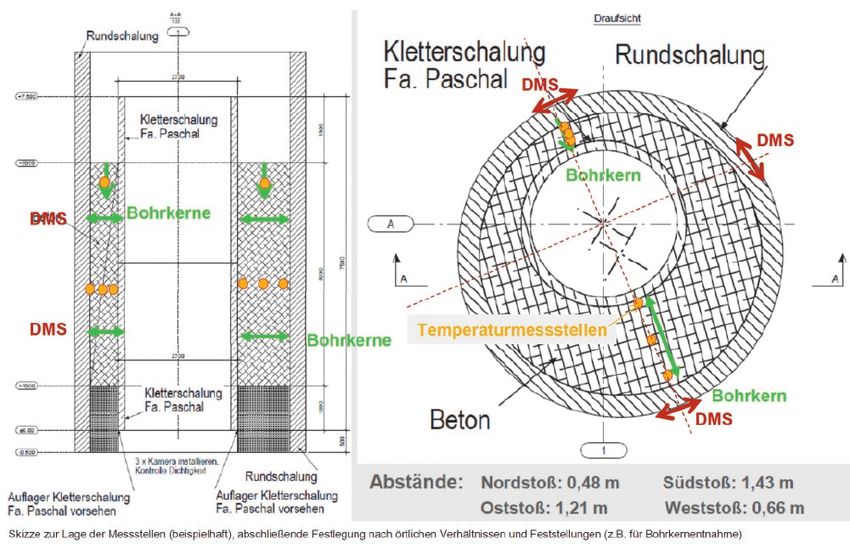
The third construction method to be investigated was the                Alle drei Herstellverfahren wurden auf der Grundlage der spe-
climbing formwork system (Figure 7). This structure offers the ad-      zifischen Kosten, die das einzelne System verursacht, analysiert

                                                                                                                                                TOPICS
vantages of repetitive application and a reduced assembly time.         und bewertet. Dazu wurden für jedes Verfahren die Materialkos-
The shaft liner that is produced when the formwork is stripped          ten auf der Basis von Informationsangeboten ermittelt. Gleiches
away places higher demands on the concrete material (2). With           erfolgte für den jeweils einzusetzenden Verfüllbaustoff (höhere
this method the relatively low cost of the formwork and the non-        Ansprüche an die Betonqualität bei Einsatz einer Kletterscha-
recurring and reduced cost of the assembly work are offset by the       lung). Der Transport- und Montageaufwand wurde anhand vor-
increased cost of the concrete materials.                               liegender Erfahrungswerte abgeschätzt.
     All three construction processes were analysed and assessed
on the basis of the specific costs generated by each individual         5   Auswahl des Verfahrens
system. The material costs for each of the three processes were         Aufgrund des ermittelten Einsparpotentials wurde die Herstel-
determined with reference to a wide range of information. Simi-         lung eines gemeinsamen Pumpenschachts für die drei Tauchmo-
lar calculations were carried out for the filler material (the climb-   torpumpen unter Einsatz einer Kletterschalung beschlossen. Die-
ing formwork system places greater demands on the quality of            ses Verfahren ist im Hochbau tausendfach bewährt, wurde aber
the concrete). The transport and assembly costs were estimated          im deutschen Steinkohlenbergbau noch nie eingesetzt. Daher
using the available empirical data.                                     wurde im Vorfeld in einer gutachterlichen Stellungnahme durch
                                                                        das Ingenieurbüro LPI Ingenieurgesellschaft mbH, Hannover, die
5   Selection process                                                   Dauerhaftigkeit von Betonbauwerken beim Einsatz einer Kletter-
In view of the cost saving potential involved it was decided that       schalung bestätigt (3).
the best option was to construct a common pump shaft for the
three submersible pumps using a climbing formwork system.               6   Aufbau und Funktionsweise des Betoniersystems
This technique has proven itself many times over in the struc-              Kletterschalung
tural engineering sector, though has never been employed in             Für den Einsatz im Schacht 2 Friedlicher Nachbar wurde ein paten-
the German coal mining industry. Before the work commenced,             tiertes System der Firma PASCHAL-Werk G. Maier GmbH, Gifhorn,
therefore, the Hanover-based firm of consulting engineers LPI           modifiziert. Die Anpassung an die Besonderheiten im Schacht
was commissioned to present an expert opinion that confirmed            wurde im Zuge der Detailplanung in intensiven Gesprächen mit
the durability and stability of concrete structures built using the     dem Schalungshersteller PASCHAL-Werk, den beteiligten Sach-
climbing formwork method (3).                                           verständigen der DMT und ZPP abgestimmt (Bilder 8, 9).
                                                                            Die Betoniereinheit besteht aus der Schalung (3 x 3 Ringseg-
6   Design and operating principle of the climbing                      mente, verbunden durch Ausschalkeile) mit Streben zum Aus-
    formwork concreting system                                          richten der Schalung und der Klettereinheit (hier Ausführung als
A formwork system patented by the company PASCHAL-Werk                  ortsveränderliche Bühne nach TAS) mit Betonierbühne mit Kopf-
G. Maier GmbH, Gifhorn/Germany, was modified for use in Friedli-        schutzbühne, Revisions-, Kletter- und Nachlaufbühne sowie Fahr-
cher Nachbar shaft 2. The modifications needed to adapt this sys-       ten zur Verbindung der einzelnen Bühnenebenen.
tem to the specific characteristics of the mine shaft were agreed           Die Schalung besteht aus drei Kreisringen, die in jeweils drei
during a detailed planning process that involved intensive discus-      Segmente unterteilt sind. Die beiden oberen Kreisringe haben eine
sions with the formwork manufacturers PASCHAL, the team of              Höhe von 3.000 mm, der untere Ring hat eine Höhe von 1.500 mm.
specialists from DMT and engineers from ZPP (Figures 8, 9).             Der Durchmesser der oberen Ringe beträgt 2.700 mm, der unte-
    The concreting unit is made up of the formwork casing (3 x 3        re Ring ist 5 mm kleiner im Durchmesser. Im unteren Ring ist in
ring segments connected by striker wedges) with struts for align-       1.000 mm Höhe eine aufblasbare Dichtung integriert. Diese Dich-
ing the formwork and the climbing unit (in this case designed as        tung verhindert zuverlässig ein Durchsickern von Betonemulsion
a mobile platform scaffold to TAS specifications) with its concret-     in die bereits fertiggestellte Betonröhre. Der kleinere Durchmesser
ing platform with overhead deck, inspection scaffold, climbing          ermöglicht eine geringe Abweichung der Schalungsachse von der
deck and trailing scaffold, along with ladderways connecting the        Lotrechten zwecks ggf. erforderlicher Richtungskorrektur.
individual platform levels.                                                 Die Klettereinheit besteht aus einer ortsveränderlichen, auf-
    The formwork comprises three circular rings each divided into       gehängten Bühne nach TAS. Die einzelnen Bühnenebenen beste-
three segments. The two upper rings are 3,000 mm in height,             hen aus einer sternförmigen Trägerkonstruktion. Sie sind durch
while the bottom ring is 1,500 mm in height. The upper rings are        Hängestreben miteinander verbunden. Die oberste Bühnenebe-
2,700 mm in diameter and the bottom ring has a diameter that is         ne ist die sogenannte Betonierbühne. Von hier aus erfolgt das
5 mm smaller. The bottom ring incorporates an inflatable seal at        Verspannen und Entspannen der Schalung. Auch die Bedienung
a height of 1,000 mm. This seal effectively prevents any seepage        der zum Ausrichten der Schalung angeordneten Streben erfolgt
of the concrete emulsion into the newly constructed concrete            von der Betonierbühne aus. Die Trägerkonstruktion dieser Büh-
pipe. The ring's smaller diameter allows the formwork axis to be        nenebene beinhaltet auch die Aufhängekonstruktion für die ge-
deviated slightly from the vertical in the event that directional       samte Bühne. Weiterhin ist auf dieser Bühne eine Aufständerung
changes or corrections have to be made.                                 für die Kopfschutzbühne angeordnet.
    The climbing unit is composed of a mobile suspended scaf-               Zur Teufe hin folgt eine Revisionsbühne. Von dieser Bühne
fold that is designed to TAS specifications. The individual platform    kann die Funktion der Verspanneinrichtung überwacht werden.

                                                                                                Mining Report Glückauf 156 (2020) No. 2   129
Fig. 8. Layout drawing of the climbing formwork concreting system.
    Bild 8. Systemskizze des Betoniersystems Kletterschalung.                 Fig. 9. Operating principle of the climbing formwork system.
    Source/Quelle: RAG                                                        Bild 9. Funktionsweise der Kletterschalung. Source/Quelle: RAG

levels feature a star-shaped supporting structure and are con-            Es folgt die Kletterbühne. Darauf ist die Schalung aufgesetzt. Die
nected together by hanging struts. The topmost platform level is          Bedienung der aufblasbaren Dichtung erfolgt von hier. Letzte
referred-to as the pouring platform. It is from this level that the       Bühnenebene ist die Nachlaufbühne. Von dieser Ebene kann der
formwork is tightened up and slackened off. The struts that serve         Zustand des letzten Betonierabschnitts kontrolliert werden. Ggf.
to align the formwork are also operated from the pouring plat-            erforderliche Nachbehandlungsmaßnahmen können ebenfalls
form. The supporting structure for this platform level addition-          von dieser Bühne ausgeführt werden.
ally contains the suspension assembly for the entire platform. A
mounting system for the overhead deck is also located on this             7      Entwicklung einer geeigneten Betonrezeptur
platform level.                                                           Um den Anforderungen der Kletterschalung an die Betontechnik
    Further down comes the inspection scaffold, which can be              Rechnung zu tragen, wurde im Auftrag der RAG von der LPI eine
used to monitor the operation of the tensioning system. This is           spezielle Betonrezeptur entwickelt.
followed by the climbing deck on which the formwork system                     Vorgabe war hierbei einerseits die Einhaltung der Versatz-
rests. The inflatable seal is operated from this level. The final plat-   verordnung (VersatzV, 2002) (4), zum anderen sollten nur Mate-
form level is the trailing scaffold and the condition of the last         rialien verwendet werden, die im Einzugsgebiet des Ruhrgebiets
casting section can be controlled from this level. Any aftercare          verfügbar sind. Weiterhin mussten die Anforderungen aus der
measures that may prove necessary can also be carried out from            Standsicherheitsberechnung (2) für die Schachtverfüllung be-
this bottom scaffold.                                                     rücksichtigt werden. Der Beton der Vorbauschale muss ein gerin-
                                                                          ges Schwindmaß aufweisen und eine schnelle Eigentragfähigkeit
7      Development of a suitable concrete formula                         entwickeln. Der Beton muss eine Konsistenz aufweisen, welche
RAG commissioned LPI to develop a special concrete mix capable            die gleichmäßige Ausbreitung und das sichere Umschließen von
of meeting the requirements that the climbing formwork system             Schachteinbauten gewährleistet.
would impose on the concreting technology.                                     Auf Grundlage dieser Rahmenbedingungen wurden mehrere
    One of the prerequisites was that the formula should meet the         Rezepturen unter Laborbedingungen getestet und in Abstimmung
provisions of the Ordinance on Underground Waste Storage (Ver-            mit den Sachverständigen die geeignetste Rezeptur ausgewählt.
satzV, 2002) (4), while another condition was that the mix should
only use materials that were to be found in the Ruhr catchment            8      Verifizierung durch einen Großversuch im Maßstab 1:1
area. The requirements of the stability analysis (2) carried out for      Um die Eignung nachzuweisen, wurde das Zusammenspiel aller
the shaft backfill also had to be taken into account. The concrete        beteiligten Komponenten (Betonrezeptur, Schalungssystem und

130      Mining Report Glückauf 156 (2020) No. 2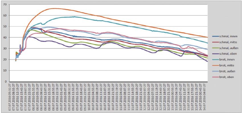
tragende Bühnenkonstruktion) schließlich im Juli 2016
                                                                                  in einem Großversuch im Maßstab 1:1 auf dem Gelände

                                                                                                                                                     TOPICS
                                                                                  der Wasserhaltung Haus Aden getestet.

                                                                                  8.1  Versuchsaufbau
                                                                                 Der Betonierversuch sollte die Eignung des Schalungs-
                                                                                 systems, die Eignung der entwickelten Betonrezeptur
                                                                                 und die Eignung der tragenden Bühnenkonstruktion
                                                                                 nachweisen. Dazu wurde auf dem Betriebsgelände der
                                                                                 Wasserhaltung Haus Aden zunächst eine Betonplat-
                                                                                 te hergestellt, um die Lasten aus dem Betonierversuch
                                                                                 in den Untergrund abzutragen. Auf dieser Betonplatte
                                                                                 wurde dann eine Außenschalung aufgestellt, welche die
                                                                                 Schachtwandung simuliert. Die Schalung wurde über
                                                                                 Streben nach außen abgestützt und der Betondruck da-
                                                                                 mit sicher abgetragen. Innerhalb dieser Außenschalung
                                                                                 (Durchmesser 4,5 m), wurde dann die Kletterschalung
    Fig. 10. Casing ring replicates the shaft wall.                              mit einem Durchmesser von 2,7 m exzentrisch angeord-
    Bild 10. Schalung als Schachtwand. Photo/Foto: RAG
                                                                                 net. Durch die Wahl der angegebenen Durchmesser und
                                                                                 die exzentrische Anordnung wird der aus der Schacht-
to be used for the preliminary skin had to exhibit a low degree of      schiefstellung resultierende, ungünstigste Betonierzustand im
shrinkage and would have to develop a rapid load-bearing capac-         Schacht 2 Friedlicher Nachbar abgebildet (Bild 10).
ity. It should also have a consistency capable of ensuring an even
spread and an effective envelopment of the shaft fittings.              8.2 Betonierversuch
      On the basis of these parameters several different formulas       In einem ersten Abschnitt, wurde zunächst eine Betonsäule von
were tested under laboratory conditions and the most suitable           2,25 m Höhe betoniert (Bild 11). Dazu wurde der obere Schalungs-
mix was then selected by agreement with the specialists.                ring der Kletterschalung exzentrisch in der Außenschalung plat-
                                                                        ziert und auf der Betonplatte gegen Verrutschen gesichert. Das
8      Verification by full-scale trial                                 Einbringen des Transportbetons erfolgte mittels einer Autobe-
In order to verify the material's suitability a full-scale trial was    tonpumpe mit Verteilermast. So wurde die Ausgangssituation
finally carried out in July 2016 at the Haus Aden pumping station       für den fortlaufenden Betoniervorgang mit der Kletterschalung
site, the aim being to investigate the interplay between all the        dargestellt.
components involved (concrete formula, formwork system and                  Für den eigentlichen Betonierversuch wurde die Kletterscha-
load-bearing platforms).                                                lung auf der geplanten Bühnenkonstruktion aufgebaut. Diese
                                                                        Bühne wurde für den Versuch geringfügig modifiziert. Die ge-
8.1 Test setup                                                          planten Hängestreben wurden durch eine Rohrkonstruktion mit
The concreting test sought to verify the suitability of the form-       Kreuzverstrebungen ersetzt. Die einzelnen Bühnenebenen wur-
work system, the applicability of the newly developed concrete          den mit einem Bohlenbelag versehen. Zusätzlich wurden unter
formula and the effectiveness of the supporting plat-
forms. To achieve this a slab of concrete was first built on
the grounds of the Haus Aden pumping station in order
to divert the loads generated by the concreting test into
the substrate. An outer ring of casing was then set up on
the concrete slab to simulate the walls of the shaft. This
casing was supported by a series of external struts that
would allow it safely to retain the pressure of the con-
crete. The climbing formwork, which was 2.7 m in diam-
eter, was then positioned eccentrically within the outer
casing (diameter 4.5 m). These diameters and the eccen-
tric arrangement of the formwork were deliberately cho-
sen to replicate the unfavourable concreting conditions
prevailing in Friedlicher Nachbar shaft 2 because of the
shaft tilt (Figure 10).

8.2 Concreting trial
The first part of the trial involved the pouring of a con-     Fig. 11. The first casting section.
                                                               Bild 11. Erster Betonierabschnitt. Photo/Foto: RAG
crete column 2.25 m in height (Figure 11). To achieve this

                                                                                                     Mining Report Glückauf 156 (2020) No. 2   131
the upper ring of the climbing form-
work was positioned eccentrically
within the outer casing and firmly se-
cured on the concrete slab to prevent
any risk of slipping. The ready-mixed
concrete was then poured in using a
truck-mounted concrete pump with
a placing boom. This represented the
starting position for the ongoing cast-
ing operation for the climbing form-
work.
     For the actual concrete casting
test the climbing formwork was built
up on the intended platform structure.
This stage was slightly modified for
the trial. The suspended bracing struts
were replaced by a tubular construc-
tion with cross stays. The individual
platform levels were provided with
decking. 1,000 mm-long props were
                                            Fig. 12. Drawing showing the position of the measuring points (3).
also fitted beneath the supporting
                                            Bild 12. Skizze zur Lage der Messstellen (3).
structure of the pouring platform. This
allowed the concreting system to be
dropped down into the start pipe. The climbing formwork was                 der Trägerkonstruktion der Betonierbühne Stützen mit 1.000
thereby lowered 1,070 mm into the start pipe (the 2,250 mm con-             mm Länge montiert. Dies ermöglichte das Absetzen des Beto-
creted plinth minus the 1,000 mm of prop length minus the 180               niersystems in der Startröhre. Die Kletterschalung wurde somit
mm profile thickness of the supporting structure for the climbing           1.070 mm tief in der Startröhre abgesetzt (2.250 mm betonierter
deck). This corresponded to the procedure that was planned for              Sockel minus 1.000 mm Stützenlänge minus 180 mm Profilstärke
the future shaft backfilling operation. The additional props were           der Trägerkonstruktion der Kletterbühne). Dies entspricht dem
brought in to avoid the need for a mobile crane for suspending              geplanten Betriebsablauf während der späteren Schachtverfül-
the concreting system during the casting test. When it is being             lung. Die zusätzlichen Stützen wurden angebracht, um während
deployed in the shaft the concreting system is suspended by a               des Betonierversuchs auf einen Mobilkran zum Aufhängen des
rope from a suitably sized platform winch. The deployment and               Betoniersystems verzichten zu können. Während des Einsatzes
subsequent withdrawal of the formwork is then carried out by                im Schacht hängt das Betoniersystem am Seil einer entsprechend
truck-mounted crane using the original anchor point on the con-             dimensionierten Bühnenwinde. Das Einsetzen und das spätere
creting stage.                                                              Ziehen der Schalung erfolgt dann an dem originalen Anschlag-
    The climbing formwork was braced in the described position              punkt auf der Betonierbühne mittels Autokran.
and aligned using the struts arranged around its upper edge. The                Die Kletterschalung wurde in der beschriebenen Position ver-
seal was inflated with a normal foot-operated air pump. These               spannt und mithilfe der am oberen Rand der Schalung angeord-
were the preparations that were put in place for testing the con-           neten Streben ausgerichtet. Die aufblasbare Dichtung wurde mit
creting system.                                                             einer handelsüblichen Fußluftpumpe aufgeblasen. Somit war das
                                                                            Betoniersystem für den Versuch vorbereitet.
8.3 Measurement programme
Numerous measuring transducers were installed following the             8.3 Messprogramm
assembly of the concreting system (Figure 12). Temperature sen-         Im Anschluss an den Aufbau des Betoniersystems wurden
sor heads were placed in the interspace between the outer casing        zahlreiche Messwertaufnehmer installiert (Bild 12). Im Zwi-
and the climbing formwork. These supplied information on the            schenraum zwischen Außen- und Kletterschalung wurden
development of hydration heat. Strain gauges were also fitted           Temperaturmessköpfe angeordnet. Diese liefern Erkenntnisse
to the outer casing in order to investigate the adhesion behav-         über die Hydratationswärmeentwicklung. Zusätzlich wurden
iour between the mass concrete block and the shaft wall. Pres-          an der Außenschalung Dehnungsmessstreifen angebracht, um
sure measuring pads, which were applied to the inner face of            das Haftungsverhalten eines massigen Betonkörpers an einer
the outer casing, were used to provide information on pressure          Schachtwand zu untersuchen. Druckmesskissen, angebracht an
development at the casing system during the concrete pouring            der Innenseite der Außenschalung, sollen Erkenntnisse über die
process. After the concrete pour test had been completed, the           Druckentwicklung auf das Schalungssystem während des Be-
outer casing removed and the climbing formwork withdrawn the            toniervorganges liefern. Nach Abschluss der Probebetonierung,
entire concrete body was left readily accessible for further inves-     dem Entfernen der Außenschalung und dem Ziehen der Kletter-
tigations. As the concrete column hardens core drillings can be         schalung ist der gesamte Betonkörper für weitere Untersuchun-

132   Mining Report Glückauf 156 (2020) No. 2
gen frei zugänglich. Über Kern-
                                                                                                               bohrungen können während des

                                                                                                                                                          TOPICS
                                                                                                               Aushärtens der Betonsäule wei-
                                                                                                               tere Erkenntnisse über die Festig-
                                                                                                               keitsentwicklung der eingesetzten
                                                                                                               Betonrezeptur gewonnen werden.
                                                                                                                    Das messtechnische Konzept
                                                                                                               (3) wurde von der LPI in enger Ab-
                                                                                                               stimmung mit der DMT aufge-
                                                                                                               stellt. Die LPI übernahm auch die
                                                                                                               Auswertung und Dokumentation
                                                                                                               des Versuchs.
                                                                                                                   Für die Durchführung des Be-
                                                                                                               tonierversuchs (Bild 13) wurde der
                                                                                                               Beton von der RAG-eigenen Beton-
                                                                                                               anlage hergestellt und mit Trans-
                                                                                                               portfahrzeugen angeliefert. Eine
                                                                                                               Kontrolle durch die LPI stellte da-
                                                                                                               bei vor Auslieferung der einzelnen
 Fig. 13. Concreting test (left: planned scenario; right: reality).
                                                                                                               Chargen die Qualität sicher. Bei Er-
 Bild 13 Betonierversuch (links: Planung; rechts: Realität). Source/Quelle: RAG                                reichen des Einsatzorts wurde vor
                                                                                                               dem Entleeren des Transportfahr-
                                                                                                               zeugs in die beiden Betonpumpen
taken to obtain further findings on the strength development of                   das Ausbreitmaß jeder Charge bestimmt, um die vorgesehene
the concrete formula used.                                                        Konsistenzklasse F5/F6 trotz des langen Transportwegs von Au-
    The metrological concept used (3) was set up by the LPI in                    guste Victoria Schacht 9 nach Haus Aden sicher einhalten zu
close coordination with the DMT. The LPI was also responsible for                 können. Das Einbringen des Betons erfolgte mit zwei Autobeton-
evaluating and documenting the test.                                              pumpen, deren Verteilermasten den Beton in den zu verfüllenden
    The concrete used for the pouring test (Figure 13) was pro-                   Raum einbrachten. Dies entspricht den für die Schachtverfüllung
duced in RAG's own concrete plant and delivered to the site by                    geplanten Verfüllleitungen.
truck. The LPI carried out quality control checks before the indi-                    Der Betoniervorgang, wurde in ca. 5 h durchgeführt. Das ent-
vidual batches were delivered. On arrival at the deployment site,                 spricht einer Betoniergeschwindigkeit von 1,0 bis 1,1 m/h. Nach
and before the material was discharged from the truck into the                    einer Aushärtedauer von 16 h wurde die Kletterschalung, wie im
two concrete pumps, the flow spread of each batch was estab-                      späteren Einsatz vorgesehen, planmäßig gezogen.
lished in order to ensure that the requirements of the specified                      Die Beobachtung des Fließverhaltens des Betons während
consistency class of F5/F6 were still being met, and this in spite of             des Betoniervorgangs wurde durch zwei seitlich neben dem Ver-
the long haulage distance from Auguste Victoria shaft 9 to Haus                   suchsaufbau angeordnete Treppentürme sowie eine diese ver-
Aden. Concrete placement was effected by two truck-mounted                        bindende Gerüstbrücke ermöglicht.
pumps with booms that were able to direct the material into the
target zone. These correspond to the filling pipes that would be                  8.4 Auswertung
used for the actual shaft backfill operation.                                     Nach Auswertung aller Messungen und Materialuntersuchun-
    The concrete pour was completed in about 5 hours, which rep-                  gen lässt sich das Ergebnis wie folgt zusammenfassen (3).
resented a pouring rate of 1.0 to 1.1 m/h. After a setting time of 16
h the climbing formwork was withdrawn according to plan, as it                    8.4.1  Betonrezeptur
would be in the real operation later.                                             Die aus den Laborversuchen abgeleitete Versuchsrezeptur hat die
    During the pour the flow behaviour of the concrete was ob-                    Anforderungen Verarbeitbarkeit, Ausschalfestigkeit am nächsten
served from two scaffold towers that had been erected on either                   Morgen und Endfestigkeit im Wesentlichen erfüllt. Sie kann da-
side of the test setup and from a bridgeway connecting the two.                   her als Basis für weitere Untersuchungen herangezogen wer-
                                                                                  den. Gewisse Änderungen im Anforderungsprofil, wie z. B. Tem-
8.4 Assessment                                                                    peraturrandbedingungen oder Fahrzeit der Transportfahrzeuge,
After all the measurements and material investigations had been                   können über die Zusatzmitteldosierung eingestellt werden. Bei
analysed the outcome of the test was summarised as follows (3).                   signifikant anderen Randbedingungen wie Änderung der Aus-
                                                                                  gangsstoffe oder kalte Bedingungen/heiße Bedingungen kann
8.4.1  Concrete formula                                                           aus technischen Gründen eine entsprechende Modifikation der
The experimental formula developed from the laboratory tests                      Rezeptur erforderlich sein. In Bezug auf die Hydratationswär-
essentially met the various requirements in respect of workabil-                  meentwicklung besteht ebenfalls noch Optimierungspotential
ity, next-day demoulding strength and final strength. It can there-               (Bild 14).

                                                                                                          Mining Report Glückauf 156 (2020) No. 2   133
Fig. 14. Development of
                                                                                                                concrete temperature (3).
                                                                                                                Bild 14. Entwicklung der
                                                                                                                Betontemperatur (3).

fore be used as a basis for further trials. Certain modifications to     8.4.2  Betonherstellung
the requirements profile, e. g. temperature boundary conditions          Mit der semimobilen RAG-Mischanlage kann auch ein solch an-
and truck journey times, can be configured via the additive dos-         spruchsvoller Beton grundsätzlich hergestellt werden. Der Qua-
ing process. Any other significant alteration in the boundary con-       litätssicherungsaufwand des verwendeten C25/30-Betons ist
ditions, such as changes to the source materials or deployment           höher als bei üblichen Schachtverfüllungen mit B5- oder B25-Ma-
in cold conditions/hot conditions, may for technical reasons re-         terial (B5 < C8/10; B25 C20/25). Eine entsprechende betontechnolo-
quire an appropriate modification to the formula. There is also          gische Unterstützung mindestens bei neuen Arbeitsabschnitten
still room for potential improvement in terms of hydration heat          oder Rezepturanpassungen, z. B. Änderung der Ausgangsstoffe,
development (Figure 14).                                                 wird empfohlen. Die Fahrzeit des Betons betrug im Versuch rund
                                                                         eine Stunde. Dafür muss der Beton entsprechend länger verar-
8.4.2  Concrete production                                               beitbar gehalten werden. Grundsätzlich sollte aber die Mischan-
Even a high-specification concrete such as that used here can be         lage möglichst nah am Einbauort positioniert werden. Die hier
produced by RAG’s own semi-mobile mixing plant. The quality as-          getestete Fahrzeit von einer Stunde ist bereits ungünstig und
surance effort required for this C25/30 concrete is greater than         sollte nicht überschritten werden. Bei Strecken mit starkem Stra-
that for conventional B5 or B25 shaft backfill material (B5 < C8/10;     ßenverkehrsaufkommen ist ggf. über einen Einbau während der
B25 C20/25). Appropriate concrete-technology support is there-           Nacht nachzudenken.
fore recommended, at least where new work sections or formula
adjustments are concerned, such as alterations to the source ma-         8.4.3  Betoneinbau
terials. For this particular trial the concrete travel time was about    Bei Verwendung von zwei Einbauleitungen (Bild 15) verteilte sich
one hour. This meant that the concrete had to remain workable            der Beton (8 mm Größtkorn, Rundkorn) bei Konsistenzklasse F6
for a correspondingly longer time. However, the mixing plant             (Konsistenzbereich F1 = steif bis F6 = sehr fließfähig) und im obe-
should normally be positioned as close as possible to
the placement site. The transit time of one hour at-
tempted here is generally unfavourable and should
not be exceeded. If the haulage route to be used is
prone to traffic congestion it may be necessary to con-
sider a night-time concreting operation.

8.4.3  Concrete placement
When two filler pipes were used (Figure 15) the con-
crete (8 mm max grain size, round) of consistency
class F6 (consistency range F1 = stiff to F6 = free flow-
ing), with F5 used in the upper zone, spread readily
out over the formwork. Using individual batches of
stiffer F4 material did not appreciably affect the over-
all picture. A softer consistency could have been em-
ployed but this would have meant an increase in the
formwork pressure and could have presented prob-
lems in respect of setting behaviour and demoulding          Fig. 15. Placement under way with two concrete pumps.
                                                             Bild 15. Betoneinbau mit zwei Betonpumpen. Photo/Foto: RAG
strength development.

134    Mining Report Glückauf 156 (2020) No. 2
In principle the aim is to place the concrete as rapidly as pos- ren Bereich von F5 gut in der Schalung. Einzelne Chargen steiferen
sible and with few or no interruptions. However, the concreting Materials F4 wirken sich nicht nennenswert auf das Gesamtbild
TOPICS
test also showed that even an interruption of around 1.5 h to the aus. Eine weichere Einbaukonsistenz könnte eingestellt werden,
pour had no significant effect on the overall result. In spite of the würde aber erhöhend auf den Schalungsdruck wirken und könn-
relative sensitive nature of the concrete the placement system te problematisch hinsichtlich des Erstarrungsverhaltens und der
used in the full-scale trial proved to be fairly resilient. The com- Ausschalfestigkeitsentwicklung sein.
pressive strength values measured at the finished structure aver- Grundsätzlich ist ein möglichst zügiger, unterbrechungsfrei-
aged out at around 45 N/mm2 after 28 days, thereby meeting the er Betoneinbau anzustreben. Bei der Versuchsbetonage hat sich
static requirements with a fair amount to spare. aber auch gezeigt, dass sogar eine Unterbrechung des Einbaus
von rd. 1,5 h keine deutlichen Auswirkungen auf das Gesamtbild
9 Initial use of climbing formwork hat. Beim Großversuch erwies sich das Einbaukonzept trotz des
at Fürst Leopold 1 shaft relativ sensiblen Betons vergleichsweise robust. Die am Bauwerk
After the full-scale trial with the climbing formwork had been gemessenen Druckfestigkeiten erreichten Werte von im Mittel
completed the system was then successfully deployed at Fürst rd. 45 N/mm2 nach 28 Tagen und erfüllten die statischen Anforde-
Leopold 1 shaft. This shaft is 6.50 m in diameter and 903 m in rungen mit einer deutlichen Reserve.
depth. The climbing formwork was used to pour some 18,000 m3
of concrete into the shaft from the abutment at the 670 m level. 9 Ersteinsatz der Kletterschalung
The application of the climbing formwork under real conditions im Schacht Fürst Leopold 1
showed that this system constitutes a highly suitable method for Nach der Erprobung der Kletterschalung im Großversuch wur-
shaft backfilling. de die Kletterschalung erfolgreich im Schacht Fürst Leopold 1
eingesetzt. Der Schacht Fürst Leopold 1 hat einen Durchmesser
von 6,50 m und eine Teufe von 903 m. Ab dem Widerlager in ei-
ner Teufe von 670 m wurden unter Einsatz der Kletterschalung
ca. 18.000 m3 Beton in den Schacht eingebracht. Der Einsatz der
Kletterschalung unter realen Bedingungen hat gezeigt, dass die
Kletterschalung eine gut geeignete Methode zur Schachtverfül-
lung ist.
References / Quellenverzeichnis Authors / Autoren
(1) Opitz, D.; Nilotzki, S. (2014): Machbarkeitsstudie zum Einsatz einer Dipl.-Ing. Carsten Linka, ZPP Ingenieure AG, Bochum,
Kletterschalung im Rahmen der Schachtverfüllung Friedlicher Dipl.-Ing. Dieter Hardes, RAG Aktiengesellschaft, Essen
Nachbar 2.
(2) Friedrich, T.; Schepp, T. (2016): Schacht Friedlicher
Nachbar 2 – Gutachten zum Umbau des Schachtes zum
Wasserhaltungsstandort.
(3) Lohaus, L.; Petersen, L. (2015): Gutachterliche Stellungnahme
Betontechnologie.
(4) VersatzV (2002): Verordnung über den Versatz von Abfällen unter
Tage.
Mining Report Glückauf 156 (2020) No. 2 135Sie können auch lesen