Parallel Interface USP-PI Parallel interface USP-PI

Die Seite wird erstellt Luca Hiller
 
WEITER LESEN
Parallel Interface USP-PI Parallel interface USP-PI
Parallel Interface USP-PI
                                                                                                                          Parallel interface USP-PI

                                                                                                                          Bedienungsanleitung
                                                                                                                          Instruction manual

                                         2.000 / L.D. / 10.2004 / Teile-Nr. 1163294 / BZ-Nr. 700 00-35V900 / Ausgabe 02

K. A. Schmersal GmbH
Industrielle Sicherheitsschaltsysteme
Möddinghofe 30
D - 42279 Wuppertal

Postfach 24 02 63
D - 42232 Wuppertal

Telefon    +49 - (0)2 02 - 64 74 - 0
Telefax    +49 - (0)2 02 - 64 74 - 100
E-Mail     info@schmersal.de
Internet   www.schmersal.com
Deutsch
Seiten 3 – 30

English
Pages 31 – 58
Parallel Interface USP-PI

Inhaltsverzeichnis                                                                              Seite
Einleitung . . . . . . . . . . . . . . . . . . . . . . . . . . . . . . . . . . . . . . . . . . . . . 4
    Allgemeine Hinweise . . . . . . . . . . . . . . . . . . . . . . . . . . . . . . . . . . 4
Haftungsausschluss . . . . . . . . . . . . . . . . . . . . . . . . . . . . . . . . . . . . 4
   Der Hersteller. . . . . . . . . . . . . . . . . . . . . . . . . . . . . . . . . . . . . . . . 4
Zu Ihrer persönlichen Sicherheit. . . . . . . . . . . . . . . . . . . . . . . . . . . 5
Montage der programmierbaren Einheit USP-PI . . . . . . . . . . . . 6
  Einsetzen und Anschließen des USP-PI im Schaltschrank . . . . . . 6
  Klemmenbelegung . . . . . . . . . . . . . . . . . . . . . . . . . . . . . . . . . . . . 6
Funktion der programmierbaren Einheit USP-PI . . . . . . . . . . . . . . 7
   Begriffserklärung . . . . . . . . . . . . . . . . . . . . . . . . . . . . . . . . . . . . . 7
Die Menüfunktionen des USP-PI. . . . . . . . . . . . . . . . . . . . . . . . . . . 8
   Auf die Menüs zugreifen . . . . . . . . . . . . . . . . . . . . . . . . . . . . . . . 8
   Die Struktur der Menüfunktionen . . . . . . . . . . . . . . . . . . . . . . . . . 9
Schachtprofil . . . . . . . . . . . . . . . . . . . . . . . . . . . . . . . . . . . . . . . . . 10
Auf die Menüs zugreifen . . . . . . . . . . . . . . . . . . . . . . . . . . . . . . 11
   Sprache auswählen . . . . . . . . . . . . . . . . . . . . . . . . . . . . . . . . . . 11
   Lernfahrt aktivieren . . . . . . . . . . . . . . . . . . . . . . . . . . . . . . . . . . 12
   Lernfahrt durchführen . . . . . . . . . . . . . . . . . . . . . . . . . . . . . . . . 13
   Schachtkopie berechnen . . . . . . . . . . . . . . . . . . . . . . . . . . . . . . 14
   Bündigwerte manuell eingeben . . . . . . . . . . . . . . . . . . . . . . . . . 15
   Ebene verschieben . . . . . . . . . . . . . . . . . . . . . . . . . . . . . . . . . . 16
   Ebene löschen . . . . . . . . . . . . . . . . . . . . . . . . . . . . . . . . . . . . . . 17
   Spur verschieben . . . . . . . . . . . . . . . . . . . . . . . . . . . . . . . . . . . . 18
   Signal verschieben. . . . . . . . . . . . . . . . . . . . . . . . . . . . . . . . . . . 19
   Signal einfügen . . . . . . . . . . . . . . . . . . . . . . . . . . . . . . . . . . . . . 20
   Signal löschen . . . . . . . . . . . . . . . . . . . . . . . . . . . . . . . . . . . . . . 21
   Flanke verschieben . . . . . . . . . . . . . . . . . . . . . . . . . . . . . . . . . . 22
   Bündig . . . . . . . . . . . . . . . . . . . . . . . . . . . . . . . . . . . . . . . . . . . . 23
   Schachtkopie löschen . . . . . . . . . . . . . . . . . . . . . . . . . . . . . . . . 23
Monitoring . . . . . . . . . . . . . . .        .   . . . . . . . . . . . . . . . . . . . . . . . . . 24
  Anzeige der Flankenwerte . .                  .   . . . . . . . . . . . . . . . . . . . . . . . . . . 24
  Aktuelle Position . . . . . . . . .           .   . . . . . . . . . . . . . . . . . . . . . . . . . . 25
  Fehlerstatus . . . . . . . . . . . . .        .   . . . . . . . . . . . . . . . . . . . . . . . . . . 25
  Schachtinformation . . . . . . .              .   . . . . . . . . . . . . . . . . . . . . . . . . . . 25
  Fahrprofile . . . . . . . . . . . . . .       .   . . . . . . . . . . . . . . . . . . . . . . . . . . 25
  Programminformation . . . . .                 .   . . . . . . . . . . . . . . . . . . . . . . . . . . 25
Testfunktion . . . . . . . . . . . . . . . . . . . . . . . . . . . . . . . . . . . . . . . . 26
   Ausgänge setzen . . . . . . . . . . . . . . . . . . . . . . . . . . . . . . . . . . . . 26
Fehlermeldungen des USP-PI . . . . . . . . . . . . . . . . . . . . . . . . . . . . 26
Maßnahmen zur Einrichtung und Inbetriebnahme . . . . . . . . . . . . 27
Anschlusspläne . . . . . . . . . . . . . . . . . . . . . . . . . . . . . . . . . . . . . . . 28
Technische Daten . . . . . . . . . . . . . . . . . . . . . . . . . . . . . . . . . . . . . 30

                                                                                                                      3
Parallel Interface USP-PI

        Einleitung
        Allgemeine Hinweise
        Das Parallel-Interface USP-PI wurde nach dem Stand der Technik gebaut. Diese Bedienungsanlei-
        tung ist von allen Personen zu beachten, die mit dem USP-PI arbeiten oder dieses montieren.

        Es ist zwingend notwendig, diese Bedienungsanleitung den zuständigen Monteuren oder dem In-
        standhaltungspersonal jederzeit zugänglich zu machen.
        Grundvoraussetzung für den sicherheitsgerechten Umgang und den störungsfreien Betrieb dieses
        Systems ist die Kenntnis über die grundlegenden und speziellen Sicherheitsvorschriften in der
        Fördertechnik, speziell in der Aufzugtechnik.

        Das USP-PI darf nur seiner Bestimmung gemäß verwendet werden. Insbesondere ist zu beachten,
        dass:
        • keine Änderungen oder Ergänzungen am USP-PI durchgeführt werden dürfen.

        Haftungsausschluss
        Der Hersteller haftet nicht gegenüber dem Käufer dieses Produkts oder Dritten für Schäden, Ver-
        luste, Kosten oder Ausgaben, die vom Käufer oder Dritten verursacht wurden, aufgrund von Unfall,
        Mißbrauch des Produktes, falscher Montage oder unerlaubten Änderungen, Reparaturen oder
        Neuerungen. Ebenso sind Garantieleistungen in solchen Fällen ausgeschlossen.
        Die technischen Daten entsprechen dem aktuellen Stand. Druckfehler, Irrtümer und Änderungen
        bleiben dem Hersteller vorbehalten.

        Der Hersteller
        K. A. Schmersal GmbH
        Industrielle Sicherheitsschaltsysteme
        Möddinghofe 30
        D - 42279 Wuppertal

        Telefon    +49 - (0)2 02 - 64 74 - 0
        Telefax    +49 - (0)2 02 - 64 74 - 1 00
        E-Mail     info@schmersal.de
        Internet   www.schmersal.com

        Bei Bedarf erhalten Sie weitere Ausgaben dieser Bedienungsanleitung unter dieser Adresse.

4
Parallel Interface USP-PI

Zu Ihrer persönlichen Sicherheit
Diese Bedienungsanleitung vermittelt Ihnen wichtige Sicherheitshinweise und Informatio-
nen, die zur einwandfreien Inbetriebnahme des Parallel-Interface USP-PI erforderlich sind.
Lesen Sie diese Bedienungsanleitung vollständig und aufmerksam.

• Der Monteur muß mit den grundlegenden Vorschriften über Arbeitssicherheit und Unfallverhü-
  tung vertraut und in die Handhabung von Förderanlagen eingewiesen sein.

• Benutzen Sie bei der Montage als auch bei der Instandsetzung nur einwandfreies
  Werkzeug.

• Schließen Sie das USP-PI nur im spannungslosen Zustand an.

• Führen Sie die Lernfahrt ausschließlich im Modus „Inspektionsfahrt“ durch.

• Achten Sie bei der Lernfahrt darauf, dass sich niemand im Schacht befindet.

                                                                                           5
Parallel Interface USP-PI

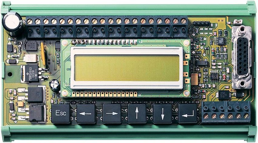
Montage des parallel Interface USP-PI

     Der Kommunikationsbaustein USP-PI bildet die universelle Schnittstelle für Steuerun-
     gen, die keine seriellen Positionsinformationen verarbeiten können. Mit Hilfe des
     USP-PI werden Magnetschaltersignale nachgebildet.

Einsetzen und Anschließen des USP-PI im Schaltschrank

     Das USP-PI ist gemäß der Schutzart IP 00 konstruiert und somit
     in einem geschlossenen Schaltschrank zu installieren.

     Setzen Sie das USP-PI an einen freien und geeigneten Platz auf die Normschiene im
     Schaltschrank auf, an dem es vor Verschmutzung geschützt ist. Das Profil ist so
     ausgeführt, dass Sie die Platine einfach auf die Schiene aufklipsen können.

     Elektronische Bauteile können sich im Betrieb erwärmen.
     Nicht berühren oder abdecken!

     Schließen Sie das USP-PI gemäß des im Anhang befindlichen Schaltplanes an.

6
Parallel Interface USP-PI

Funktion des Parallel Interface USP-PI
Der Kommunikationsbaustein USP-PI dient zur Eingabe und Veränderung aller notwendigen
Parameter, die zur Berechnung der Schaltpunkte einer Schachtkopie notwendig sind. Der Bau-
stein USP-PI erlaubt zusätzlich, neben der manuellen Eingabe der Schaltpunkte, ein Erfassen
der Bündigwerte mittels eines Lerntasters und einer damit verbundenen Lernfahrt. Als Grund-
lage zur Berechnung der Schaltpunkte dient ein Schachtprofil.

Begriffserklärung
Bündigwert:          Position, in der Boden der Fahrkabine und Etagenboden bündig
                     zueinander stehen.

Ebene:               Alle Flanken der Schalter, die sich einer Etage (Ebene) zuordnen lassen.

Flanke:              Schaltpunkt eines Ausgangs des USP-PI, der dem Schaltpunkt eines
                     Magnetschalters entspricht. Man unterscheidet zwischen fallenden und
                     steigenden Flanken. Der Bereich zwischen den Flanken wird Signal ge-
                     nannt.

Positionswert:       Längeninformation des USP-Systems in Millimetern. Diese Information
                     ist die Entfernung zwischen Sender und Empfänger.

Schachtkopie:        Abbildung aller Schalter im Aufzugschacht. Im USP-PI werden deren
                     Schaltpunkte in Tabellenform abgelegt.

Schachtkopierung:    Vorgang, der die Ausgänge entsprechend programmierter Schaltpunkte
                     umschaltet. Die Schaltpunkte werden entsprechend der Schachtkopie
                     festgelegt.

Schachtprofil:       Beschreibung einer Schalteranordnung im Aufzugschacht, die unab-
                     hängig von der Anzahl der Etagen ist. USP-PI nutzt dies als Grundlage,
                     um aus den Bündigwerten alle Flanken der Ebenen zu berechnen.

Signal:              Schaltsignal eines Ausgangs, das aus Einschalt- und Ausschaltflanke
                     besteht. Dieses Signal entspricht dem Signalverlauf eines Magnet-
                     schalters.

Spur:                Jeder Ausgang des USP-PI bildet eine Spur. In einer Spur liegen alle
                     Signale bzw. Flanken eines Ausgangs.

                                                                                                7
Parallel Interface USP-PI

            Die Menüfunktionen des USP-PI
            Der Kommunikationsbaustein USP-PI bietet Ihnen eine Reihe von Funktionen, die es er-
            möglichen, die Berechnungen der Schaltpunkte auf ihr Schachtprofil genauestens anzu-
            passen.
            Die Menüfunktionen sind in Menüs und Untermenüs gegliedert, auf die Sie durch Betätigen
            der Taster zugreifen können.

            Auf die Menüs zugreifen
            Im Folgenden erhalten Sie eine Beschreibung der Tastaturbelegung des USP-PI. Der Zugriff
            auf die einzelnen Menüs erfolgt grundsätzlich nach dem gleichen Prinzip. Mit Hilfe der ne-
            benstehenden Menüstruktur sowie dem Funktionprinzip der Tastaturbelegung können Sie
            auf alle Menüs und deren Funktionen zugreifen.

            Rückschritt
    Esc
            Abbruch der ausgewählten Menüfunktion

            Setzen des Cursors auf eine ausgesuchte Stelle wie
            – eine Ziffer
            – ein Vorzeichen
            – eine Einstelloption

            Auswahl einer Menüfunktion
            Erhöhung bzw. Verminderung eines ausgewählten Feldes oder eines Zustandes wie:
            – eine Ziffer
            – ein Vorzeichen
            – eine Einstelloption

            Bestätigen
            – einer ausgewählten Menüfunktion
            – eines eingestellten Wertes
            – einer gewählten Option

                        Esc

8
Parallel Interface USP-PI

Die Struktur der Menüfunktionen
Alle Parametereinstellungen und Anzeigen des USP-PI sind in der unten aufgeführten Menüstruktur hinter-
legt. Die Texte im Display können mehrsprachig angezeigt werden. Alle Positionsangaben erfolgen in mm,
Geschwindigkeiten in m/s, Verzögerungen / Beschleunigungen in m/s2.
      Eb = n  V=nm/s
      0101010101110000
                       Sprache
                                 Englisch
                                 Deutsch

                       Monitoring
                                 Flankenwerte
                                          Flankenwerte für Ebene und Spur

                                 aktuelle Position
                                            akt. Position ( mm )

                                 Fehlerstatus
                                            Fehler-Aufzeichnung Draht
                                                      Aufzeichnung aktiv

                                            Draht
                                                      Drahtfehler / Anzahl / Position

                                            Signal
                                                      Signalfehler / Anzahl

                                 Schacht
                                            Förderhöhe ( mm )
                                            Anzahl Ebenen

                                 Fahrprofile
                                            USP-Receiver oben/unten
                                            eingestelltes Profil
                                            eingestellte Vnenn
                                            eingestellte Vnenn2
                                            eingestellte Verzögerung
                                            gemessene Vmax
                                            aktuelle V
                                            aktuelle Beschleunigung

                                 Programminfo
                                         Programmversion mit Datum/Zugangscode

                       Einstellungen
                                  Zugangscode (siehe Punkt 21)
                                          Inbetriebnahme
                                                     Bündigwerte eingeben
                                                               Lernfahrt
                                                                         bestehende Werte löschen nein / ja?
                                                                                  Receiver oben / unten
                                                                                            Lernfahrt aktiv

                                                               manuelle Eingabe
                                                                          bestehende Werte löschen nein / ja?
                                                                                   Receiver oben / unten
                                                                                             Nummer des Bündigwertes
                                                                                                        Bündigwerteingabe in mm
                                                      Schachtkopie berechnen
                                                               Profilnummer
                                                                          V nenn
                                                                                   (V nenn2)
                                                                                             a nenn
                                                                                                        Berechnen ja / nein?
                                                      Schachtkopie ändern
                                                               Flanke verschieben
                                                                          Ebenennummer
                                                                                   Spurnummer
                                                                                             obere / untere Flanke
                                                                                                        verschieben nach oben / unten
                                                                                                                  verschieben um ( mm )
                                                               Signal verschieben
                                                                          Ebenennummer
                                                                                   Spurnummer
                                                                                             verschieben nach oben / unten
                                                                                                        verschieben um ( mm )
                                                               Signal einfügen
                                                                          Spurnummer
                                                                                   untere Flanke ( mm )
                                                                                             obere Flanke ( mm )
                                                               Signal löschen
                                                                          Spurnummer
                                                                                   Ebenennummer
                                                                                             Signal löschen nein / ja?
                                                               Spur verschieben
                                                                          Spurnummer
                                                                                   verschieben nach oben / unten
                                                                                             verschieben um ( mm )
                                                               Bündig

                                                                   Ebene verschieben
                                                                             Ebenennummer
                                                                                     verschieben nach oben / unten
                                                                                               verschieben um (mm)
                                                                   Ebene löschen
                                                                             Ebenennummer
                                                                                     Ebene löschen ja / nein

                                                      Schachtkopie löschen
                                                               löschen nein / ja?

                                            Ausgänge setzen
                                                     alle Ausgänge schalten
                                                               alle Ausgänge ein- / ausschalten

                                                      Ausgang einzeln schalten
                                                               Status Ausgänge (1010101010101010)

                                                      Kurzschluss testen
                                                                Y1 - Y16 / + = o.k. (++++++++++++++++)

                                                                                                                                            9
Parallel Interface USP-PI

                                                                                          Schachtprofil
                                                                                          Als Grundlage zur Berechnung der Schaltpunkte dient ein
                                                                                          Schachtprofil, um aus den Bündigwerten alle Flanken der Ebe-
                                                                                          nen zu berechnen. Jedes Schachtprofil besteht aus Berech-
                                                                                          nungsformeln für die einzelnen Schaltpunkte der Ausgänge.

                                                                                          Die Abstände der Signale zu den Bündigwerten ergeben sich
                                                                                          aus den eingegebenen Werten für Verzögerung und Nenn-
                                                                                          geschwindigkeiten.

                                                                                          1
1                                                                                         Schachtprofile
                                                                                          Werksseitig sind die Schachtprofile 1 und 2 im USP-PI hinter-
                                                                                          legt. Bei Schachtprofil 0 ist eine Berechnung der Schachtkopie
Y1   Y2   Y3   Y4   Y5   Y6   Y7   Y8   Y9   Y10 Y11 Y12 Y13 Y14 Y15 Y16
                                                                                          nicht möglich. Die einzelnen Signale müssen hier manuell ein-
                                                      Bündigwert oberste Etage
                                                                                          gegeben werden.
                                                         Bündigwert Etage 1-(n-1)

                                                                                          Das Einfügen eines Signals in eine bereits durch eine errechnete
                                                         Bündigwert unterste Etage

                                                                                          Schachtkopie belegte Spur ist nicht möglich.
 Bündig   Impuls    Korrektur Tür- Nach-
                              zone holung

                                                                                          Y1:    Bündigsignal abwärts
                                                                                          Y2:    Bündigsignal aufwärts
                                                                                          Y3:    Impuls / Verzögerung aufwärts
Schachtprofil 1                                                                           Y4:    Impuls / Verzögerung abwärts
                                                                                          Y5:    Korrektur Signal oben
                                                                                          Y6:    Korrektur Signal unten
                                                                                          Y7:    Türzone
Y1   Y2   Y3   Y4   Y5   Y6   Y7   Y8   Y9   Y10 Y11 Y12 Y13 Y14 Y15 Y16
                                                          Bündigwert oberste Etage
                                                                                          Y8:    Nachholung aufwärts
                                                                                          Y9:    Nachholung abwärts
                                                              Bündigwert Etage 1-(n-1)

                                                                                          Y10:   Impuls / Verzögerung Vnenn 2 aufwärts (nur Profil 2)
                                                              Bündigwert unterste Etage   Y11:   Impuls / Verzögerung Vnenn 2 abwärts (nur Profil 2)

 Bündig   Impuls 1 Korrektur Tür- Nach-       Impuls 2
                             zone holung

Schachtprofil 2

10
Parallel Interface USP-PI

                                Auf die Menüs zugreifen, anhand
                                von Beispielen
                                Im Folgenden werden Beispiele gezeigt, wie Sie auf bestimmte
                                Menüfunktionen zugreifen können, welche Tätigkeiten notwen-
                                dig sind um Lernfahrten durchzuführen, wie Korrekturen durch-
                                geführt und wie Schachtkopierungen berechnet werden. Des-
                                weiteren wird erläutert wie Signale, Spuren und Flanken ver-
                                schoben werden können.

                                2
2                               Sprache auswählen
                                In dem Menü „Sprache“ können Sie auswählen, in welcher
    System not                  Sprache die Texte angezeigt werden sollen. Bei der ersten Inbe-
    configured                  triebnahme erscheint im Display „System not configured“.

                                            System not
                                            configured

                                            language
    Deutsch
    gewählt

                                            English                         English
                                                                            choosen

                                            Deutsch                         Deutsch
Schrittweise zurück mit   Esc                                               gewählt

                                                                                            11
Parallel Interface USP-PI

                                     3
3                                    Lernfahrt aktivieren
                                     Mit der Lernfahrt werden die Bündigwerte der einzelnen Etagen
                                     vom USP-System eingelesen und im Kommunikationsbaustein
     Einstellungen
                                     USP-PI weiter verarbeitet. Das USP-PI berechnet dabei mit Hilfe
                                     eines Schachtprofils alle Schaltpunkte der Schachtkopierung.

                                            Navigieren Sie anhand der Menüstruktur zum Menüpunkt
                                            „Einstellungen“.

                                                Einstellungen

      Lernfahrt

                                                Zuggangscode
                                                0000
       Wenn Sie auf andere oder
       weitere Menüfunktionen zu-
       greifen möchten, navigieren
       Sie anhand der Menüstruktur
                                                                            Zugangscode
       zu dem gewünschten Menü-                                             falsch

       punkt.

                                                                            Der Zugangscode ist fest im
                                                Inbetriebnahme
                                                                            ROM hinterlegt und kann nicht
                                                                            durch den Anwender
                                                                            verändert werden.

                                                Bündigwerte
                                                eingeben

                                                Lernfahrt

                                                bestehende Werte
                                                löschen? Nein

                                                bestehende Werte
                                                löschen? Ja

                                                Bündigwerte
                                                gelöscht

                                                USP-Receiver                Lernfahrt
                                                oben                        aktiv

                                                USP-Receiver                Lernfahrt
Schrittweise zurück mit   Esc                   unten                       aktiv

12
Parallel Interface USP-PI

4   Lernfahrt durchführen

                      Menüpunkt „Lernfahrt aktiv“

                        Anfahren einer Haltestelle
                      im Modus „Inspektionsfahrt“

                        Drücken des Lerntasters

                                                     Lerntaster leuchtet
                                                     zur Bestätigung

                            Alle Haltestellen                   nein
                                gelernt?

                                   ja

                      Menüpunkt „Lernfahrt aktiv“
                          durch Drücken der
                        „ESC“-Taste verlassen

    Ein gelernter Bündigwert kann durch längeres Drücken des Lerntasters wieder gelöscht werden.
    Dies ist aber nur möglich, wenn die Position der Kabine nicht verändert wurde.
    Zur Bestätigung erlischt die LED im Lerntaster.

                                                                                                   13
Parallel Interface USP-PI

                                5
5                               Schachtkopie berechnen
                                Mit dem Menü „Schachtkopie berechnen“ aktivieren Sie die Be-
                                rechnungen aller Schaltpunkte der Schachtkopierung. Diese
     Lernfahrt aktiv
                                Menüfunktion kann aus den Menüpunkten „Lernfahrt aktiv“
                                oder, mittels der manuellen Eingaben der Bündigwerte, aus dem
                                Menüpunkt „Bündigwert“ aufgerufen werden.

                                          In diesem Beispiel navigieren Sie anhand der Menü-
                                          struktur zum Menüpunkt „Lernfahrt aktiv“.

                                            Lernfahrt aktiv
     Schachtkopie
     berechnet
                                    Esc

                                            Schachtkopie
                                            berechnen

                                            Profil 1

                                                                      Es können mehrere Profile
                                                                      angelegt werden. Werksseitig
                                                                      sind zwei Profile hinterlegt.
                                            Profil n

                                            V nenn                    Einstellwert Nenn-
                                            00.0 m/s                  geschwindigkeit: 0,1 - 10 m/s

                                                                      Die Eingabe der Geschwindigkeit
                                                                      „Vnenn 2“ ist nur möglich, wenn
                                                                      weitere Profile angelegt sind.

                                            a nenn
                                                                       Einstellwert Nennverzögerung:
                                            0.0 m/ss                   0,1 - 1,2 m/s2

                                            Berechnen?
                                            Ja

                                            Schachtkopie
Schrittweise zurück mit   Esc               berechnet

14
Parallel Interface USP-PI

                                6
6                               Bündigwerte manuell eingeben
                                Mit dem Menü „manuelle Eingabe“ können Sie die Bündigwerte
     Bündigwerte
                                anhand einer Maßzeichnung der Aufzuganlage manuell eingeben.
     eingeben                   Die Werte entsprechen dem Abstand zwischen Sender und
                                Empfänger.

                                      Navigieren Sie anhand der Menüstruktur zum Menü-
                                      punkt „Bündigwerte eingeben“.
                                        Bündigwerte
                                        eingeben

     Schachtkopie
     berechnen                          Lernfahrt

                                        manuelle Eingabe

                                        bestehende Werte
                                        löschen? Nein

                                        bestehende Werte
                                        löschen? Ja

                                        Bündigwerte
                                        gelöscht

                                        USP-Receiver
                                        oben

                                        USP-Receiver
                                        unten

                                        Bündigwert     1
                                        0 mm

                                        Bündigwert     1
                                        000000 mm
                                                               Einstellwert: 1 mm - 140.000 mm

                                        Bündigwert     n
                                        000000 mm
                                                               Einstellwert: 1 - 45 Bündigwerte

                                        Bündigwert     n
                                        0 mm

                                                               Die weitere Vorgehensweise ist in
                                                               Punkt 5 „Schachtkopie berechnen“
Schrittweise zurück mit   Esc           Schachtkopie
                                                               erläutert.
                                        berechnen

                                                                                                   15
Parallel Interface USP-PI

                                       7
7                                      Ebene verschieben
                                       Die Verschiebung einer Ebene ist erforderlich, wenn die Position
     Schachtkopie
                                       der Aufzugkabine in einer Etage nicht bündig ist. Dabei werden
     ändern                            alle zu der Ebene gehörenden Signale gleich verschoben. Das
                                       Profil und die Bündigwerte der anderen Etagen bleiben bei die-
                                       ser Verschiebung unverändert.

                                             Navigieren Sie anhand der Menüstruktur zum Menüpunkt
                                             „Schachtkopie ändern“.

                                                  Schachtkopie
                                                  ändern
     Ebene
     verschoben

                                                  Flanke verschieben

      Das Verschieben einer Ebene
                                                   5x
      ist nur möglich, wenn Profil 1
      oder 2 gewählt sind.                        Ebene verschieben

                                                  Ebene    1

                                                  Ebene    45
                                                                             Ebene wählen, die verschoben
                                                                             werden muss.

                                                  verschieben
                                                  nach oben

                                                  verschieben
                                                  nach unten

      Ebene 1 befindet sich, unab-                verschieben um
                                                  0000 mm

      hängig von der Richtung der
      Lernfahrt, immer unten.

Zurück nach „Ebene n“ mit    Esc                  Ebene
                                                  verschoben

16
Parallel Interface USP-PI

                                  8
8                                 Ebene löschen
                                  In diesem Menüpunkt können alle Signale einer Ebene gleich-
    Schachtkopie                  zeitig gelöscht werden. Dies ist z.B. notwendig, wenn bei der
    ändern                        Lernfahrt ein Bündigwert zuviel gelernt wurde. Da nur errech-
                                  nete Signale, nicht aber der Bündigwert gelöscht wird, sind die
                                  Signale nach einer Neuberechnung der Schachtkopie wieder
                                  vorhanden.

                                        Navigieren Sie anhand der Menüstruktur zum Menüpunkt
                                        „Schachtkopie ändern“.

    Ebene
    gelöscht                                 Schachtkopie
                                             ändern

                                             Flanke
                                             verschieben

                                             6x

                                             Ebene
                                             löschen

                                             Ebene      1

                                             Ebene      X               X = höchste Ebene

                                             Ebene löschen?
                                             Nein

                                             Ebene löschen?
                                             Ja

                                             Ebene
Zurück nach „Ebene n“ mit   Esc              gelöscht

                                                                                              17
Parallel Interface USP-PI

                                   9
9                                  Spur verschieben
                                   Die Verschiebung einer Spur ist erforderlich, wenn die Aufzug-
     Schachtkopie                  kabine z.B. in jeder Etage nach einer Abwärts- bzw. Aufwärts-
     ändern                        fahrt nicht bündig an der Etage steht. Bei der Verschiebung
                                   einer Spur bleiben die Länge der Signale sowie ihre Abstände
                                   zueinander unverändert.

                                          Navigieren Sie anhand der Menüstruktur zum Menü-
                                          punkt „Schachtkopie ändern“.
                                              Schachtkopie
                                              ändern

     Spur
     verschoben

                                              Flanke
                                              verschieben

                                               4x

                                              Spur        
                                              verschieben

                                              Spur   Y      1

                                                                        Spur wählen, die verschoben
                                              Spur       15
                                                                        werden muss.

                                              verschieben
                                              nach oben

                                              verschieben
                                              nach unten

                                              verschieben um
                                              0000 mm

                                              Spur   
Zurück nach „Spur (Y)“ mit   Esc              verschoben

18
Parallel Interface USP-PI

                                     10
10                                   Signal verschieben
                                     Die Verschiebung eines Signals ist erforderlich, wenn die Auf-
    Schachtkopie                     zugkabine z.B. in nur einer Etage nach einer Abwärts- bzw. Auf-
    ändern                           wärtsfahrt nicht bündig an der Etage steht. Bei der Verschie-
                                     bung eines Signals bleibt die Länge des Signals unverändert.

                                            Navigieren Sie anhand der Menüstruktur zum Menüpunkt
                                            „Schachtkopie ändern“.
                                                Schachtkopie
                                                ändern

    Signal
    verschoben
                                                Flanke
                                                verschieben

      Eine Verschiebung, die eine
      Überlappung mit einem an-                 Signal
                                                verschieben
      deren Signal in derselben
      Spur darstellen würde, führt
      zu einer Fehlermeldung.
                                                Ebene         1

                                                                          Ebene wählen, in der
                                                Ebene         45
                                                                          verschoben werden muss.

                                                Spur       1

                                                                          Spur wählen, in der
                                                Spur       15
                                                                          verschoben werden muss.

                                                verschieben
                                                nach oben

                                                verschieben
                                                nach unten

                                                verschieben um
                                                0000 mm

                                                Signal
Zurück nach „Ebene n“ mit    Esc                verschoben

                                                                                                    19
Parallel Interface USP-PI

                                11
11                              Signal einfügen
                                Eine Schachtkopie kann durch das Einfügen von Signalen er-
     Schachtkopie               weitert oder neu erzeugt werden, um kundenspezifische An-
     ändern                     forderungen zu erfüllen. Signale können in alle nicht belegten
                                Spuren eingefügt werden. Bei Profil 0 ist keine Spur belegt.

                                       Navigieren Sie anhand der Menüstruktur zum Menüpunkt
                                       „Schachtkopie ändern“.

                                           Schachtkopie
                                           ändern

     Signal
     eingefügt
                                           Flanke
                                           verschieben

                                            2x

                                           Signal
                                           einfügen

                                           Spur         1

                                                                      Spur wählen, in der ein Signal
                                           Spur         16
                                                                      eingefügt werden soll

                                           untere Flanke
                                           000000 mm

                                           obere Flanke
                                           000000 mm

                                           Signal
Schrittweise zurück mit   Esc              eingefügt

20
Parallel Interface USP-PI

                                12
12                              Signal löschen
                                Ein in eine freie Spur eingefügtes Signal kann komplett wieder
    Schachtkopie                gelöscht werden. Da die Ebenen von unten gezählt werden,
    ändern                      werden dabei die Nummern der Ebenen der höherliegenden
                                Signale um eins reduziert.

                                       Navigieren Sie anhand der Menüstruktur zum Menüpunkt
                                       „Schachtkopie ändern“.

                                           Schachtkopie
                                           ändern

    Signal
    gelöscht
                                           Flanke
                                           verschieben

                                            3x

                                           Signal
                                           löschen

                                                                      Spur wählen, in der
                                           Spur        1
                                                                      gelöscht werden muss.

                                           Spur        16

                                           Ebene          1
                                                                      Ebene wählen, in der
                                                                      gelöscht werden muss.

                                           Ebene          45

                                           Signal löschen?
                                           Nein

                                           Signal löschen?
                                           Ja

                                           Signal
Schrittweise zurück mit   Esc              gelöscht

                                                                                              21
Parallel Interface USP-PI

                                     13
13                                   Flanke verschieben
                                     Die Verschiebung einer Flanke ist erforderlich, wenn die Aufzug-
     Schachtkopie                    kabine z.B. bei der Schleichfahrt in einer Etage zu weit bzw.
     ändern                          nicht weit genug fährt.

                                            Navigieren Sie anhand der Menüstruktur zum Menüpunkt
                                            „Schachtkopie ändern“.

                                                Schachtkopie
                                                ändern

     Flanke                                     Flanke
     verschoben                                 verschieben

      Eine Verschiebung, die eine               Ebene           1

      Überlappung mit einem
      anderen Signal in derselben
      Spur darstellen würde, führt                                        Ebene wählen, in der
                                                Ebene           45
                                                                          verschoben werden muss.
      zu einer Fehlermeldung.

                                                Spur         1

                                                                          Spur wählen, in der
                                                Spur         15
                                                                          verschoben werden muss.

                                                obere Flanke

                                                untere Flanke
                                                                          Sonderfall
                                                                          Korrekturschalter!

                                                                          Beim oberen Korrekturschalter
                                                verschieben
                                                                          sollte nur der Wert „untere Flan-
                                                nach oben                 ke“ verändert werden.

                                                                          Beim unteren Korrekturschalter
                                                                          sollte nur der Wert „obere Flan-
                                                verschieben               ke“ veränderte werden.
                                                nach unten

                                                verschieben um
                                                0000 mm

                                                Flanke
Zurück nach „Ebene n“ mit    Esc
                                                verschoben

22
Parallel Interface USP-PI

14   Bündig

     Um die Positioniergenauigkeit im Zusammenhang mit den Einstellungen des Antriebes zu beur-
     teilen, kann das Menü „Bündig“ verwendet werden.

     Hier wird die aktuelle Ebene und die Positionsabweichung in Bezug auf den eingelernten
     Bündigwert angezeigt. Werte mit negativem Vorzeichen bedeuten, dass sich die Kabine unter-
     halb des Bündigwertes befindet.
.

15   Schachtkopie löschen

     Im Menü „Schachtkopie löschen“ können alle gespeicherten Bündigwerte und Signale gelöscht
     werden. Dies ist notwendig, wenn ein bereits programmiertes Gerät für eine neue Anwendung
     genutzt wird.

                                                                                             23
Parallel Interface USP-PI

                                        Monitoring
                                        Im Menü Monitoring ist die Anzeige aller eingegebenen oder
                                        vom USP-PI berechneten Daten möglich. Eine Veränderung
                                        oder Eingabe kann nicht erfolgen.

                                        16
16                                      Anzeige der Flankenwerte
                                              Navigieren Sie anhand der Menüstruktur zum Menüpunkt
                                              „Monitoring“.
     Monitoring
                                                   Monitoring

                                                   Flankenwerte

     Flankenwerte                                  Eb 1
Parallel Interface USP-PI

17   Aktuelle Position anzeigen

     In diesem Menüpunkt wird die aktuelle Position der Kabine angezeigt. Der Wert entspricht dem
     Abstand zwischen Sender und Empfänger.

18   Fehlerstatus

     Durch Anwahl des Menüpunktes „ Aufzeichnung aktiv“ und Durchführung einer Inspektionsfahrt
     ist es möglich, Fehler des Übertragungssignals sowie Drahtfehler anzuzeigen. Die Anzahl bzw.
     die Nummer und Position des Fehlers wird in den Menüpunkten Draht oder Signal angezeigt.

19   Schachtinformation

     Im Menüpunkt „Schacht“ wird die Förderhöhe und die Anzahl der Ebenen angezeigt.

20   Fahrprofile

     Der Menüpunkt „Fahrprofile“ ermöglicht es die eingestellten oder gemessenen Werte für
     Geschwindigkeit, Beschleunigung oder Verzögerung anzuzeigen. Außerdem wird das eingestell-
     te Profil und die Lage des USP-Receivers dargestellt.

21   Programminfo

     In diesem Menü befinden sich Informationen zur Programmversion und der Zugangscode für
     das Menü „Einstellungen“.

           Der Zugangscode ist 0202.

                                                                                              25
Parallel Interface USP-PI

Testfunktion

22       Ausgänge setzen

         Durch die Testfunktion „Ausgänge setzen“ können die Ausgänge des USP-PI und die
         Verdrahtung zur Steuerung geprüft werden. Dabei ist es möglich die Ausgänge einzeln oder
         komplett zu schalten. Zusätzlich können alle Ausgänge auf Kurzschluss getestet werden.

Fehlermeldungen des USP-PI

         Wird ein Fehler durch das USP-PI erkannt, werden die Ausgänge 1-15 ein- und der
         Ausgang 16 ausgeschaltet.

         Fehler Kommunikation

         Es findet keine Kommunikation zwischen dem USP-Empfänger und dem USP-PI statt,
         oder die Kommunikation ist gestört.

         Mögliche Ursachen:
         - Empfängerkabel ist nicht aufgesteckt oder beschädigt
         - Nicht ausreichend geglättete Spannungsversorgung (siehe Technische Daten)

         Fehler Ultraschall - Puls

         Der USP-Empfänger erkennt kein oder ein gestörtes Ultraschall-Signal.

         Mögliche Ursachen:
         - Signaldraht ist beschädigt (Knickstellen)
         - Fehlerhafte Montage des Drahtes im Dämpfer
         - Keine Verbindung zwischen Sender und Empfänger (Senderkabel nicht aufgesteckt oder Adern
           des Hängekabels vertauscht; LED-Anzeige des Senders kontrollieren)
         - Unzureichende Spannungsversorgung (siehe Technische Daten)

         Fehler Ausgänge

         Ursache:
         - Ein oder mehrere Ausgänge sind kurzgeschlossen.
         - Die einzelnen Ausgänge können wie unter Punkt 22 beschrieben überprüft werden.

26
Parallel Interface USP-PI

Maßnahmen zur Einrichtung und Inbetriebnahme

      Im Folgenden erhalten Sie eine Kurzanleitung über die grundlegensten Schritte bei der
      Einrichtung und Inbetriebnahme des USP-PI.

      1.   USP-Empfänger mit 15-poliger Sub-D-Leitung anschließen.

      2.   USP-Sender über 2 Pole der Schraubklemmleiste (T+, T-) anschließen –
           die Triggerleitung zum Sender ist hergestellt.

      3.   Aufzugsteuerung über 15 Pole der Schraubklemmleiste (15 kurzschlussfeste
           24 V Ausgänge - Y1 bis Y15) anschließen.

      4.   Spannungsversorgung (24 V DC) über zwei Pole an der Schraubklemmleiste anlegen
           (A1+, A2–).

      5.   Lerntaster über 4 Pole der unteren Schraubklemmleiste anschließen
           (Le, L+ / GND, Y16) und Lernfahrt durchführen, oder alternativ Bündigwerte manuell
           eingeben.

      6.   Schachtkopie berechnen.

      7.   Feinjustierung

                                                                                                27
Parallel Interface USP-PI

            Anschlussplan

USP-PI
                     Schachtkopf                   Schaltschrank
                      USP Empfänger

                                                          USP-PI

                     Aufzugkabine
                      USP Sender

                      Korrektur-
                      sensor

                      Lerntaster

                                                                             * nur bei USP 100

            Klemmenbelegung

             Klemmenbelegung
             A1+, A2–:                Spannungsversorgung 24 VDC
             Sub-D 15 polig:          Anschluss USP-Empfänger
             T+, T-:                  Anschluss USP-Sender; Triggerleitung
             Y16, GND, L+, Le:        Anschluss Lerntaster
             Y1-Y15:                  Anschluss Aufzugsteuerung

28
Parallel Interface USP-PI

           Anschlussplan

USP-PI/N
                  Schachtkopf                                          Schaltschrank
                   USP Empfänger                                        Y1 Y2 Y3 Y4 Y5 Y6 Y7 Y8 Y9 Y10Y11Y12Y13Y14Y15Y16 K+ GND

                                                                          A1
                                                                          A2
                                            Sub-D                 15             USP-PI                           Sub-D
                                            15 pol.                                                               15 pol.

                                                                                                              T+ T- Y16 GNDL+ Le

                  Aufzugkabine
                   USP Sender                              X1
                        1 / 2 Trigger   1      BN           T+
                                        2     WH
                                                                                                      6(8)*
                   3 / 4 GND_Trigger    3      BU           T-
                                        4      BK

                                                      BN    K+
                   Korrektur-
                   sensor                             BU    GND

                                                      YE    Le
                   Lerntaster

                                                      OR    L+
                                                      RD    L+

                                                      BU    Y16

                                                                                                                            * nur bei USP 100

           Klemmenbelegung

           Klemmenbelegung
           A1+, A2–:                                   Spannungsversorgung 24 VDC
           Sub-D 15 polig:                             Anschluss USP-Empfänger
           T+, T-:                                     Anschluss USP-Sender; Triggerleitung
           Y16, L+, Le:                                Anschluss Lerntaster
           Y1-Y15:                                     Anschluss Aufzugsteuerung

                                                                                                                                    29
Parallel Interface USP-PI

Technische Daten
Technische Daten         USP-PI
Störaussendung:          EN 50081-1, EN 12015
Störfestigkeit:          IEC 61000-6-2, EN 12016
Gehäusematerial:         PVC
Befestigung:             Schnellbefestigung für Normschiene nach
                         EN 50022 und EN 50035
Schraubanschluss:        0,5 … 1,5 mm2
Schutzart:               IP 00
Betriebsspannung Ue:     24 VDC +15% / –10%, Restwelligkeit 5%
Betriebsstrom ohne
Ausgänge Ie:             0,15 A

Eingang Le:              Lerntaster
• Maximaler Strom:       35 mA
• Eingangswiderstand:    ca. 3 kΩ gegen GND
• Eingangspegel "1":     10 ... 30 V
• Eingangspegel "0":     0 ... 2 V

Ausgänge Y1 – Y 16:      kurzschlussfest, p-schaltend
• Max. Leitungslänge:    30 m
• Ausgangsspannung Ua:   Ue – 1 V
• Ausgangsstrom Ia:      max. 100 mA pro Ausgang
Überspannungs-
kategorie:               III
Verschmutzungsgrad:      2
Schwingungsfestigkeit:   10 … 55 Hz / 0,0375 mm
Schockfestigkeit:        15 g / 11 ms
Umgebungstemperatur:     –5 °C … +60 °C
Lager- und Transport-
temperatur:              –25 °C ... +70 °C

30
Parallel interface USP-PI

Table of contents                                                                              Page
Introduction . . . . . . . . . . . . . . . . . . . . . . . . . . . . . . . . . . . . . . . . . . 32
    General information . . . . . . . . . . . . . . . . . . . . . . . . . . . . . . . . . . 32
Exclusion of liability . . . . . . . . . . . . . . . . . . . . . . . . . . . . . . . . . . . 32
   The manufacturer. . . . . . . . . . . . . . . . . . . . . . . . . . . . . . . . . . . . 32
Concerning your personal safety . . . . . . . . . . . . . . . . . . . . . . . . . 33
Mounting of the parallel interface USP-PI . . . . . . . . . . . . . . . . 34
  Installing and connecting the USP-PI in the control cabinet. . . . 34
  Terminal connections . . . . . . . . . . . . . . . . . . . . . . . . . . . . . . . . . 34
Functions of the parallel interface USP-PI . . . . . . . . . . . . . . . . . 35
   Explanation of terms . . . . . . . . . . . . . . . . . . . . . . . . . . . . . . . . . 35
Menu functions of the USP-PI . . . . . . . . . . . . . . . . . . . . . . . . . . . . 36
  Accessing the menus. . . . . . . . . . . . . . . . . . . . . . . . . . . . . . . . . 36
  Structure of the menu functions. . . . . . . . . . . . . . . . . . . . . . . . . 37
Driving profile. . . . . . . . . . . . . . . . . . . . . . . . . . . . . . . . . . . . . . . . . 38
Accessing the menus. . . . . . . . . . . . . . . . . . . . . . . . . . . . . . . . . 39
   Select language . . . . . . . . . . . . . . . . . . . . . . . . . . . . . . . . . . . . . 39
   Activate teach-in drive . . . . . . . . . . . . . . . . . . . . . . . . . . . . . . . . 40
   Teach-in drive . . . . . . . . . . . . . . . . . . . . . . . . . . . . . . . . . . . . . . 41
   Calculate shaft copy . . . . . . . . . . . . . . . . . . . . . . . . . . . . . . . . . 42
   Input levelling values manually. . . . . . . . . . . . . . . . . . . . . . . . . . 43
   Moving a levelling value . . . . . . . . . . . . . . . . . . . . . . . . . . . . . . . 44
   Delete level . . . . . . . . . . . . . . . . . . . . . . . . . . . . . . . . . . . . . . . . 45
   Moving a trace . . . . . . . . . . . . . . . . . . . . . . . . . . . . . . . . . . . . . . 46
   Moving a signal . . . . . . . . . . . . . . . . . . . . . . . . . . . . . . . . . . . . . 47
   Insertion of a signal . . . . . . . . . . . . . . . . . . . . . . . . . . . . . . . . . . 48
   Delete a signal . . . . . . . . . . . . . . . . . . . . . . . . . . . . . . . . . . . . . . 49
   Moving an edge . . . . . . . . . . . . . . . . . . . . . . . . . . . . . . . . . . . . . 50
   Level . . . . . . . . . . . . . . . . . . . . . . . . . . . . . . . . . . . . . . . . . . . . . 51
   Delete shaft copy . . . . . . . . . . . . . . . . . . . . . . . . . . . . . . . . . . . . 51
Monitoring . . . . . . . . . . . . . . .       .   . . . . . . . . . . . . . . . . . . . . . . . . . 52
  Display of the edge values . .               .   . . . . . . . . . . . . . . . . . . . . . . . . . . 52
  Current position . . . . . . . . . .         .   . . . . . . . . . . . . . . . . . . . . . . . . . . 53
  Error status . . . . . . . . . . . . .       .   . . . . . . . . . . . . . . . . . . . . . . . . . . 53
  Shaft information . . . . . . . . .          .   . . . . . . . . . . . . . . . . . . . . . . . . . . 53
  Driving profiles. . . . . . . . . . .        .   . . . . . . . . . . . . . . . . . . . . . . . . . . 53
  Program info . . . . . . . . . . . .         .   . . . . . . . . . . . . . . . . . . . . . . . . . . 53
Test function. . . . . . . . . . . . . . . . . . . . . . . . . . . . . . . . . . . . . . . . 54
   Set outputs . . . . . . . . . . . . . . . . . . . . . . . . . . . . . . . . . . . . . . . . 54
Fault signals from the USP-PI . . . . . . . . . . . . . . . . . . . . . . . . . . . . 54
Action for setting up and starting up . . . . . . . . . . . . . . . . . . . . . . 55
Circuit diagrams . . . . . . . . . . . . . . . . . . . . . . . . . . . . . . . . . . . . . . 56
Technical data . . . . . . . . . . . . . . . . . . . . . . . . . . . . . . . . . . . . . . . . 58

                                                                                                                    31
Parallel interface USP-PI

        Introduction
        General information
        The parallel interface USP-PI was built to state of the art-technology. This instruction manual is to
        be followed by all persons working with the USP or installing it.

        It is extremely important that this instruction manual is made available at all times to the relevant
        technicians, engineers or servicing and maintenance personnel.
        The basis prerequisite for safe handling and trouble-free operation of this system is a sound
        knowledge of the basic and special safety regulations concerning conveyor technology, and
        elevators in particular.

        The USP-PI may only be used for its intended purpose. Note in particular that:
        • No changes or additions may be made at the USP-PI.

        Exclusion of liability
        The manufacturer is not liable with respect to the buyer of this product or to third parties for dam-
        age, loss, costs or work incurred as a result of accidents, misuse of the product, incorrect installa-
        tion or illegal changes, repairs or additions. Claims under warranty are likewise excluded in such
        cases.
        The technical data is the latest available. The manufacturer accepts no liability arising from
        printing errors, mistakes and changes.

        The manufacturer
        K. A. Schmersal GmbH
        Industrielle Sicherheitsschaltsysteme
        Möddinghofe 30
        D - 42279 Wuppertal

        Telefon +49 - (0)2 02 - 64 74 - 0
        Telefax +49 - (0)2 02 - 64 74 - 1 00
        E-Mail info@schmersal.de
        Internet www.schmersal.com

        If you need further copies of this instruction manual, you can obtain them from this address.

32
Parallel interface USP-PI

Concerning your personal safety
This instruction manual provides you with important safety details and information
required for proper starting-up of the USP-PI.
Carefully read through this instruction manual in full.

• The mechanic must be familiar with the basic regulations concerning safety at work and acci-
  dent prevention and have been suitably instructed in the handling of elevators.

• Only use tools that are in perfect condition for both installation and servicing work.

• Connect the USP-PI only in de-energized condition.

• Carry out the teach-in drive only in inspection travel mode.

• Take care that nobody is in the shaft during teach-in drive.

                                                                                            33
Parallel interface USP-PI

Mounting of the parallel interface USP-PI

     The communication module USP-PI forms the universal interface for controllers that
     cannot process serial positioning information. Signals of magnetic reed switches are
     simulated with the help of the USP-PI.

Installing and connecting the USP-PI in the
control cabinet

     The USP-PI is designed to protection type IP 00 and thus should be installed in a
     closed control cabinet.

     Install the USP-PI at a vacant and suitable point on the standard bar in the control cabi-
     net, where it cannot be soiled. The profile is designed so that you can simply clip the
     board onto the standard rail.

     Electronic components can heat up in operation.
     Do not touch or cover them!

     Connect the USP-PI as shown in the circuit diagram at the end of this mounting instruction.

34
Parallel interface USP-PI

Functions of the parallel interface USP-PI
The communication module USP-PI is used for input and modification of all the required para-
meters for calculation of the switching points of a shaft copy. In addition to manual input of the
switching points, the module USP-PI also allows the levelling values to be entered via a teach-
in button and the associated teach-in drive. A driving profile is used as the basis for calculation
of the switching points.

Explanation of terms
Levelling value:       Position at which the floor of the elevator cabin and the floor at that
                       particular storey are flush to one another.

Level:                 All the edges of the switches that can be allocated to a storey (level).

Edge:                  Switching point of an output from the USP-PI, which corresponds to the
                       switching point of a magnetic reed switch. A distinction is made between
                       rising and falling edges. The area between the edges is called the signal.

Positioning value:     Length information of the USP system in steps of one millimetre. This
                       information is the distance between the transmitter and the receiver.

Shaft copy:            Illustration of all the switches in the elevator shaft. The switching points
                       for these switches are stored in table form in the USP-PI.

Shaft copying:         The process by which the outputs switch over according to the corre-
                       sponding preprogrammed switching points. The switching points are
                       determined according to the shaft copy.

Driving profile:       Description of the switch arrangement in the elevator shaft, which is not
                       affected by the number of storeys. The USP-PI uses this as the basis to
                       calculate the levelling values of the levels.

Signal:                Switching signal of an output, consisting of the switching-on edge and
                       the switching-off edge. This signal corresponds to the signal gradient of
                       a magnetic reed switch.

Trace:                 Each output of the USP-PI forms a trace. All the signals and edges of an
                       output are included in a trace.

                                                                                                  35
Parallel interface USP-PI

            Menu functions of the USP-PI
            The communication module USP-PI offers a whole series of functions that allow you to
            modify the calculations of the switching points to your driving profile with the greatest pos-
            sible accuracy.
            The menu functions are sub-divided into menus and sub-menus that you can access by ac-
            tuating the buttons.

            Accessing the menus
            The following gives you a description of the keyboard layout of the USP-PI. Access to the
            individual menus is basically done on the same principle throughout. You can access all the
            menus and their functions with the aid of the menu structure shown here and the function
            principle of the keyboard layout.

            Back
     Esc
            Cancel the selected menu function

            Place the cursor on a desired point such as
            – a number
            – a preceding sign
            – a setting option

            Selection of a menu function
            Increasing or reducing a selected field or a state such as:
            – a number
            – a preceding sign
            – a setting option

            Confirm
            – a selected menu function
            – a set value
            – a selected option

                         Esc

36
Parallel interface USP-PI

Structure of the menu functions
All the parameter settings and displays of the USP-PI are stored in the menu structure shown below.
The texts in the display can be displayed in various languages. All positioning details are given in mm,
speeds in m/s, and deceleration / acceleration in m/s2.
      Eb = n  V=nm/s
      0101010101110000
                       language
                                  Englisch
                                  Deutsch

                       monitoring
                                 edge values
                                           edge values of level and trace

                                  current position
                                            current position ( mm )

                                  error status
                                             fault recording of wire
                                                        recording active

                                             wire
                                                       fault in wire / number / position

                                             signal
                                                       fault in signal / number

                                  shaft
                                             travel height ( mm )
                                             number of levels

                                  driving profiles
                                             USP-receiver top / bottom
                                             set profile
                                             set Vnom
                                             set Vnom2
                                             set deceleration
                                             measured Vmax
                                             current V
                                             current acceleration

                                  program info
                                            program version with date / access code

                       settings
                                  access code (see point 21)
                                           installation
                                                       enter levelling values
                                                                   teach-in drive
                                                                              delete existing values no / yes?
                                                                                         receiver top / bottom
                                                                                                    teach-in drive active

                                                                  manual input
                                                                             delete existing values no / yes?
                                                                                        receiver top / bottom
                                                                                                   number of levelling value
                                                                                                              enter levelling in mm
                                                       calculate shaft copy
                                                                  profile number
                                                                             V nom
                                                                                        (V nom2)
                                                                                                   a nom
                                                                                                              calculate yes / no?
                                                       change shaft copy
                                                                  move edge
                                                                             level number
                                                                                        trace number
                                                                                                   top / bottom edge
                                                                                                              move to top / bottom
                                                                                                                          move by ( mm )
                                                                  move signal
                                                                             level number
                                                                                        trace number
                                                                                                   move to top / bottom
                                                                                                              move by ( mm )
                                                                  insert signal
                                                                             trace number
                                                                                        bottom edge ( mm )
                                                                                                   top edge ( mm )
                                                                  delete signal
                                                                             trace number
                                                                                        level number
                                                                                                   delete signal no / yes?
                                                                  move trace
                                                                             trace number
                                                                                        move to top / bottom
                                                                                                   move by ( mm )
                                                                  level

                                                                    move level
                                                                               level number
                                                                                         move to top / bottom
                                                                                                    move by (mm)
                                                                    delete level
                                                                               level number
                                                                                         delete level yes / no?

                                                       delete shaft copy
                                                                 delete no / yes?

                                             set outputs
                                                       switch all outputs
                                                                  switch all outputs on / off

                                                       switch outputs individually
                                                                 status outputs (1010101010101010)

                                                       test short-circuit
                                                                  Y1 - Y16 / + = o.k. (++++++++++++++++)

                                                                                                                                                  37
Parallel interface USP-PI

                                                                                               Driving profile
                                                                                               A driving profile forms the basis of the calculation of the switch-
                                                                                               ing points, from which the levelling values of all the edges are
                                                                                               calculated. Each driving profile consists of calculation formulae
                                                                                               for the individual switching points of the outputs.

                                                                                               The distance of the signals to the levelling values is dependent
                                                                                               on the values entered for speed and deceleration.

                                                                                               1
1                                                                                              Driving profile
                                                                                               The driving profiles 1 and 2 are stored in the USP-PI at the
                                                                                               factory. With the driving profile 0 a calculation of the shaft copy
 Y1   Y2   Y3   Y4   Y5   Y6   Y7   Y8   Y9    Y10 Y11 Y12 Y13 Y14 Y15 Y16
                                                                                               is not possible. All signals have to put in manually.
                                                        Levelling value top floor

                                                         Levelling value floor 1-(n-1)
                                                                                               It is not possible to insert a signal in a trace already occupied
                                                                                               by a calculated shaft copy.
                                                         Levelling value bottom floor

 Level     Impulse   Revision Door Re-
                              zone levelling
                                                                                               Y1:    Levelling signal down
                                                                                               Y2:    Levelling signal up
                                                                                               Y3:    Impulse deceleration up
                                                                                               Y4:    Impulse deceleration down
Driving profile 1                                                                              Y5:    Reset signal up
                                                                                               Y6:    Reset signal down
                                                                                               Y7:    Door zone
                                                                                               Y8:    Relevel up
 Y1   Y2   Y3   Y4   Y5   Y6   Y7   Y8   Y9    Y10 Y11 Y12 Y13 Y14 Y15 Y16
                                                            Levelling value top floor
                                                                                               Y9:    Relevel down
                                                                                               Y10:   Impulse deceleration Vnom 2 up (profile 2 only)
                                                               Levelling value floor 1-(n-1)

                                                                                               Y11:   Impuls deceleration Vnom 2 down (profile 2 only)
                                                               Levelling value bottom floor

 Level     Impulse 1 Revision Door Re-       Impulse 2
                              zone levelling

Driving profile 2

38
Parallel interface USP-PI

                           Accessing the menus, on the basis
                           of examples
                           The following illustrates examples of how you can access spe-
                           cific menu functions, what actions are necessary to carry out
                           the teach-in drive operation, how to make corrections, and how
                           shaft copying is calculated.
                           In addition, an explanation is given of how to offset signals,
                           traces and edges.

                           2
2                          Select language
                           You can select from the ”Language” menu in which language
   System not              the text is to be displayed. ”System not configured” appears in
   configured              the display when the system is started up for the first time
                           during installation.

                                       System not
                                       configured

    English
    choosen                            language

                                       English                         English
                                                                       choosen

                                       Deutsch                         Deutsch
Back one step with   Esc                                               gewählt

                                                                                        39
Parallel interface USP-PI

                            3
3                           Activate teach-in drive
                            Teach-in drive is used to read in the levelling values for the indi-
                            vidual floors by the USP system and these are subsequently
     settings
                            processed in the communication module USP-PI. The USP-PI
                            calculates with the aid of a driving profile all the switching
                            points of the shaft copying.

                                   Navigate to menu item ”Settings” on the basis of the
                                   menu structure.

                                        settings

     teach-in drive

                                        access code
                                        0000

                                                                      access code
                                                                      wrong

                                                                     The access code is stored per-
                                        installation                 manently in ROM and cannot
                                                                     be changed by the user.

                                        enter
                                        levelling values

                                        teach-in drive

                                        delete existing
                                        values? no

                                        delete existing
                                        values? yes

                                        levelling values
                                        deleted

                                        USP-receiver                  teach-in drive
                                        top                           active

                                        USP-receiver                  teach-in drive
Back one step with   Esc                bottom                        active

40
Parallel interface USP-PI

4   Teach-in drive

                               Menu item
                          „teach-in drive active“

                          Travel to the first level
                       in „inspection travel“ mode

                        Push the teach-in button

                                                      Teach-in button lights up
                                                      as input confirmation

                                All levels                        no
                                learned?

                                   yes

                            Leave menu item
                        „teach-in drive active“ by
                        pushing the „Esc“-button

    A taught levelling value can be deleted by pressing the teach-in button for some seconds.
    This is only possible, if the position of the cabin has not been changed.
    For confirmation the LED in the teach-in button goes out.

                                                                                                        41
Parallel interface USP-PI

                            5
5                           Calculate shaft copy
                            Use menu item ”Calculate shaft copy” to activate the calcula-
     teach-in drive         tion of all switching points of the shaft copying. This menu
     active                 function can be called up from menu item ”Teach-in drive ac-
                            tive” or, by entering the levelling values manually, from menu
                            item ”Levelling value”.

                                      In this example you can navigate to menu item ”Teach-in
                                      drive active” on the basis of the menu structure.

                                         teach-in drive
     calculate                           active
     shaft copy
                                Esc

                                         calculate
                                         shaft copy

                                         profile 1

                                                                  Multiple profiles can be created.
                                                                  Two profiles are stored at the fac-
                                                                  tory.
                                         profile n

                                         V nom                    Rated speed,
                                         00.0 m/s                 setting values: 0.1 - 10 m/s

                                                                  It is only possible to input the
                                                                  speed ”Vnom 2”, if additional pro-
                                                                  files have been created.

                                         a nom                    Rated deceleration,
                                         0.0 m/ss                 setting values: 0.1 - 1,2 m/s2

                                         calculate?
                                         yes

                                         shaft copy
Back one step with   Esc                 calculated

42
Parallel interface USP-PI

                           6
6                          Input levelling values manually
                           You can input levelling values manually on the basis of the di-
     enter
                           mensional drawing of the elevator unit with the ”Manual input”
     levelling values      menu. All values correspond to the distance between transmit-
                           ter and receiver.

                                  Navigate to menu item ”Input levelling values” on the
                                  basis of the menu structure.
                                    enter
                                    levelling values

     calculate
     shaft copy                     teach-in drive

                                    manual input

                                    delete existing
                                    values? no

                                    delete existing
                                    values? yes

                                    levelling values
                                    deleted

                                    USP-receiver
                                    top

                                    USP-receiver
                                    bottom

                                    levelling value 1
                                    0 mm

                                    levelling value 1
                                    000000 mm
                                                            Setting value: 1 mm - 140.000 mm

                                    levelling value n
                                    000000 mm
                                                            Setting value: 1 - 45 levelling values

                                    levelling value n
                                    0 mm

                                                           The subsequent procedure is explained
Back one step with   Esc            calculate
                                                           in item 5 ”Calculate shaft copy”.
                                    shaft copy

                                                                                                     43
Parallel interface USP-PI

                                          7
7                                         Moving a level
                                          Moving a level is necessary, if the elevator cabin is not right
     change
                                          levelled at one floor. All signals of one level are moved simulta-
     shaft copy                           neously. The profile and the levelling values of the other floors
                                          remain unchanged after this move.

                                                Navigate to menu item ”Change shaft copy” on the basis
                                                of the menu structure.

                                                     change
                                                     shaft copy
     level
     moved

                                                     move edge

       Moving a level is only pos-
                                                      5x
       sible, if you have chosen
       profile 1 or 2.                               move level

                                                     level     1

                                                     level     45
                                                                                 Select the level at which a
                                                                                 correction is necessary.

                                                     move to
                                                     top

                                                     move to
                                                     bottom

                                                     move by
                                                     0000 mm

       Level 1 is always at the
       bottom, independent of the
       direction of the teach-in drive.

                                                     level
Back to ”level n” with    Esc                        moved

44
Parallel interface USP-PI

                               8
8                              Delete level
                               In this menu item it is possible to delete all signals of one level
   change                      at the same time. This can be necessary, if one extra, not de-
   shaft copy                  sired level has been learned during the teach-in drive. Recog-
                               nizing that only the calculated signals but not the levelling val-
                               ues are deleted, the signals will be given again after a new cal-
                               culation of the shaft copy.

                                      Navigate to menu item „Change shaft copy“ on the basis
                                      of the menu structure.

    level
    deleted                                change
                                           shaft copy

                                           move edge

                                           6x

                                           delete
                                           level

                                           level     1

                                           level     X                 X = top level

                                           delete level?
                                           no

                                           delete level?
                                           yes

                                           level
Back to ”level n” with   Esc               deleted

                                                                                               45
Parallel interface USP-PI

                                 9
9                                Moving a trace
                                 It is necessary to move a trace, if the elevator cabin does not
     change                      line up with the floor at each storey, e.g., after travelling up or
     shaft copy                  down. The length of the signals and their distances from each
                                 other remain unchanged when a trace is moved.

                                         Navigate to menu item ”Change shaft copy” on the
                                         basis of the menu structure.

                                             change
                                             shaft copy

     trace
     moved

                                             move edge

                                              4x

                                             move
                                             trace           

                                             trace     Y     1

                                                                          Select the trace in which a
                                             trace        15
                                                                          move is necessary.

                                             move to
                                             top

                                             move to
                                             bottom

                                             move by
                                             0000 mm

                                             trace
Back to ”Trace (Y)” with   Esc               moved     

46
Parallel interface USP-PI

                                       10
10                                     Moving a signal
                                       It is necessary to move a signal, if the elevator cabin does not
    change                             line up with the floor at a particular storey, e.g., after travelling
    shaft copy                         up or down. The length of a signal remains unchanged when it
                                       is moved.

                                              Navigate to menu item ”Change shaft copy” on the basis
                                              of the menu structure.
                                                   change
                                                   shaft copy

    signal
    moved
                                                   move edge

       A move which would lead to
       an overlapping of two signals               move signal

       in the same trace will induce
       an error message.

                                                   level           1

                                                                                 Select the level at which a move
                                                   level           45
                                                                                 is necessary.

                                                   trace        1

                                                                                 Select the trace in which a move
                                                   trace        15
                                                                                 is necessary.

                                                   move to
                                                   top

                                                   move to
                                                   bottom

                                                   move by
                                                   0000 mm

                                                   signal
Back to ”level n” with   Esc
                                                   moved

                                                                                                              47
Parallel interface USP-PI

                            11
11                          Insertion of a signal
                            It is possible to create or extend a shaft copy to meet customer
     change                 requirements by insertion of signals. You can insert signals in all
     shaft copy             free traces. Profile 0 is completely free.

                                    Navigate to menu item „Change shaft copy“ on the
                                    basis of the menu structure.

                                       change
                                       shaft copy

     signal
     inserted
                                       move edge

                                        2x

                                       insert
                                       signal

                                       trace      1

                                                                    Select the trace at which the
                                       trace      16
                                                                    signal insert

                                       bottom edge
                                       000000 mm

                                       top edge
                                       000000 mm

                                       signal
Back one step with   Esc               inserted

48
Parallel interface USP-PI

                           12
12                         Delete a signal
                           A signal which has been inserted in a free trace can be deleted
    change                 again completely. Because of the numbering of the levels from
    shaft copy             below, the numbers of the levels of higher signals will be redu-
                           ces by one.

                                  Navigate to menu item „ Change shaft copy“ on the
                                  basis of the menu structure.

                                      change
                                      shaft copy

    signal
    deleted
                                      move edge

                                       3x

                                      delete
                                      signal

                                                                 Select the trace at which
                                      trace        1
                                                                 a deletion is necessary.

                                      trace        16

                                      level           1
                                                                 Select the level at which
                                                                 a deletion is necessary.

                                      level           45

                                      delete signal?
                                      no

                                      delete signal?
                                      yes

                                      signal
Back one step with   Esc              deleted

                                                                                             49
Parallel interface USP-PI

                                       13
13                                     Moving an edge
                                       It is necessary to move an edge, if the elevator cabin travels too
     change                            far or not far enough at a particular storey during creep travel.
     shaft copy
                                               Navigate to menu item ”Change shaft copy” on the
                                               basis of the menu structure.

                                                  change
                                                  shaft copy

     edge                                         move edge
     moved

       A move which would lead to                 level           1

       an overlapping of two signals
       in the same trace will induce
       an error message.                                                     Select the level at which a move
                                                  level           45
                                                                             is necessary.

                                                  trace        1

                                                                             Select the trace in which a move
                                                  trace        15
                                                                             is necessary.

                                                  top edge

                                                  bottom edge
                                                                             Special case
                                                                             Correction switch!

                                                                             Only the value ”Lower edge”
                                                  move to
                                                                             should be changed with the
                                                  top                        upper correction switch.

                                                                             Only the value ”Upper edge”
                                                                             should be changed with the
                                                  move to                    lower correction switch.
                                                  bottom

                                                  move by
                                                  0000 mm

                                                  edge
Back to ”level n” with   Esc
                                                  moved

50
Parallel interface USP-PI

14   Level

     To evaluate the position accuracy in connection with the drive settings, the menu „level“ can
     be used. In this case the current floor and the position deviation with respect to the taught in
     levelling value is shown. Values with negative prefix mean that the cabin is below the taught
     in levelling position.

15   Delete shaft copy

     In the menu item „delete shaft copy“ it is possible to delete all signals and levelling values.
     This is necessary if you want to use an already programmed appliance for a new application.

                                                                                                    51
Parallel interface USP-PI

                                    Monitoring
                                    In the menu item „Monitoring“ you can see all the data you put
                                    in or calculated by the USP-Pl itself. A change or input is not
                                    possible.

                                    16
16                                  Display of the edge values
                                           Navigate to menu item „Monitoring“ on the basis of the
                                           menu structure.
     monitoring
                                               monitoring

                                               edge values

     edge values                               level 1
Parallel interface USP-PI

17   Current position

     This menu item displays the current position of the cabin. The value corresponds to the
     distance between transmitter and receiver.

18   Error status

     It is possible to display errors of the communication signal or the wire by carrying out a fault
     recording of the wire in the „inspection travel“ mode. The number or the position of the errors
     is displayed in the menu items „signal“ and „wire“.

19   Shaft information

     In this menu item the travel height and the number of levels is shown.

20   Driving profiles

     The adjusted or measured values of speed, ac- or deceleration are displayed in this menu item.
     Further you can see the chosen profile and the position of the USP-Receiver.

21   Program info

     Here you can find information about the program version and the access code for the
     „settings“ menu.

            The access code is 0202.

                                                                                                   53
Parallel interface USP-PI

Test function

22       Set outputs

         It is possible to check the outputs of the USP-PI and wiring to the control unit by the test
         function „set outputs“. The outputs can be switched completely or individually. Additionally
         there is a short circuit test.

Fault signals from the USP-PI

         If a fault is recognised by the USP-PI, the outputs 1-15 will go on and the output 16 off.

         Communication fault

         There is interference or no communication between the USP-Receiver and the USP-PI.

         Possible causes:
         - Receiver cable is not connected or damaged
         - Too high residual ripple from the power supply (see technical data)

         Ultrasound pulse fault

         The USP-receiver does not recognise the ultrasonic signal.

         Possible causes:
         - Signal wire is damaged (large kink or bend in wire)
         - Incorrectly mounted signal wire in the damper
         - No connection between the receiver and transmitter (cable not connected or wires crossed
           from the travelling cable – check the transmitter LED)
         - Insufficient supply voltage (see technical data)

         Output fault

         Causes:
         - One or more outputs are shorted
         - The individual outputs can be checked as described in point 22.

54
Sie können auch lesen